
Abstract
This study analyzes the stress distribution of 3D elastoplastic contact problems by using the FE parametric quadratic programming (PQP) method derived from a 3D FE model based on parametric variational principle (PVP). We numerically analyze a 24-blade compressor by combining centrifugal loading with interference-fit one. To accelerate computation, calculation is simplified by structural modeling via multisubstructuring, aiming to deal with FE-simulated computer aided design (CAD) conveniently. We then analyze the relationships between the maximum residual stresses of the compressor posterior to prestressing and overspeed rpms, and we also study the distribution and magnitude of the contact stresses of the compressor in working conditions after overspeed prestressing. Moreover, we thoroughly discuss the distribution and magnitude of the contact stresses of shaft-shaft sleeve-impeller in working conditions. Relative displacement can be prevented and contact stress can be kept uniform due to the nonuniform initial amount of interference in overspeed prestressing. This paper summarizes the FEM simulation results and provides reference data for improving the design and processing of compressor impellers, indicating that overspeed is indispensable in manufacture.
1. Introduction
Turbocharger, which is supported by two inboard-mounted full-floating shaft sleeves, is a device in which a radial inflow turbine is turned by the engine exhaust gas-originating heat energy with a centrifugal compressor on the same shaft. As a result, the combustion efficiency of engine is boosted owing to the pressurized inflow air provided by compressor [1]. Accordingly, nearly 75% of the total output of an engine stems from turbocharging, thus rendering its running stability prerequisite for other components.
Centrifugal compressor, which is the most available high-speed turbomachinery [2], is featured in high rotational speed, centrifugal force, and stability. Exhaust flow from engine is directed over turbine blades to drive the turning of compressor and shaft. Accelerating the turning of compressor impeller boosts engine more effectively. Hence, impeller is mainly subjected to centrifugal forces as a highly stressed component due to the high-speed rotation in operation. The roots of impeller blades are prone to plastic deformations because impeller is commonly made from forged aluminum alloy.
It is crucial to prestress impeller by overspeed for performance optimization. Impeller material is strengthened by plastic deformation (Figure 1), that is, yield limit increase, to expand elastic range in case of forced deformation, to raise yield point and carrying capacity, and to realize self-strengthening. Besides, the size of the area undergoing forced deformation cannot be recovered when overspeed ceases owing to the restraint of peripheral elastic area that leads to residual stress and deformation. Residual compressive stress, which is brought about in the area undergoing plastic deformation in overspeed prestressing, lowers the stress at normal working speed. Meanwhile, overspeed inhibits the extension of microscopic defects and substantially extends fatigue life by passivating the defects during heat treatment or processing. The method is described below.

Stress-strain curve metal under loading, unloading, and reloading.
Impeller is rotated at a higher speed than the rated one before assembling, which thus increases plastic deformations (point B in Figure 1). When the impeller is unloaded and stopped, the stress-strain characteristic curve returns to point C along the straight line parallel to its elastic section rather than the coordinates origin along the constitutive relation curve, giving rise to residual stresses and deformations in the inner portion. During the impeller assembling, the stress-strain curve rises from point C instead of the coordinates origin to point D with aggravating residual deformation corresponding to that at the rated speed along the straight line CB. Obviously, the overspeed-prestressed impeller generates residual stress and deformation adjoining to the inner radius, thus optimizing the compressive stress state in the inner portion. During service, the stress state at lower speeds is superimposed to give a net and more favourable one, so that the impeller may function at higher working speeds compared with that induces yielding onset at the inner radius.
After overspeed prestressing, the impeller is mounted onto the shaft via interference fit, which burdens a complicated frictional contact problem on the interface of mutually connected parts at high rotational speed. Elastoplastic contact problems are tricky because their material and geometric nonlinearities are actually nonlinear for the moving boundary and friction along the contact surface. Several alike problems have recently been reported [3–8]; the numerical analysis methods for which, such as parametric variational principle (PVP) and the corresponding parametric quadratic programming (PQP), have also been proved successful. Zhong et al. [9, 10] developed a PVP to analyze and reduce plane contact problems to parametric programming problems by the finite element method and to linear complementarity problems finally [11–17]. This method outweighs conventional ones because of the eliminated penalty factors and the facile solutions in the absence of tedious iterations (e.g., general incremental iteration).
Three-dimensional elastoplastic contact problems with friction have been numerically treated [13] by being considered as a special case that constrain-minimizing either complementary or total potential energy of elastoplastic structures, and by eliminating penalty factors via special protocols. The conditions avoiding nonphysical ray solution and defining a unique solution map are given. Furthermore, a combined PQP and iterative algorithm are introduced to simplify the determination of slip direction, thus linearizing Coulomb's friction law and increasing the solution accuracy. Notably, the method described herein can be utilized for multistep loading incremental problems. The derivation is shown in a one-step form for clarification, and the formulations corresponding to multistep problems can be easily derived.
A 24-blade locomotive-type turbocharger compressor combining interference fit and centrifugal loadings is utilized in the PQP method for numerical modelling. The interference fit is analyzed based on PVP, and complex impeller geometrical shapes are simulated precisely with accurate numerical computation by the multilevel and multibranch substructuring of FE. The influences of fit tolerance, rotational speed (centrifugal force), and the wall thickness of shaft sleeve on the distribution of contact stress as well as structure are also thoroughly discussed.
2. Computational Theory
2.1. Governing Equations
Considering the orthotropic behaviors, the governing equations for 3D contact analysis can be summarized as follows.
Equilibrium equation:
Continuity equations:

Constitutive equations:

Boundary conditions:
if

if

where all the variables and parameters are notated conventionally.
2.2. Constitutive Equations and Orthotropic Friction Law
The constitutive equation can be obtained by applying Taylor expansion to (3):
where α = 1, 2,…, y, λ ≥ 0, fα0 is the initial value of the yield function at instant, and
The boundary condition on the elastic-plastic contact surface S c (Figure 2) can also be written otherwise. Particularly, the Coulomb frictional law for 3D contact problems that is not expressed identically to that for 2D problems can be expressed as


Two contact bodies.
To establish the complementary equation, (9) can be linearized as

Introducing penalty factors Eτ, E n in the tangential and normal directions of the contact surface and decomposing the contact strains into an elastic part (describing microslip) and a plastic part (describing macroslip), the following equations can be obtained:


where
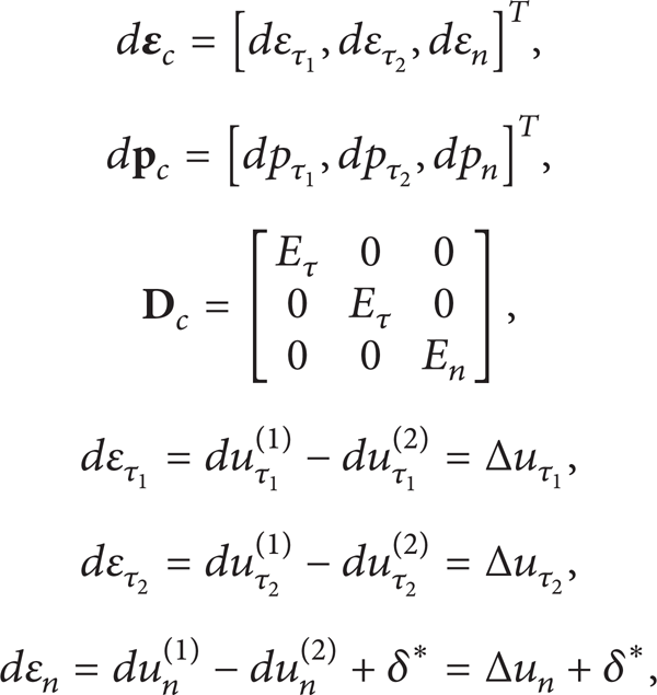
and δ* is the initial normal gap between contact surfaces.
In analogy with the expression of elastic-perfectly plastic constitutive model, slip function

where i = 1, 2,…, N f , c is a constant and the terms with “∼” are the variables describing contact. Therefore, the contact plastic (slip or separation) incremental displacement vector can be acquired by
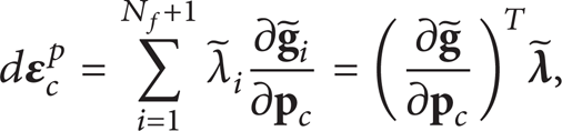
where

where

2.3. PQP Solution
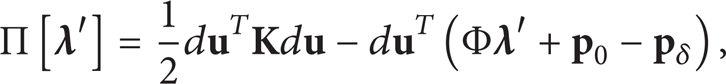
Among the admissible displacement fields, the actual solution minimizes the potential energy

controlled by (7) and (16), where

Posterior to introducing the interpolation shape function matrix
where
The control (7) and (16) can be derived as

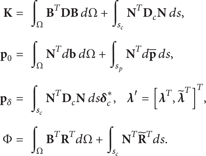
where

From (20) and (22), the following equations can be obtained:

where
It is necessary to eliminate the penalty factor E in the standard linear complementarity problem (25) to correct the solution. The matrices in (25) are in the forms of

After a series of derivations, (25) can be divided into

where

Apparently, the expressions in (28) duplicate the load vector and the stiffness matrix in substructuring which can thus be used to deal with contact problems, and the algorithm herein can be readily implemented in a code.
3. Details of the Computational Model
The compressor impeller, which comprises identical segments circumferentially, gives rise to a rotationally periodic structure. The impeller, with a shaft hole of diameter 34 mm, is mounted onto compressor shaft and sleeve via interference fit. The material of the sleeve and axle 7 is steel and that of the impeller is aluminum. Although adjacent blades are not largely gapped, impeller requires to be computed by using the three-dimensional model other than an axial symmetric one because of the cyclic symmetric structure that should be analyzed by substructuring. The global stiffness matrix is created merely by dividing meshes into one substructure mode. Besides, the computed results can be applied to other similarly constructed superelements, which thus significantly lower the computation cost. In other words, increasing repeated structures will augment the corresponding computational efficiency.
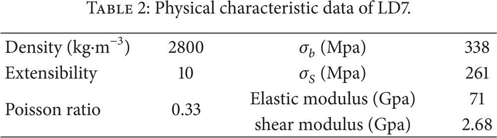
Table 1 summarizes the overall dimensions and the basic design data of the impeller, and the physical characteristics of LD7 are listed in Table 2.
Major dimensions of the impeller.

Physical characteristic data of LD7.
The substructure model is exhibited in Figure 3. The computational models of the impeller are shown in Figure 4.
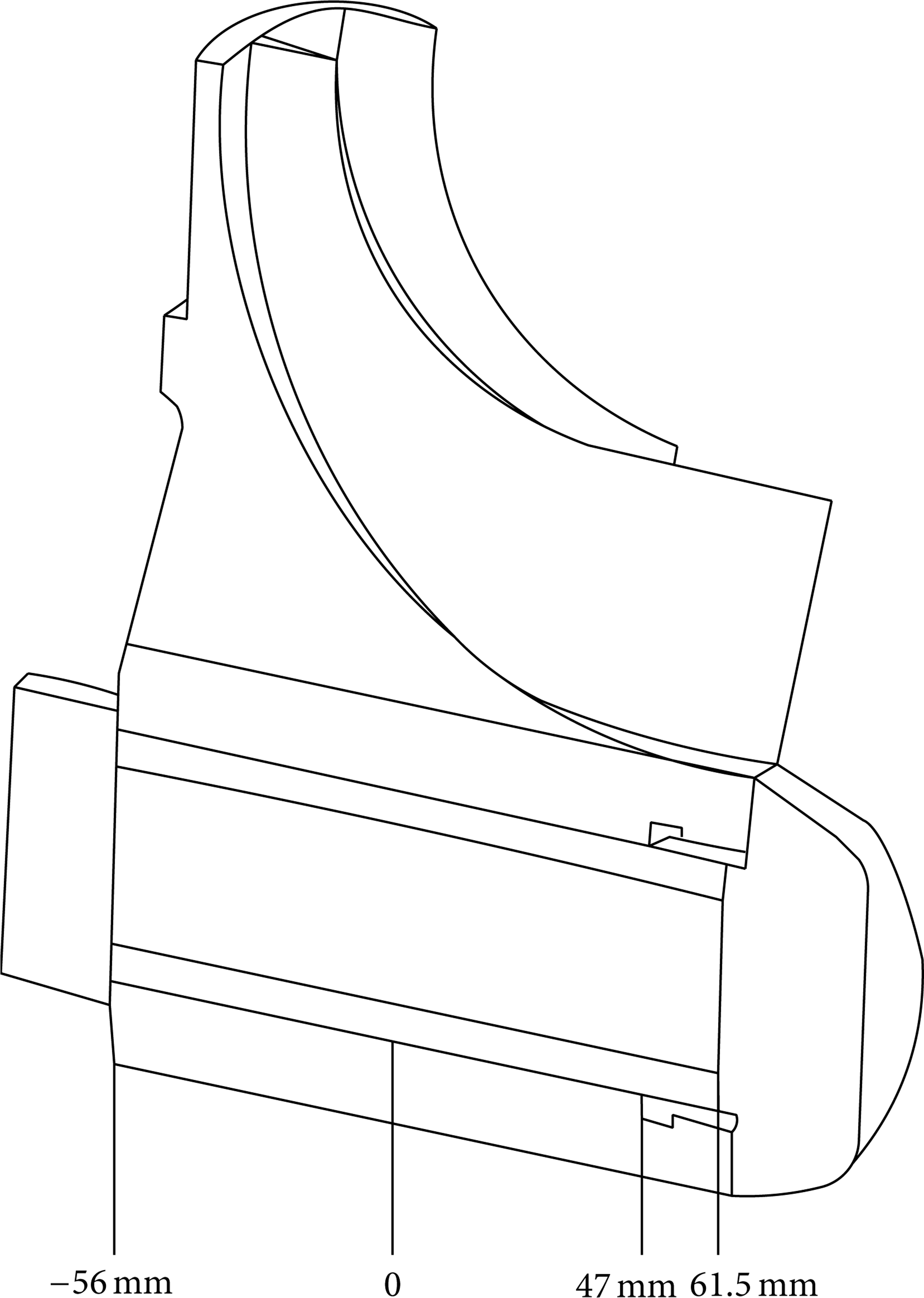
The model of substructure.

The whole computational model of impeller.
The computational model uses a four-node tetrahedron solid element with three degrees of freedom at each node to truly reflect the impeller. The influences of temperature and pressure loading are neglected because they are smaller than the centrifugal force due to high-speed rotation. Meanwhile, the centrifugal stiffening effect [18] is also considered. In the FE contact analysis, contact surfaces are defined to allow nodal sliding.
Simulating the tested constitutive curve reveals that the elastoplastic computation of the impeller follows a linear hardening model (Figure 5).

Stress-strain tested curve of LD7.
To evaluate the changes of displacements and stresses regarding the impeller, 60% of the full load is first applied according to the results of the elastic model with the maximum induced stress close to the proportional limit, after which the impeller undergoes 60, 10, 10, 10, and 10% of the full load, unloading, and then reloading at 25000 rpm.
The compressor essentially succumbs to centrifugal forces owing to the high-speed rotation in the midst of overspeed and operation. δ1 and δ2 are defined as the amount of interference between shaft sleeve and impeller as well as that between shaft and shaft sleeve, respectively. As to δ1 (0.03, 0.04, and 0.05 mm) and δ2 (0.04, 0.05, and 0.06 mm), the load cases for different wall thicknesses h (7, 6, 5, and 4 mm) and overspeed rpms w (30000, 31000, 32000, 33000, 34000, and 35000 rpm) are computed.
4. Results and Discussions
4.1. Influence of Overspeed
The solid curves in Figure 6 represent the distribution of contact stresses of the external surface of shaft sleeve (surface between shaft sleeve and impeller), whereas the dashed curves correspond to that of the internal surface (surface between shaft and shaft sleeve). Their distributions along the axial direction at five rotational speeds are also illustrated (δ1 = 0.03 mm, δ2 = 0.04 mm). The right edge of the shaft sleeve external surface is of higher contact stress than other regions because impeller and shaft sleeve do not keep contacting persistently. The impeller is suspended at x = 47.0 mm (Figure 3) without contacting with the shaft sleeve external surface, the root discontinuity geometry which generates a stress concentration. Encountering the same amount of interference, the contact stresses of contacting surface reduce with accelerating rotation because of the raised centrifugal forces. In addition, the contact stresses of the surface edge barely change, and those of internal and external surfaces change identically.

(a) Normal contact stress distributions of the external surface of the shaft sleeve along the axial direction under different overspeed rpms. (b) Normal contact stress distributions of the internal surface of the shaft sleeve along the axial direction under different overspeed rpms.
Half of the contact points between impeller and shaft sleeve are separated at the rotational speed of 30000 rpm (Figure 6).
The solid curves in Figure 7 represent the distribution of contact stresses of the shaft sleeve external surface. The normal displacements of contact point pairs between shaft sleeve and impeller increase along the axial direction with rising radial dimension of the impeller (Figure 7).
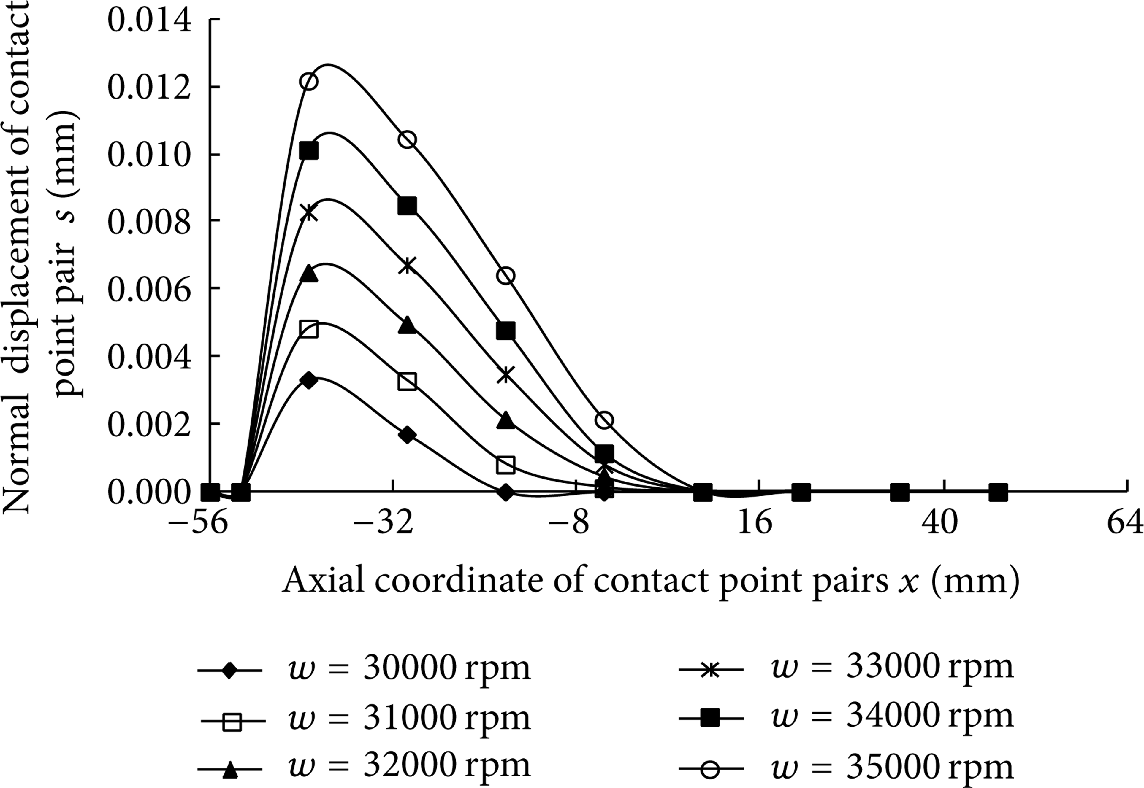
Variation of normal displacement under different overspeed rpms.
The normal displacement values for x = − 30.25∼ − 43.25 mm at the contact surface between shaft sleeve and impeller peak and thereafter decrease down to 0 along the axial direction. The contact stresses of contacting surfaces are inevitably nonuniformly distributed owing to the nonuniform distribution of normal displacements. We postulate that the nonuniform initial amount of interference manages to avoid displacement and unify contact stress. For instance, the amount of interference linearly rises (declines). Figure 7 also suggests that the normal displacement of contact point pairs is elevated with accelerating rotation.
4.2. Influence of Amount of Interference
The solid curves in Figure 8 correspond to the distribution of contact stresses of the shaft sleeve external surface, while the dashed ones represent that of the internal surface. The relationships between contact stresses and rotational speeds for various amounts of interference (case 1: δ1 = 0.03, δ2 = 0.04; case 2: δ1 = 0.04, δ2 = 0.05; case 3: δ1 = 0.05, δ2 = 0.06) are derived at the central contact point x = 21.25 mm. Figure 8 shows that the contact stresses of shaft sleeve external and internal surfaces linearly drop with accelerating rotation, and they also decrease with reducing amount of interference at the same rotational speed. The contact stress of internal surface which exceeds that of external one also decreases more rapidly, which can be attributed to the difference between materials (shaft sleeve and shaft: steel; impeller: aluminum) and the remarkably lower rigidity of aluminum than that of steel.
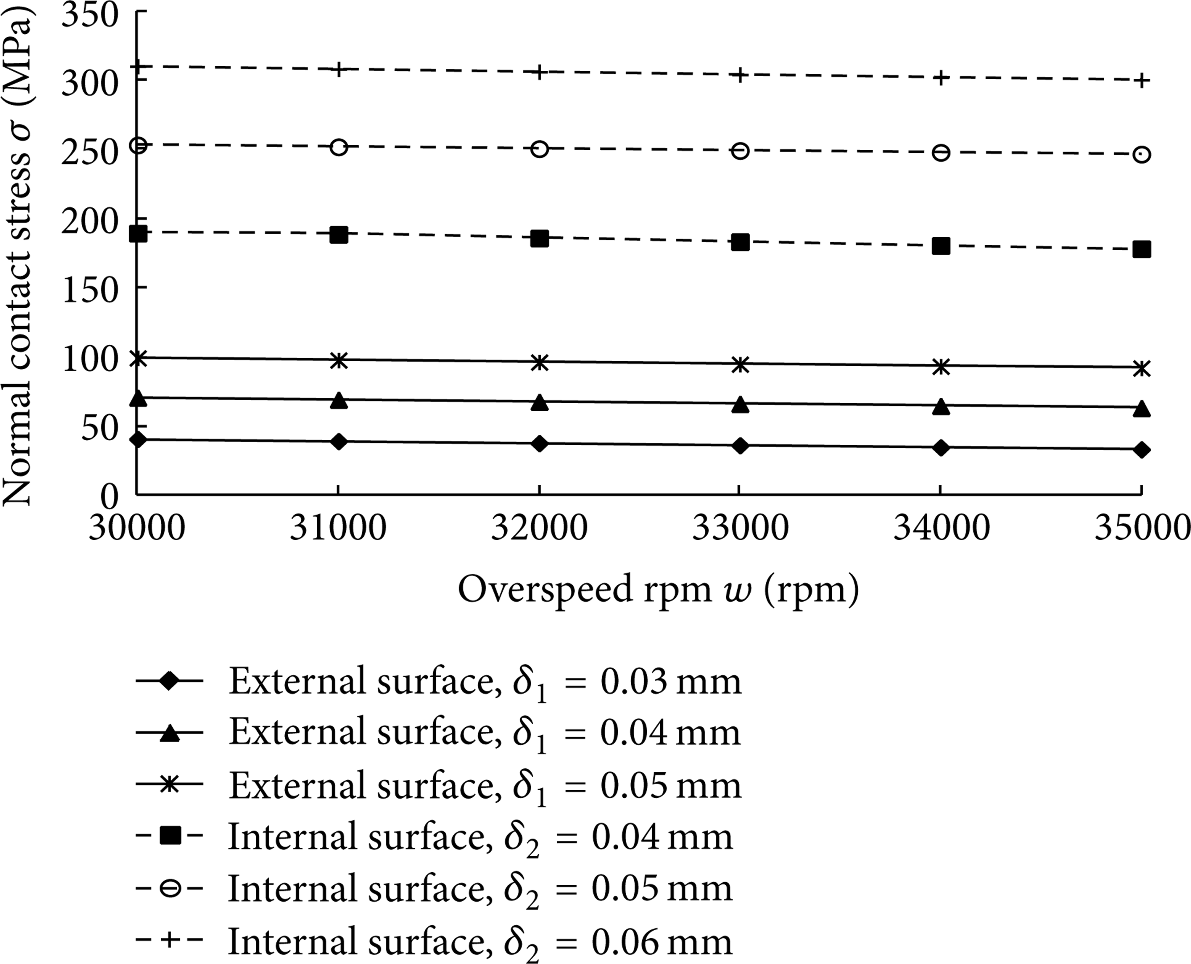
Variation of normal contact stress with overspeed rpm when the amount of interferences is different.
Consequently, the contact stresses of impeller, shaft, and shaft sleeve are essentially affected by the amount of interference between shaft sleeve and shaft which prevents the contact stress there between from fast decrease at high rotational speed, thereby guaranteeing the safety of overspeed prestressing.
4.3. Influence of the Wall Thickness of Shaft Sleeve
The solid curves in Figure 10 represent the distribution of contact stresses of the shaft sleeve external surface, while the dashed ones correspond to that of the internal surface. The relationships between contact stresses and rotational speeds for various wall thicknesses of shaft sleeve at the central contact point x = 21.25 mm are plotted in Figure 9. The contact stresses of both external and internal surfaces are lowered with accelerating rotation. With increasing wall thickness, however, the contact stress of internal surface increases, while that of external surface changes conversely at the same rotational speed. Thickening the wall of shaft sleeve that depends on the radius of external surface indicates increased impeller internal diameter and decreased impeller stiffness in case of constant amount of interference between shaft and shaft sleeve. Thus, the external surface is of lower contact stress, and we can ascribe the elevated contact stress of internal surface to the same reason.

Variation of normal contact stress with overspeed when the wall thicknesses of shaft sleeve are different.

Variation of maximum residual Von Mises stress of impeller under different overspeed rpms.
4.4. Maximum Residual Stress and Displacement
As to the impeller, Figures 10 and 11 exhibit the dependences of maximum residual Von Mises stress and displacement on overspeed rpm. The maximum residual Von Mises stress at 30000 rpm∼35000 rpm is located close to the internal hole rear of the compressor. The maximum residual radial displacement resides near the inner hole rear of the impeller, while the axial one is located adjacent to the disk edge. The maximum residual Von Mises stress and displacement both rise rapidly with accelerating rotation, which accords with the continuous expansion of plastic rear zone.
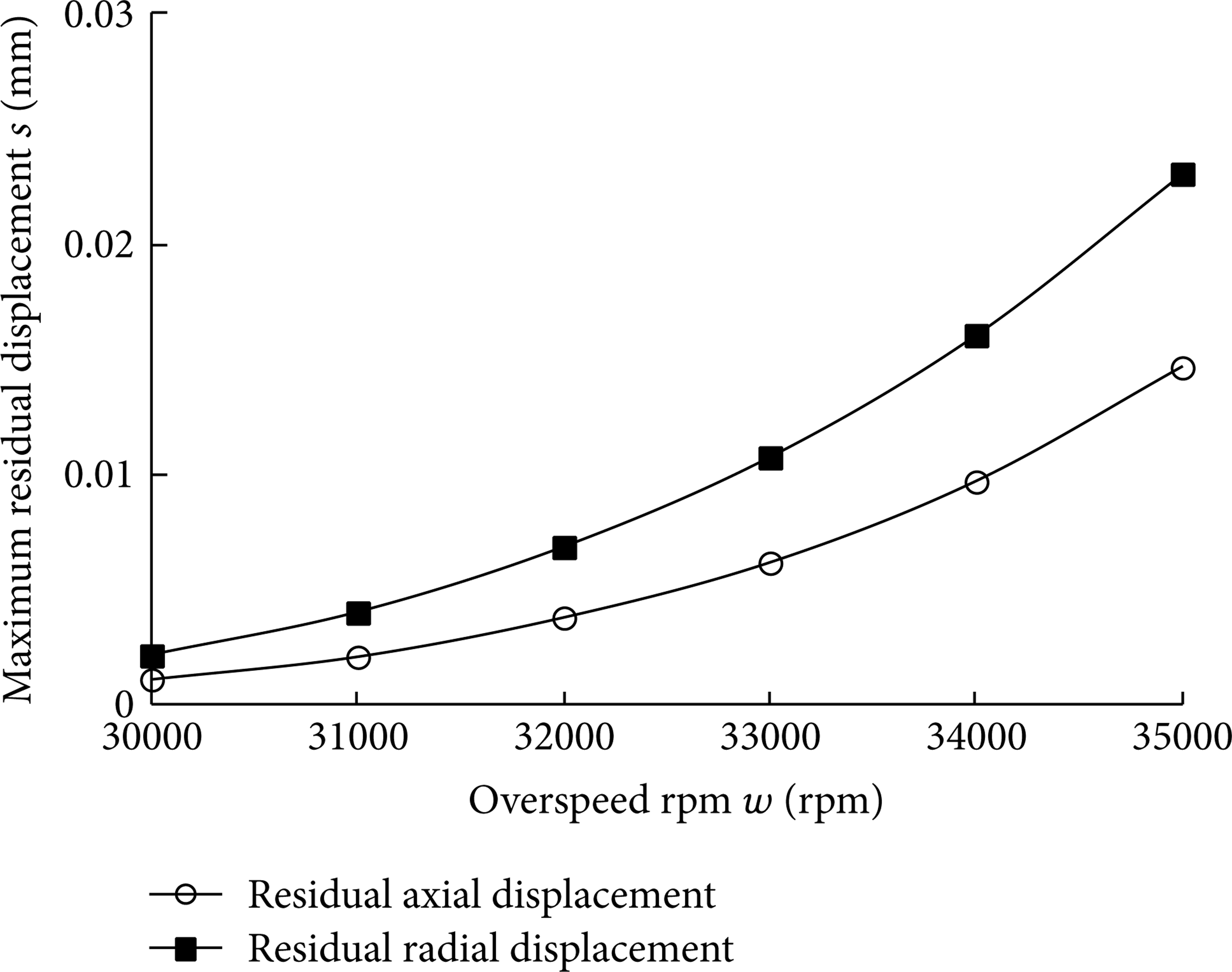
Variation of maximum residual displacement of impeller under different overspeed rpms.
4.5. Stress and Displacement under Working Conditions
Figure 12 presents the dependence of the maximum Von Mises stress of the impeller on overspeed rpm, in which the maximum Von Mises stress at working speed declines slowly with rising rotational speeds after overspeed prestressing, suggesting that the impact of prestressing on the impeller is weakened with accelerating rotation.
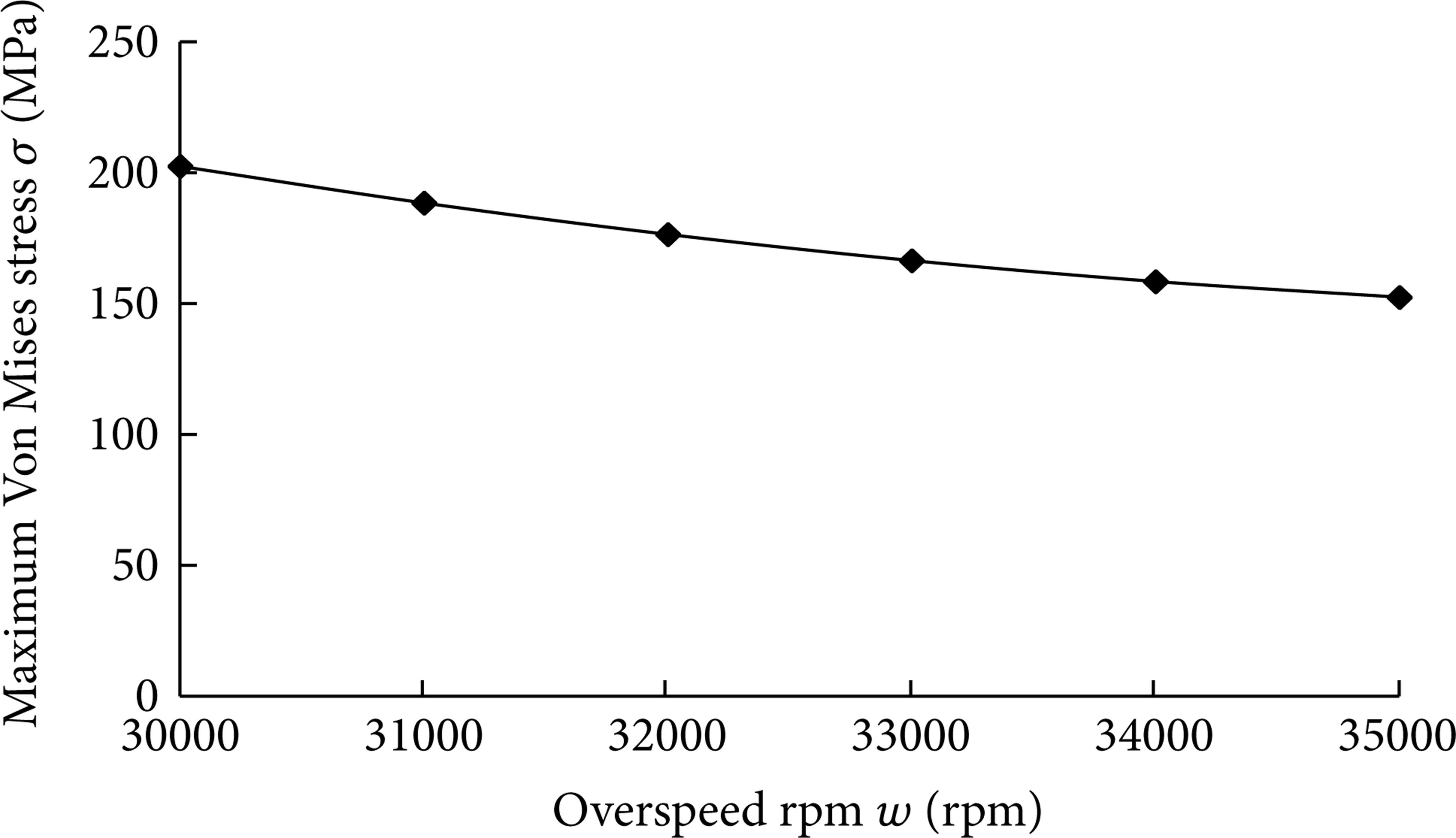
Variation of maximum Von Mises stress of impeller under different overspeed rpms.
Figure 13 exhibits the dependence of the maximum displacements of the impeller on overspeed rpm. The axial and radial displacements, which increase with elevating rotational speeds overall, first increase moderately at the speeds lower than 33000 rpm and then rapidly at those exceeding 33000 rpm.

Variation of maximum displacement of impeller under different overspeed rpms.
5. Conclusions
The PQP protocol manages to solve convergence problems and to reduce sophisticated high nonlinear problems (e.g., 3D elastoplastic problems) to standard linear complementarity ones by approximating the friction law via a polyhedral one.
At the overspeed of 30000 rpm, the contact region of the impeller radically sized higher is susceptible to displacement, and half of the contact points between shaft sleeve and impeller may be gapped. The computation results show that at different overspeed rpms, the impeller mass distributions and the normal relative displacements of the contact point pairs between shaft sleeve and impeller are apparently associated.
The contact stresses of shaft-shaft sleeve-impeller are mainly affected by the amount of interference between shaft and shaft sleeve. The contact stresses of the internal and external surfaces of shaft sleeve are linearly lowered with accelerating rotation, and the internal surface is of higher contact stress than the external one. To qualify the overspeed prestressing, it is critical to strictly control the amount of interference between shaft and shaft sleeve to prevent the contact stress from fast increasing. Meanwhile, the nonuniform initial amount of interference can get rid of displacement and unify contact stress.
The contact stress of the internal surface of shaft sleeve rises and that of the external surface reduces with thickening wall. The wall thickness should be minimized to maintain sufficient contact stress and to prevent it from fast changes along the axial direction.
The effects of prestressing minimizing the maximum impeller stress at working speed should be considered in identifying the optimal overspeed rpm. In the meantime, the impeller succumbs to tolerable residual deformation after reasonably costing overspeed. In this study, the impeller (calculation example) functions optimally at the overspeed rpms from 31000 rpm to 33000 rpm at which the maximum stress decreases to 167 Mpa, and the maximum displacement at working speed is rapidly augmented at over 33000 rpm.
Footnotes
Notation
Conflict of Interests
The authors declare that there is no conflict of interests regarding the publication of this paper.
Acknowledgments
This work is jointly supported by the Twelfth Five-Year Program of Connotation Construction Project for Shanghai Local Universities and Top Discipline Plan for Mechanical Engineering of Shanghai Municipal Education Commission.