
Abstract
This paper presents the finite element studies made on free vibration of isotropic and laminated composite cylindrical skew panels. A finite element analysis is performed using CQUAD4 and CQUAD8 elements of MSC/NASTRAN software. The effects of the panel angle, skew angle, aspect ratio, and length-to-thickness-ratio on fundamental natural frequency of vibration of isotropic cylindrical skew panels are studied. The effects of additional parameters such as fiber orientation angle, numbers of layers (keeping total thickness constant), and laminate stacking sequence on the fundamental frequency of vibration of antisymmetric composite laminates have also been studied. During validation and convergence study, it is found that the CQUAD8 element yields more accurate results than the CQUAD4 element. Hence the CQUAD8 element has been employed for the remaining part of the investigation. The fundamental frequency is found to increase with the panel angle and skew angle. The variation of the fundamental frequency with the number of layers is not appreciable when the number of layers is greater than about 6. It is also seen that the boundary conditions have significant influence on the fundamental frequency.
1. Introduction
The skew cylindrical panels find wide application in the aircraft and spaceship industry. Few analytical and numerical studies have been made on such panels. A great need exists for an elaborate study on free vibration of skew cylindrical panels and the present work is one attempt in this direction. Selmane and Lakis [1] have presented a method for the dynamic and static analysis of thin, elastic, anisotropic, and nonuniform open cylindrical shells. The open shells are assumed to be simply supported along their curved edges and to have arbitrary straight-edge boundary conditions. The method is a hybrid of finite element method and classical shell theories. Bardell et al. [2] have used the h-p version of the finite element method and made a detailed study of the vibration characteristics of completely free, open, and cylindrically curved isotropic shell panels. Singh [3] has presented the free vibration analysis of doubly curved open deep sandwich shells made of thin outer layers of high strength and high density material and a relatively thick core of low strength low density material. The Rayleigh-Ritz method is used to obtain the natural frequencies. Lee and Han [4] have discussed the free vibration analysis of isotropic plates and shells using a nine-node degenerated shell element. In this analysis first-order shear deformation theory has been used. Zhao et al. [5] have analyzed the vibration behavior of composite cylindrical panels by meshfree (meshless) approach. Hossain et al. [6] have presented an improved finite element model for the linear analysis of anisotropic and laminated doubly curved moderately thick composite shell panels. The model has been developed by considering first-order shear deformation theory. Liu et al. [7] have implemented the element free Galerkin method for static and free vibration analyses of general shell structures. The formulation has been verified through numerical examples of spatial shell structures. Civalek [8–11] has used the discrete singular convolution (DSC) method and performed free vibration analysis of laminated conical shells, rotating truncated conical shells and laminated composite conical and cylindrical shells. Malekzadeh et al. [12] have made three-dimensional free vibration analysis of arbitrary laminated circular cylindrical shells using a mixed layerwise theory and differential quadrature (DQ) method (LW-DQ). Kandasamy and Singh [13] have presented a numerical investigation of free vibration of skewed open cylindrical isotropic shells. First-order shear deformation and rotary inertia have been included in the formulation. Thin and moderately thick shells have been studied. Haldar [14] has used triangular shallow shell element for free vibration analysis of laminated composite skewed cylindrical shell panels. GulshanTaj and Chakrabarti [15] have studied the dynamic response of functionally graded skew shell using a C° finite element formulation. Numerical results are presented for cylindrical, spherical, and hyper shells for different boundary conditions and skew angles.
The present work deals with the finite element analysis of free vibration of isotropic and laminated composite cylindrical skew panels using CQUAD8 element of MSC/NASTRAN software. This element has 8 nodes with six degrees of freedom/node and is an isoparametric one. The finite element analysis can be used for all types of shell geometry, material model, loading, and boundary conditions. It leads to sufficiently reliable results when the effects of longitudinal and other inertias are included in the element formulation depending upon the problem on hand. With the availability of high speed computers with large memory, the number of elements in the finite element mesh should not be a constraint. The effects of skew angle, panel angle, fiber orientation angle, number of layers in the laminate for a given total thickness, laminate stacking sequence, and boundary conditions on the fundamental frequencies of cylindrical skew panels are investigated.
2. Validation and Convergence Studies
The geometry of the skew cylindrical panel with dimensions is shown in Figure 1. Figure 2 indicates cylindrical skew panel with global and local coordinate systems and u and v are the displacement components in x and y directions, respectively. Since u and v are inclined to the skew edges, the displacement boundary conditions cannot be applied directly. In order to overcome this, a local coordinate system (x′, y′) normal and tangential to the skew edges is specified and the required coordinate transformations are performed by the software.

Geometry of the skew cylindrical panel with dimensions.

Global and local coordinate systems for cylindrical skew panels used in finite element analysis.
2.1. Validation Check
The nondimensional fundamental frequency coefficient K
f
is defined as
Fundamental frequency coefficient (K f ) for isotropic cylindrical skew panels (α = 45°, Ø = 60°, L/R = 4.0).

In a similar manner a composite laminated cylindrical skew panel (antisymmetric graphite/epoxy angle-ply) with one curved edge fixed and all other edges free is analyzed and a validation check made. The material properties used are E l /E t = 40, G lt /E t = 0.5, and ν lt = 0.25. The values of K f obtained in the present work are compared with those available in the literature and the same are presented in Table 2. The K f values obtained are in good agreement with those available in the literature. From Tables 1 and 2 it can be seen that the CQUAD8 element yields more accurate result when compared with the CQUAD4 element. Hence CQUAD8 element is employed for further studies in the present work.
Fundamental frequency coefficients (K f ) for cylindrical skew composite panels (α = 45°, Ø = 60°, L/R = 4.0, t/R = 0.01).

2.2. Convergence Study
To arrive at the minimum number of elements to be used in the finite element mesh for reliable result, a convergence study has been undertaken. It has been performed on simply supported (S-S-S-S) (S3 boundary conditions) [16] and clamped (C-C-C-C) (C2 boundary conditions) [16] isotropic cylindrical skew panels having aspect ratio (= a/b) of 1.0, panel angle of 30°, and skew angles 0°, 15°, 30°, and 45° using CQUAD4 (four-node plate element) and CQUAD8 (eight-node isoparametric curved shell element) elements. The convergence details are presented in Table 3. A 40 × 40 finite element mesh is used in the further studies.
Convergence of fundamental frequency coefficient (K f ) for isotropic cylindrical skew panels (a/b = 1, a/t = 100, Ø = 30°).

3. Results and Discussion
The results of finite element analysis of cylindrical skew panels are presented in terms of nondimensional fundamental frequency coefficient K f for the following cases: (a) simply supported isotropic cylindrical skew panels, (b) clamped isotropic cylindrical skew panels, (c) simply supported antisymmetric angle-ply cylindrical skew panels, and (d) clamped antisymmetric angle-ply cylindrical skew panels.
3.1. Isotropic Cylindrical Skew Panels
Numerical studies have been made for a number of isotropic cylindrical skew panels with different aspect ratios, skew angles, and length-thickness ratios with simply supported and clamped boundary conditions. The results obtained are tabulated in Tables 4 and 5 for panel angles of 15° and 30°, respectively. The following conclusions are made:
K f increases as the skew angle α increases for constant values of a/b and a/t;
K f increases as a/t decreases for constant values of a/b ratio and skew angle α;
the panel angle and boundary conditions have considerable influence on K f value.
Free vibration of simply supported and clamped isotropic skew curved panels (Ø = 15°).

Free vibration of simply supported and clamped isotropic skew cylindrical panels (Ø = 30°).

3.2. Antisymmetric Angle-Ply Cylindrical Skew Panels
3.2.1. Simply Supported Boundary Condition
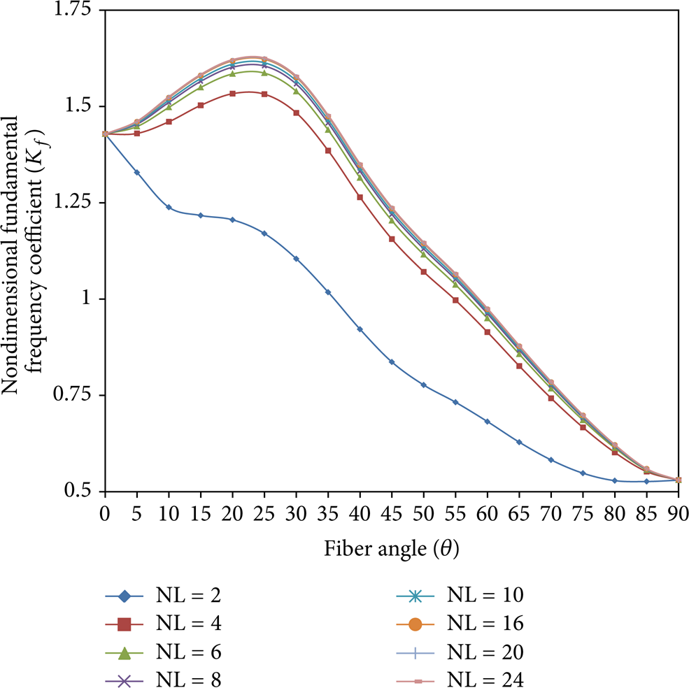
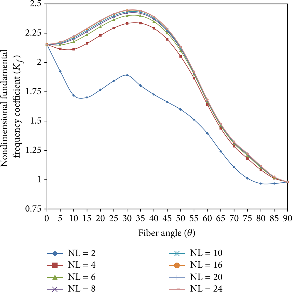
The variation of fundamental frequency coefficient (K f ) with skew angle (α), fiber orientation angle (θ), and number of layers (NL) for antisymmetric angle-ply cylindrical skew laminates under S3 boundary conditions [16] are presented in Figures 3, 4, 5, and 6 for panel angle = 15° and Figures 7, 8, 9, and 10 for panel angle = 30°, respectively. The increase in K f with an increase in NL beyond NL = 10 is not appreciable in all the cases. There is considerable difference in K f between NL = 2 and other values of NL. For NL > 6, K f attains a maximum value at a fibre orientation angle between 25° and 30° for skew angles up to 30°.

Values of K f for simply supported antisymmetric angle-ply cylindrical skew panels (α = 0°, Ø = 15°, S3, a/b = 1, graphite/epoxy).

Values of K f for simply supported antisymmetric angle-ply cylindrical skew panels (α = 15°, Ø = 15°, S3, a/b = 1, graphite/epoxy).

Values of K f for simply supported antisymmetric angle-ply cylindrical skew panels (α = 30°, Ø = 15°, S3, a/b = 1, graphite/epoxy).
Values of K f for simply supported antisymmetric angle-ply cylindrical skew panels (α = 45°, Ø = 15°, S3, a/b = 1, graphite/epoxy).
Values of K f for simply supported antisymmetric angle-ply cylindrical skew panels (α = 0°, Ø = 30°, S3, a/b = 1, graphite/epoxy).

Values of K f for simply supported antisymmetric angle-ply cylindrical skew panels (α = 15°, Ø = 30°, S3, a/b = 1, graphite/epoxy).
Values of K f for simply supported antisymmetric angle-ply cylindrical skew panels (α = 30°, Ø = 30°, S3, a/b = 1, graphite/epoxy).

Values of K f for simply supported antisymmetric angle-ply cylindrical skew panels (α = 45°, Ø = 30°, S3, a/b = 1, graphite/epoxy).
3.2.2. Clamped Boundary Condition
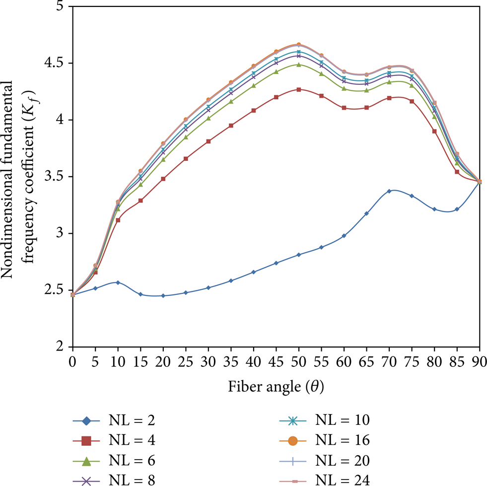
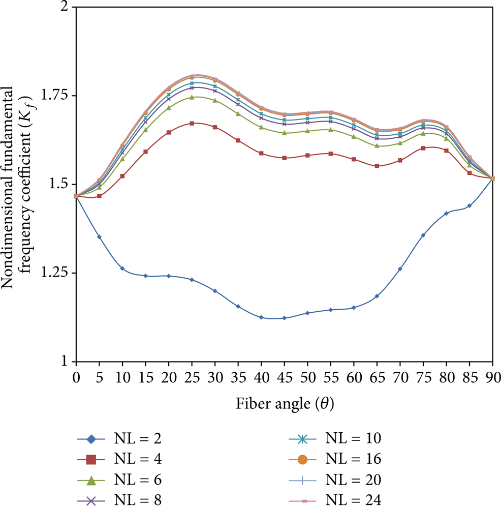
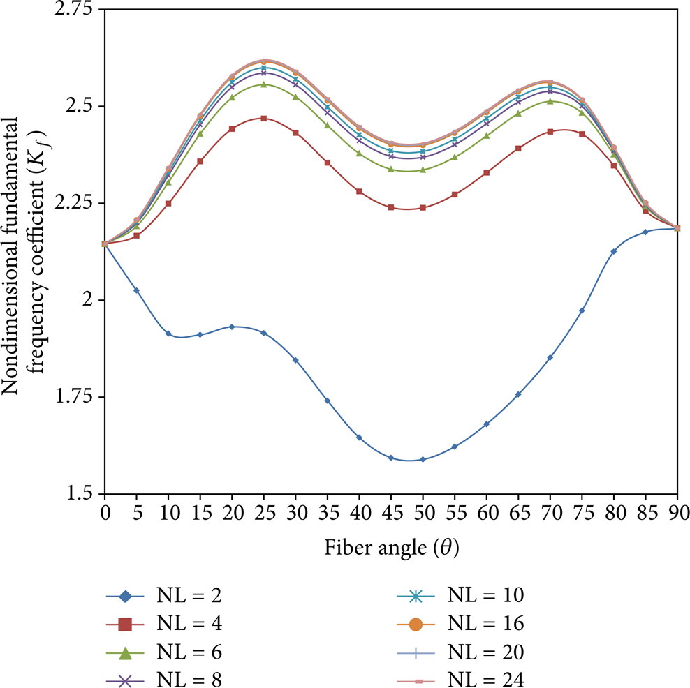
For antisymmetric angle-ply cylindrical skew panels with skew angles of α = 0°, 15°, 30°, and 45°, the variation of K f with θ and NL are presented in Figures 11, 12, 13, and 14 for panel angle = 15° and in Figures 15, 16,17, and 18 for panel angle = 30°. For NL = 2, K f initially decreases and varies later as shown in the relevant figures. The increase in K f with NL for NL > 10 is not appreciable. The boundary condition has a significant influence on the natural frequency, the clamped condition yielding higher value compared with the simply supported condition.

Values of K f for clamped antisymmetric angle-ply skew panels (α = 0°, Ø = 15°, C2, a/b = 1, graphite/epoxy).

Values of K f for clamped antisymmetric angle-ply skew panels (α = 15°, Ø = 15°, C2, a/b = 1, graphite/epoxy).

Values of K f for clamped antisymmetric angle-ply skew panels (α = 30°, Ø = 15°, C2, a/b = 1, graphite/epoxy).

Values of K f for clamped antisymmetric angle-ply skew panels (α = 45°, Ø = 15°, C2, a/b = 1, graphite/epoxy).
Values of K f for clamped antisymmetric angle-ply skew panels (α = 0°, Ø = 30°, C2, a/b = 1, graphite/epoxy).

Values of K f for clamped antisymmetric angle-ply skew panels (α = 15°, Ø = 30°, C2, a/b = 1, graphite/epoxy).
Values of K f for clamped antisymmetric angle-ply skew panels (α = 30°, Ø = 30°, C2, a/b = 1, graphite/epoxy).

Values of K f for clamped antisymmetric angle-ply skew panels (α = 45°, Ø = 30°, C2, a/b = 1, graphite/epoxy).
4. Conclusions
The following conclusions are made based on the above study of skew cylindrical panels with simply supported and clamped boundary conditions.
4.1. Isotropic Skew Cylindrical Panels
The aspect ratio, skew angle, panel angle, a/t ratio, and boundary conditions have a considerable bearing on the value of the first natural frequency of the panel. K f increases as the skew angle α increases for constant values of a/b and a/t. K f increases as a/t decreases for constant values of a/b ratio and skew angle.
4.2. Antisymmetric Skew Cylindrical Panels
The skew angle, panel angle, fiber orientation angle, number of layers, and boundary conditions have a bearing on the value of the first natural frequency of the panel. The increase in K f with an increase in NL beyond NL = 10 is not appreciable in all the cases. There is considerable difference in K f when NL = 2 and NL ≥ 4. K f is observed to attain a maximum value at a fibre orientation angle between 25° and 30° for skew angles up to 30° (simply supported boundary condition). The boundary condition has a significant influence on the natural frequency, the clamped condition yielding higher value when compared with the simply supported condition.
Footnotes
Symbols
Conflict of Interests
The authors declare that there is no conflict of interests regarding the publication of this paper.
Acknowledgments
The first author would like to thank the Management and Principal Dr. S. G. Hiremath of GM Institute of Technology, Davangere, Karnataka, India, for the kind encouragement and support provided. The second author would like to thank the Management of Jawaharlal Nehru College of Engineering, Shivamogga, Karnataka, India, for the kind encouragement and support provided. The third author would like to thank the Management, Principal Dr. N Ranaprathap Reddy, and Head of the Department of Civil Engineering Dr. Y. Ramalinga Reddy, Reva Institute of Technology and Management, Bangalore, Karnataka, India, for the kind encouragement and support provided.