
Abstract
This paper introduces a multiposture locomotor training device (MPLTD) with a closed-loop control scheme based on joint angle feedback, which is able to overcome various difficulties resulting from mechanical vibration and the weight of trainer to achieve higher accuracy trajectory. By introducing the force-field control scheme used in the closed-loop control, the device can obtain the active-constrained mode including the passive one. The MPLTD is mainly composed of three systems: posture adjusting and weight support system, lower limb exoskeleton system, and control system, of which the lower limb exoskeleton system mainly includes the indifferent equilibrium mechanism with two degrees of freedom (DOF) and the driving torque is calculated by the Lagrangian function. In addition, a series of experiments, the weight support and the trajectory accuracy experiment, demonstrate a good performance of mechanical structure and the closed-loop control.
1. Introduction
Hemiplegia is very common sequelae of brain damage such as stroke, and it affects greatly movements of lower limb [1]. Clinically, patients are usually treated with physical therapy provided by therapists, which has some disadvantages, such as inefficiency, intensive workloads, and vapidity [2]. Treadmill gait rehabilitation robotic devices have been developed for clinical training; for example, Lokomat robotic assistive device [3, 4] provides innovative possibilities for gait training in stroke rehabilitation while eliminating prolonged repetitive movements in a nonergonomic position on the part of the physical therapist. But these robotic assistive devices are not fit for patients in early stage of hemiplegia [5].
Locomotion training robots (LTRs) possess structures with smaller mass and liberate physicians’ workforce, as the actuator can be applied for motion transmission. There are two kinds of LTRs, namely, traction type and exoskeleton type LTRs [3]. The traction type LTRs are commonly used with fixed platform to which the users cannot move relatively. They are usually capable of high dynamic motion and easy to use, such as Erigo [6]. However these LTRs are single and boring for users and their effects improving life ability are not ideal. The exoskeleton type LTRs have found their applications in many occasions, such as the rehabilitation mechanism Rewalk [7], the space training NASA [8], and the military purposes BLEEX [9]. They can provide a variety of movements without space constraints, but they are expensive and tiring to wear [4, 5].
However, almost all locomotion training devices only have passive mode which provides tractive force to control users’ motion, and it is difficult to meet clinical demand. In this paper, compared with the conventional locomotion training robots, a novel robot system multiposture locomotor training device (MPLTD) is developed with posture-transform training and exoskeleton coordination training functions (Figure 1). Indifferent equilibrium mechanism is used to operate a 2-DOF manipulator driven for the locomotion training and a multiposture horizontal structure is used for weight support besides traditional suspended type. Two motion modes are demonstrated using a proportional integral and differential (PID) control system, which allows the motion modes to be realized in an integrated way [10–14]. Mainly, the active-constrained mode is achieved by closed-loop control and force-field control.
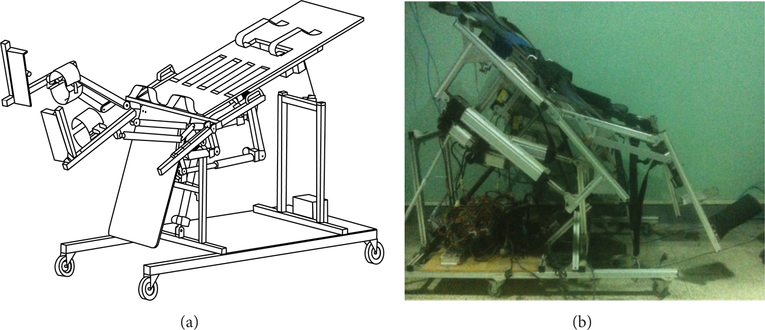
The multiposture locomotor training device.
In this paper with the use of position feedback of the driving motors, a semiclosed control scheme has been designed. However, this control scheme cannot achieve a complete closed-loop control. Du et al. [15] presented a fuzzy plus proportional-integral controller to achieve closed-loop control. We present intelligent algorithm to self-feedback closed-loop control scheme for the MPLTD. The basic principle of motion control in real time is to detect robot current position real time and give the next state instructions according to the current state.
This paper addresses force-field control to active-constrained mode for the MPLTD. Active-constrained mode control algorithm was based on the actual movement of the robot position
2. Design of the MPLTD
The MPLTD consists of three systems: posture adjusting and weight support system, lower limb exoskeleton system, and control system.
Security is done early in the design considerations: (1) mechanical structure limit is designed at the joints of the exoskeleton system to limit the rotation range and prevent reverse rotation. (2) Security algorithm is set up in the control system and when the sensors detect the location and speed of the exoskeleton in excess of the scope of protection, the drive will interrupt. (3) The abrupt stop buttons are set in multiple places, and experimenters or subjects can cut off the power supply in time.
2.1. Posture Adjusting and Weight Support System
2.1.1. Design Objective
It is convenient for users to transfer from hospital bed or wheelchair to the platform, and the angle range of the platform is 0°–80° according to specific requirements [12]. Considering safety and dynamic characteristics of users, the platform should have enough stiffness and be effective for users (mainly adults) with weight support (the maximum is 120 kg).
The bed frame structure of the device has three degrees of freedom, including trunk fixed part, adjustment part, and lower limbs auxiliary part (Figure 2). The function of the trunk fixed part is mainly user positioning and weight support, providing the angular variation from 0° to 80°. Adjustment part is a passive slide degree of freedom without tractive force and can adjust position according to users’ different body sizes. The main function of lower limbs auxiliary part is to facilitate users’ wearing lower limb exoskeleton and when training starts, support plate is folded up by putter 2, to prevent movement interference.

The posture adjusting and weight support system.
Fixed belt is installed on the sliding plate of the adjustment part, to fix users on the sliding plant which can slide along the axial Y direction, to adapt to different users’ trunk sizes; at the same time the distance of axial X is adjustable, to adapt to different breadth of users. Weight support is combined with two methods: the bed frame structure itself can support part weight of users, and the suspension mode under crotches and underarms also is able to support part. Adjusting the tensile force of suspension bandage can change the percentage of weight support. There are inflatable airbags outside the bandage to relieve the oppression of bandage to users’ blood vessel and nerve. The purpose of these methods is to prevent sports injuries and fatigue and not to affect the lower limb rehabilitation training exercise.
2.2. Lower Limb Exoskeleton System
2.2.1. Objective
Lower leg exoskeleton length (from knee joint to pelma) is adjustable and the range is 390–570 mm, while upper leg exoskeleton length (from hip to knee) is also adjustable and the range was 325–505 mm [16]. The angle of greatest flexion of hip joint (angle between thigh longitudinal axis and neutral position) is 10°–40°, while the knee joint largest range (angle between calf longitudinal axis and thigh longitudinal axis) is 0°–70°, and the dorsiflexion and plantar flexion of ankle joint is in the normal range—15°–20° [17].
The lower limb exoskeleton system consists of indifferent equilibrium mechanism, linear motors, bandage, and pedal with gasbag. Inheriting the biological structure of human legs, the main structure of the indifferent equilibrium mechanism is designed based on serial-restraining and parallel-driving principle with two degrees of freedom (Figure 3), whose structure size meets H/h = L/l. When the angle between the linear guideway and the bed frame is small, the direction of the combined strength of the mechanism's and legs’ weight is perpendicular to the linear guideway, so it almost does not need tractive force to make it move, which is the principle of indifferent equilibrium. This mechanism is very suitable for users under active-constrained mode, because users do not have to overcome the gravity of their own lower limb to achieve locomotion training. Linear actuator 2 drives hip joint and actuator 1 drives knee joint, interworking to simulate the gait for users’ passive locomotion training.

The lower limb exoskeleton schematic diagram.
The footboard can slide along rigid rod L, to adapt to different users’ lower limb length. There are two groups of gasbag devices, respectively, on the place of tiptoe and heel, and the charging and discharging process is implemented by control system, changing plantar pressure to simulate the plantar flexion and dorsiflexion close to actual gait.
3. Kinematics Analysis of MPLTD
3.1. Kinematics Analysis
In order to realize the simulation of the locomotion training, a kinematic model is built and the schematic diagram is shown in Figure 4, of which, A and B are the travels of linear actuators 2 and 1, respectively; C, D, E, and F are the length of rigid rods; ΔA is the angular variation between h2 and E2 in the pentagon AD2E2h2C2, and ΔB is the angular variation between E and F in the pentagon BDEFC, and Δ3 = ΔA − ΔB.

Thekinematic model of the indifferent equilibrium mechanism.
The angular variation of hip and knee in normal gait as known conditions; according to the geometric relationship in Figure 5, the travels of linear actuators 2 and 1, respectively, are calculated by inverse kinematics solution.

Angular variation of normal gait and the inverse kinetics solution results.
The results are as follows:

of which Δ1 and Δ2 are the angular variation regulation of hip and knee, respectively, in normal gait as in Figure 5(a), and the travels of linear actuators 2 and 1 are described as in Figure 5(b).
3.2. Dynamics Modeling
Lower extremity is simplified into an open two-link model and an appropriate coordinate system is established in this paper as follows (Figure 6).
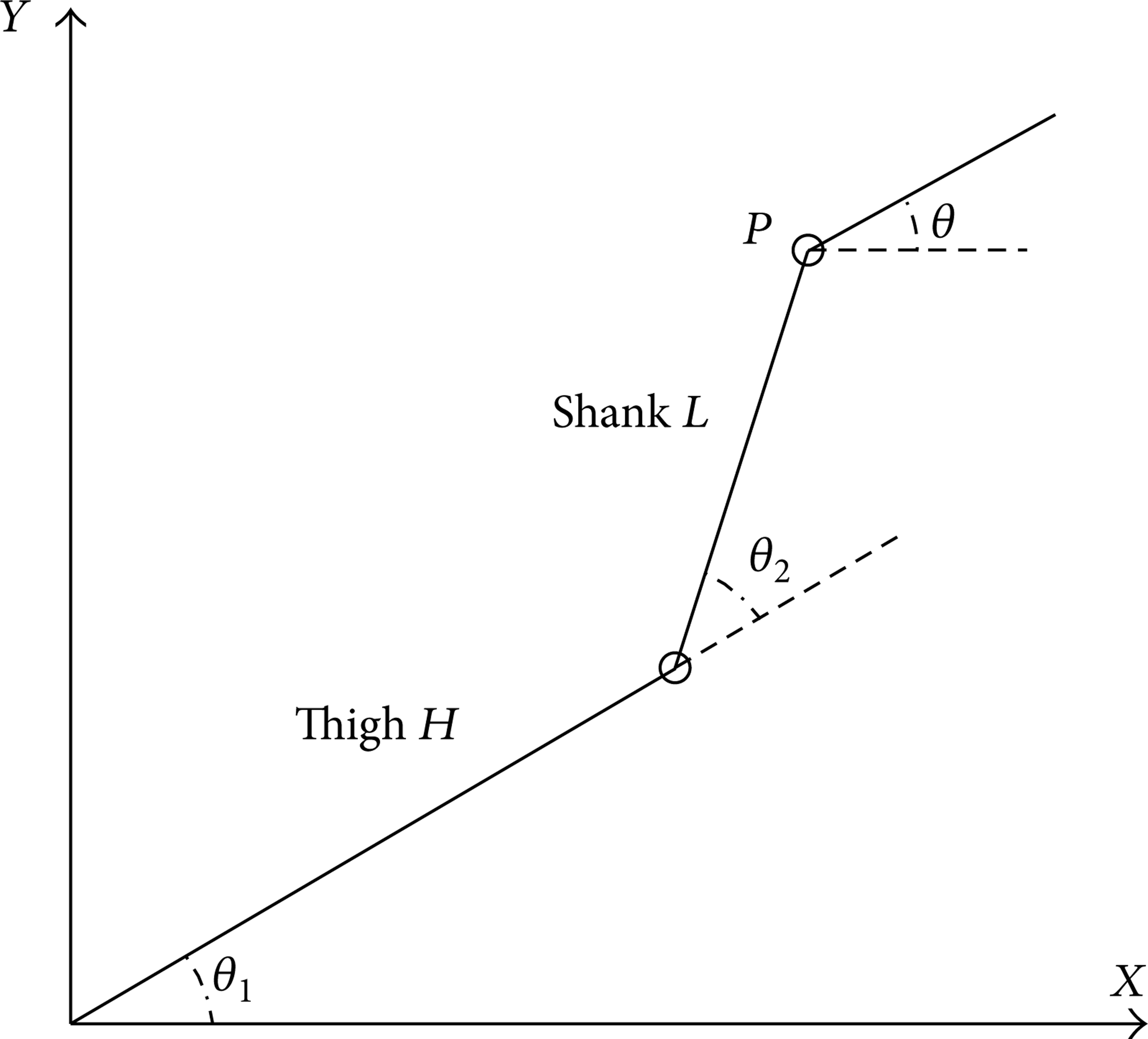
The dynamical model of lower limb exoskeleton.
Lower limbs terminal position coordinates are as follows:

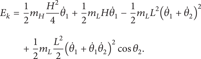
Kinetic energy of lower limb is as follows:
Potential energy of lower limb is as follows:

Lagrangian function is as follows:

By Lagrange equation,

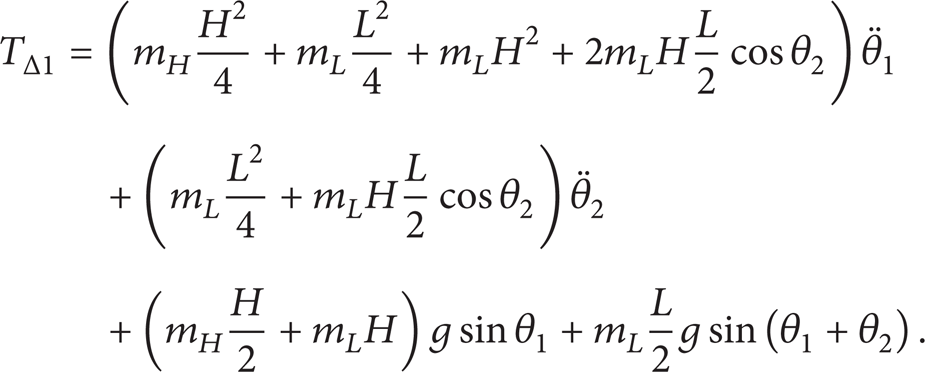
Due to low velocity of lower lime, the joint torque caused by the Coriolis force and centrifugal force is ignored, while the inertia force and gravity moment remain. The torque driving hip is as follows:
Similarly, the torque driving knee is as follows:

The Jacobian matrix equivalent to the hip and knee joints to maintain the applied force of foot force field is

Equivalent torque is as follows:

By the conditions of the generalized force,

The force matrix of two linear actuators is calculated and prepared for the control system. Physical significance of all symbols in equations refers to Table 1.
Physical significance of all symbols in equations.

4. Control System Design
In order to obtain the control algorithm using real-time feedback of joints and velocity control of the driven motors, a control system is developed, which includes industrial computer, controller, and sensors [18]. Without feedback controllers design, the open-loop control mode of MPLTD based on the inverse kinematic modeling will have limited control accuracy due to external influences. Owing to the angle sensors, closed-loop control scheme for MPLTD based on feedback is meaningful so that the motion control accuracy can be significantly improved. The passive mode and active-constrained mode are achieved by position, velocity, and current control. In the passive mode, the control model of the MPLTD relates the joint angle velocities to the time derivative of gait simulation. The target of the control is for the joint angles measured by the encoders installed in the motor tails to approach their desired values, while, in the active-constrained mode, torques of these two motors are controlled by current control, which is achieved according to the linear relationship between thrust and electric current within the operating range, and detailed interpretation will be mentioned later (Figure 9).
4.1. Passive Mode
The basic motion control principle of MPLTD in real time is to detect its current position real time and send instructions to next state according to the current state. MPLTD adoptive Panasonic servo motor drive control system is three-loop control system [19], the innermost layer is the current loop, and from the inside to the outside are the speed loop and position loop.
Under passive mode, lower limbs of the user are completely in passive traction state. The movement carries out the parameters set in advance, while abnormal movement patterns are completely inhibited [20]. In the passive control process, the torque output of the motor can achieve the maximum value which is adjustable by drive. The industrial computer sends commands to the controller in the form of pulses, and then the controller calculates the corresponding position and velocity. The linear actuators of hip and knee joints cooperate to complete movement according to predetermined speeds.
4.2. Active-Constrained Mode
Active-constrained mode control algorithm is to determine the force

Force-field controlling diagram.
Control algorithm instruction.
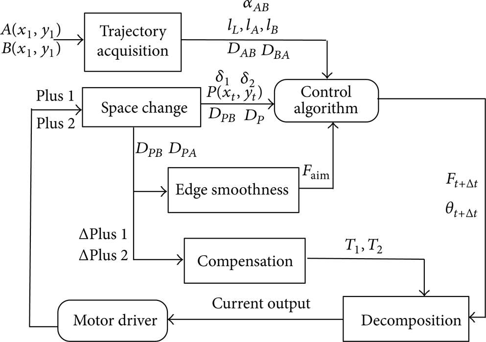
Active-constrained mode algorithm process structure.
In the active-constrained mode, if exoskeleton ends run within a set trajectory range, users can drive the lower extremity exoskeleton to do movement in the state of freedom; while exoskeleton ends deviate from the target trajectory, the constraint force field will pull limbs to the target trajectory from the wrong position by the most direct route. Due to users’ weak control to muscles and joints, the variation of the constraint force should be soft and gentle. The degree of constraint force can be adjusted according to the actual physical conditions of users during training process, to achieve different training difficulty.
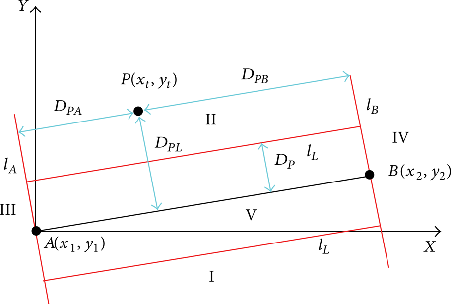
Taking the control algorithm of straight trajectory in the active-constrained mode as an example, AB is the desired straight trajectory, A(x1, y1) is the starting point, and B(x2, y2) is the end point. The normal force of AB at the end point of the exoskeleton restrains the end point on the desired trajectory; and the tangential force provides auxiliary power or resistance from A to B, to achieve weight loss or gain.
The coordinate system is shown in Figure 8 A(x1, y1) = (0, 0). The auxiliary lines l L , l A , and l B divide the motion space into five subregions I, II, III, IV, and V, of which l A and l B are lines passing through points A and B, respectively, and perpendicular to the line AB, l L is line segment whose distance is D P to line AB, and D P is the prescribed maximum error beyond the trajectory line AB. P(x t , y t ) is the actual location of the end point of the exoskeleton. D PA , D PB , and D PL are the distances from point P to lines l L , l A , and l B , respectively, by which the subregion where P is can be recognized.
When P enters the subregion III, still close to the point A (
When P enters the subregion I (D
PL
≥ 0 and
When P enters the subregion V, within the range of error band (
4.3. Electrical Control Circuit of Plantar Gasbag
Electrical control circuit design is shown in Figure 10. In order to ensure easy and reliable control, circuit design and the connection adopt the simplest way, as shown below. Controller communicates with the driver through Encoder CHA-CHZ pin of the Controller and the pin OA-OC of the driver to collect the encoder output signal; controller communicates with the driver through Drive STEP and DIR pin of the Controller and PLUS and SIGN of the driver to send digital pulse signal to the driver; controller communicates with the driver through Drive A pin of the Controller and Drive A pin to transmit analog signals to driver; controller communicates with the driver through ENA pin of the controller and SRV-ON pin of the driver to control the motor.

The corresponding channel of controller to driver.
5. Experiment Results
To demonstrate the performance of the multiposture locomotion training device, we have implemented three series of experiments: the weight support experiment, the repeatability and stability experiment of passive mode, and the accuracy experiment of active-constrained mode.
Ten healthy subjects are recruited to participate in these three series of experiments. All subjects have no history of serious diseases (6 men and 4 women; mean age: 24.5 years, range: 22–28, height: 175 ± 7 cm, and weight: 70 ± 10 kg). All subjects participate with informed consent and the approval of the local ethics committee. None of the subjects do exercise vigorously before the experiment and participated in similar experiments previously (Figure 11).

One subject's experimental process.
5.1. Weight Support Experiment
Ten healthy subjects participate in the weight support experiment, and they wear the monitoring system “Mindray PM-8000 Express” to ensure their body comfort in the process of experiment, which can detect rhythm of the heart, blood pressure, and other physiological parameters in real time. Plantar pressure distribution measurement system “Novel pedar-x” is adopted to measure plantar pressure, which can record the whole pressure value, pressure distribution, and peak pressure value, and the measuring range is 30–1200 kPa and resolution is 5 pa. Plantar pressure transducers show that the average of 10 subjects’ maximum pressure is 122.5 ± 21.4 kPa with traditional support method, while the value drops to 91.3 ± 18.6 kPa with the combined method as shown in Figure 12, supported by the bed frame structure and suspension bandage with inflatable airbags under crotches and underarms. The average of 10 subjects’ maximum pressure decreases to 31.2 kPa, and the reduction ratio is 25.5%. Reduction of the maximum pressure suggests that pressure distribution is more uniform and the subjects’ subjective feeling is more comfortable.

The weight support experiment for testing pressure of users’ weight support.
5.2. The Repeatability and Stability Experiment of Passive Mode
The purpose of the experiment is to test the repeatability and stability of passive mode, to help users establish the scope and sequence of hip and knee joints under the normal gait. In this experiment, step frequency is 0.2 Hz, and the angular transducers fixed outside of the hip and knee joints of the exoskeleton collect angles changing with time in 3 cycles as shown in Figure 13.
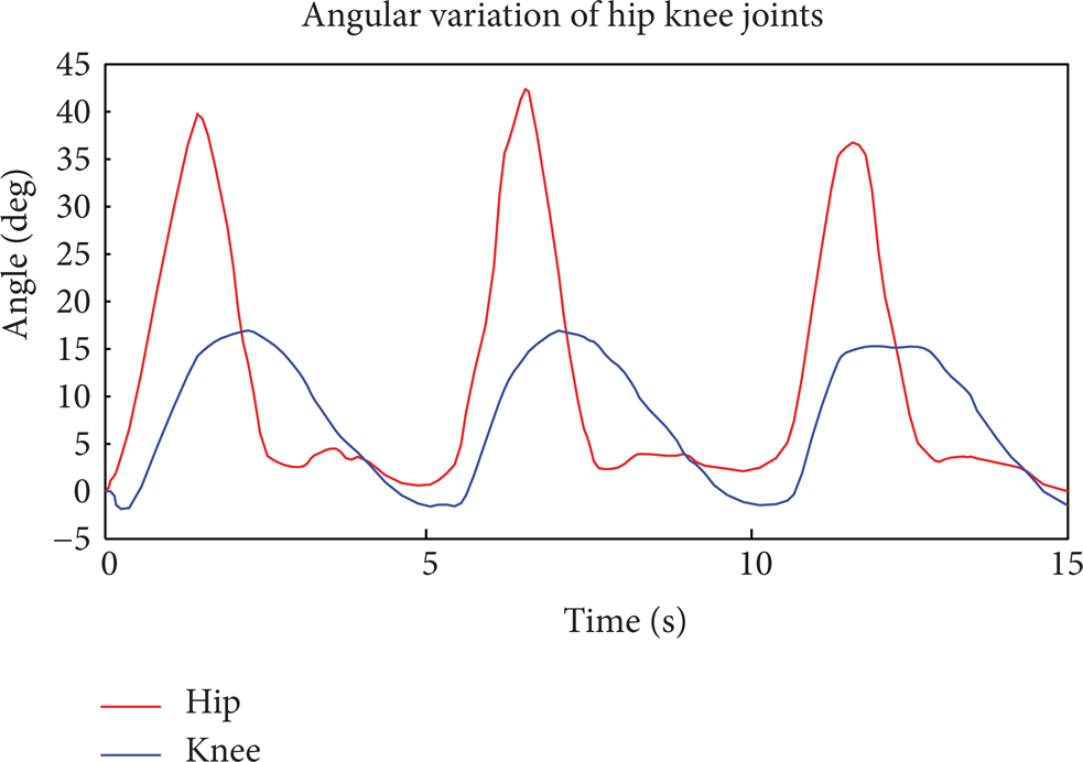
Angular variations of hip and knee joints.
The motion parameters are accurate with a good reproducibility, because of the strong enough constraint force which is provided to lower limb by the exoskeleton in the passive mode. We calculate the maximum relative errors of hip and knee movement angles of the 10 subjects in the passive mode in 100 cycles, and the results show that the relative error of the knee joint is slightly higher than the hip, but all are less than 6% as shown in Figure 14.

The results of the repeatability and stability experiment of passive mode.
5.3. The Accuracy Experiment of Active-Constrained Mode
Subjects do reciprocate linear motion without restraint; when the track is within the error range, the exoskeleton follows up; when the track is out of the error range, the exoskeleton provides constraint force to the reconnected lower limb within the error range. The experiment is to prove the accuracy of the control method which subjects participate in under the active-constrained mode.
Angles of hip and knee joints are collected in the same way as passive to calculate positions of the end of the exoskeleton by kinematics positive solution as the following equation:
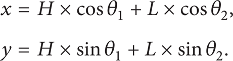
The trajectories composed of these positions are drawn out in the sagittal plane when the platform is in different angles 0°, 45°, and 60° in Figure 15. The results show that all the trajectories are within the error range in 100 cycles (block representing the error range in Figure 15).

The results of the accuracy experiment of active-constrained mode.
6. Conclusions
This paper provides the closed-loop control to accuracy control for the MPLTD. By introducing a force-field control, a new active-constrained mode is proposed for the indifferent equilibrium mechanism. The novel active-constrained mode is constructed by the matrix between trajectory and force field. A series of trajectory accuracy experiments in various angles demonstrate a satisfactory performance of the active-constrained mode. Considering the fatigue and aging of the indifferent equilibrium mechanism, we will focus on robust adaptive control for the MPLTD in the future work.
7. Discussion
Robot-assisted therapy has been proved effective for dyskinesia and has many unique advantages compared with traditional treatment, such as repeatability, accuracy, and objectivity. But some studies have shown that the effect of robot-assisted rehabilitation for improving patients’ activities of daily life (ADLs) is limited. The next step is putting MPLTD into the use of clinical trials to inspect its effect.
Vibration stimulation combined with multiposture upper-extremity training device has been proved as a kind of efficient auxiliary means to improve the efficiency of neurological rehabilitation in our previous study. We have tried to apply this pattern to MPLTD. Through experiments, effect of lower-extremity rehabilitation is worth to continue to study, but comparison experiments have not been done. Further experiments need to be studied to prove the effectiveness of this pattern in neurological rehabilitation process of lower limb, and several different methods of feedback (e.g., auditory feedback) should be compared to apply to auxiliary method of rehabilitation engineering.
Conflict of Interests
The authors declare that there is no conflict of interests regarding the publication of this paper.
Footnotes
Acknowledgments
The study is supported by grants from National Key Technology R&D Program of China (Grant no. 2009BAI71B00).