
Abstract
Underwater wireless sensor network (UWSN) features many unique characteristics, including slow propagation speed, high end-to-end delay, low available bandwidth, variable link quality, and energy constraint. All these problems pose a big challenge to devise a transmission efficient, energy-saving, and low delay routing protocol for UWSNs. In this paper we devise a relative distance based forwarding (RDBF) routing protocol, which aims to provide transmission efficient, energy-saving, and low delay routing. We utilize a fitness factor to measure and judge the degree of appropriateness for a node to forward the packets. Under the limitations of the fitness factor, RDBF can confine the scope of the candidate forwarders and find the beneficial relays to forward packets. In this way, only a small fraction of nodes are involved in forwarding process, which can distinctly reduce the energy consumption. Moreover, using only the selected beneficial nodes as forwarders can both enhance the transmission efficiency and reduce the end-to-end delay. This is because the distances of these nodes to the sink are the shortest and the hop counts of routing paths consisted by these nodes are minimum. We use the ns-2 based simulator to conduct our experiment; the results show that RDBF performs better in terms of packet delivery ratio, end-to-end delay, and energy efficiency.
1. Introduction
On the earth, 71% of the surface is covered with oceans; this immense area contains abundant resources and various creatures. But compared with the terrestrial environment we know just very few about the ocean environment. As more and more people turn their focus to the oceans, there has been growing interest in researches of this field. However, the oceans environment is so unpredictable and dangerous that most of the underwater areas are where people cannot reach personally. People spontaneously think of the sensor networks which have been extensively used in terrestrial environment. The sensor networks have been rapidly applied in oceans, which are exactly the underwater wireless sensor networks (UWSNs).
In recent years, UWSNs have been playing key roles in many applications related to aquatic environment, such as ocean monitoring, offshore oil/gas exploration, seismic monitoring, and marine military defense. In fact, with many inherent features, UWSNs are significantly different from the terrestrial sensor networks. The main one is that the UWSNs have to utilize acoustic signal as the transmission media, because the radio wave performs poorly in underwater. This difference results in that the UWSNs have to be redesigned in many aspects. The speed of the acoustic signal is five orders of magnitude slower than the radio wave and varies with the underwater scenarios, which makes some routing algorithms such as those based on time of arrival less efficacious. At the same time, the topology of the UWSNs is variable because the sensor nodes drift with the ocean current in any direction. Together with other problems existing in UWSNs, all of these make it a challenge [1, 2] when we try to design a transmission efficient, energy-saving, and low delay underwater routing protocol.
For all this, many routing protocols [3] for UWSNs have been proposed in recent years. These protocols can be sorted according to different emphases. When considering the communication path, these protocols can be divided into communication path based and non-communication-path based protocols.
The former protocols [4–6] relay on the communication paths established ahead of time. When a source sensor has packets to send, it just transmits the packets to its next hop nodes along the communication paths associated with this source node. And the next hop nodes will forward these packets to their next hop nodes. In this way, the packets can finally reach the destination node. The chie task of this sort of protocols is establishing the communication paths, which is a time-consuming and complicated process. In addition, the mobility of the sensor nodes can disorganize the topology of the established paths dramatically. Rebuilding the communication paths will cost extra energy and time, which will degrade the performance of the routing protocols.
The latter sort of protocols is non-communication-path based. When the sender nodes have packets to send, there is no established path for them. They need to find the appropriate next hop nodes immediately according to the routing schemes. In this kind of protocols, it need not cost any energy and time to establish and maintain the communication paths. While the key point of these protocols is how to find the most appropriate next hop nodes; a packet can be sent to a single next hop node or multiple next hop nodes. Many routing protocols [7–10] utilize the broadcast technology and introduce some parameters to control the number of the next hop nodes. But the bounds used in these protocols are neither flexible nor accurate enough to select the most appropriate next hop nodes.
In this paper, we propose a relative distance based forwarding protocol (RDBF) to overcome these challenges. The distance to the sink [11] node is an absolute parameter to decide the appropriateness of the node to be the next hop node. We use a fitness factor which reflects the appropriateness and priorities of a sender's neighbor nodes to relay the packets for it. RDBF utilizes the fitness factor to limit the scope of the candidate forwarders and find the beneficial relays to forward packets. Within the limitations of the fitness factor, only a small fraction of nodes are involved in forwarding process, which can distinctly reduce the total energy consumption. Moreover, using only the selected beneficial nodes as forwarders can both enhance the transmission efficiency and reduce the end-to-end delay. This is because the distances of these nodes to the sink are the shortest and the hop counts of routing paths consisted by these beneficial nodes are minimum.
The rest of this paper is organized as follows. In Section 2, we introduce several proposed routing protocols for UWSNs and indicate their problems. In Section 3, we describe our new routing protocol (RDBF) in detail. In Section 4, RDBF is evaluated through an ns-2 based simulator and we analyze the results in some different ways.
2. Related Works
Recently, some routing protocols for UWSNs have been proposed. Among these protocols, some are based on the established communication paths, and others are not. In fact, most of the non-communication-path based protocols are also location based.
In [4], a communication path based routing protocol (H2-DAB) was proposed. The sensor nodes must form layers from the surface to the bottom. And H2-DAB completes its task in two phases. In the first phase, sink assigns each floating node a dynamic HopID by broadcasting a Hello packet. Every node received this Hello packet updates and rebroadcasts it. In the end, each node in the network can get a HopID which corresponds to the layer it belongs to. The node in a deeper layer will get a relatively larger HopID. At the same time, each node will be in more than one communication path established according to the HopIDs. In the second phase, data packets are delivered by using those HopIDs. Because a packet is always sent to the nodes with smaller HopID, the packet can reach a surface sink straight along a path. As a result, using this protocol, delivering data packets can be extremely simple. But to establish the layered topology and assign the HopIDs, it will cost significant time and energy. In addition, the mobility of the floating nodes will change the positions frequently, which requires that the HopIDs must be reassigned termly. To improve the reliability, a 2-Hop acknowledgement (2H-ACK) model [5] based on H2-DAB was proposed. Those above-mentioned problems still exist in this routing protocol.
Some non-communication-path based protocols are also proposed in [7–10, 12–14]. VBF [7] is a flooding based routing protocol. Packets transmit a virtual routing pipe which is defined by a vector and a radius. And VBF is a location based routing protocol, in which each node knows its coordinate position. Among forwarder's neighbor nodes, if the projection of a node to the routing vector is short enough and the distance to the forwarder is far enough, this node will be chosen as the next hop. Once the routing vector from the source to the sink is designated, the packets are transmitted along the vector, even though there are few nodes within the pipe bound. In some case, the packets may not be transmitted to the surface sink. This is because nodes among the routing pipe are too sparse; even there are some neighbor nodes that lie in the transmission range of the senders but outside the routing pipe. To improve the robust of the VBF, another protocol is the protocol in [8]. The HH-VBF protocol is also based on the routing vector proposed in [7]. Unlike the original VBF protocol, HH-VBF uses a routing vector for each individual forwarder in the network, instead of a constant source-to-sink routing vector. By this means, the robust of the protocol is indeed improved in a way, but the problems in VBF are not solved fundamentally. And to control so many individual vectors of the whole network is a complex task.
DFR is another non-communication-path based routing protocol proposed in [9]. It introduces an angel parameter which decides the flooding zone. Once a node receives a packet, it will calculate an angel value (CURRENT_ANGLE) and compare it with a criterion angel (BASE_ANGLE) included in the received packet. Only the node whose CURRENT_ANGLE is larger than the BASE_ANGLE forwards the packet. By changing the size of a flooding zone through an adjusted BASE_ANGLE, the number of nodes which participate in flooding a packet can be changed accordingly. Obviously DFR is also a geographic forwarding routing. However, all the angle values are always calculated based on the fixed source node. The nodes far from the vector from the source to the sink may have few chances to forward packets; even there is no other nodes close to the vector. In other words, DFR is not robust enough and too sensitive to the “angle” threshold.
3. Our Proposed RDBF Protocol
In this section, we describe our novel routing protocol, relative distance based forwarding protocol (RDBF), in detail.
3.1. Overview of RDBF
Like most other non-communication-path based routing protocols, RDBF is a location based forwarding routing protocol, in which each sensor node knows its own coordinate position exactly. All the sink nodes on the surface notify their positions to the network termly. Once sensor nodes underwater receive the position notifications, they must calculate their sink based coordinates according to the arrival of angles (AOA) of the acoustic wave and distances to the sink. When a sensor node has packets to send, it will send packets to its nearest sink node whose position is known to the source node. To keep the packets straight forward to the nearest sink node, the source node will write the sink's position into the packets. Each selected forwarding node which received a packet will check the destination's position first and relay the packet to it. Before sending a packet, a node selects the most suitable neighbor nodes as the next hop nodes using RDBF algorithm. In fact, the next hop nodes are always the closest nodes to the sink among the sender's neighbor nodes, which can pose routing paths with minimum hop counts.
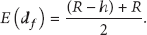
To find the closest nodes to the surface sink, we define a fitness factor α which reflects a candidate node's appropriateness to be the next hop. If a node obtains a relative small α, it means that the node is near enough to the sink node and appropriate to relay packets. We also take the energy balance issue into account in order to prolong the lifetime of the whole networks. If a node's energy level is lower than a predefined threshold it will not forward packets in a period of interval. In addition, because a node will consume much more energy to send a packet than to receive a packet [15], we use overhearing technology to reduce the sending actions whenever possible.
3.2. Protocol Description
3.2.1. Parameter Definition
We introduce the notion of fitness factor to measure the suitableness of a node to be the forwarder. According to this parameter, we can decide the priority of a node to forward packets. An example is shown in Figure 1.

Fitness factor.
Source node

We regard the nodes which are not only in a sender's communication range but also closer to the sink node as the neighbor nodes. That implies that we take no account of the sender's adjacent nodes whose distances to the sink node are farther than that of the sender. This is why we append the limitation
In Figure 1, there are two arcs
3.2.2. Data Forwarding
We mainly use the broadcast technology to forward data packets. Like other broadcast protocols, RDBF also does not need forwarders to transmit some control messages before broadcasting data packets. In other words, if a node has data packets to send and it meets the requirements of RDBF, it can instantly broadcast. To reduce the energy consumption, overhearing technology is used whenever possible. As a result, the acknowledge messages are also unnecessary in most cases.
Without controlling messages exchanging, a data packet will naturally include more information. In a packet, there are two fields, SP and FP, that is, the coordinates of the sink node and the forwarder. Once a node receives a data packet, it will check these two positions and calculate the distance to the sink d and the distance to the forwarder
Although the
Figure 1 is also feasible to describe how to make the decisions about data forwarding. Here source node
Progress of data forwarding.

We also consider the energy balance issue to prolong the whole networks' lifetime. Each node maintains a residual energy value. According to the service time of the networks, a periodic residual energy threshold will be written into the packets. Once a node receives a packet it will compare its residual energy value with this threshold. If its energy level is below this threshold, it will stop forwarding packets for an interval until receiving a packet with a lower energy threshold. In this mechanism, we can avoid draining individual nodes' energy too early.
3.3. Theoretical Analysis
RDBF always selects proper candidate forwarders in an approximate spherical segment region. When the node density is fixed, the larger the region is, the more the nodes going to be candidate relay nodes are. When we consider the 3D situation, the volume of the region is directly related to the fitness factor and the transmission range of the sensor nodes. The section of the scene is shown in Section 3.3.1. In Figure 2, sensor nodes in the upper hemisphere are approximately considered closer to the sink node than the previous forwarder or the source node. However, we introduce a fitness factor, which is used to limit the number of candidate nodes. After that, the candidate region is limited in the dash area

The region of the candidate forwarders.
3.3.1. The Candidate Region
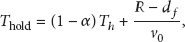
The area of 
When we fix the minimum allowed fitness factor as 
Actually, the volume calculated above is not the exact volume of the candidate region, which should not include the
We build a coordinate system in Figure 2 and draw two circles (arc 
The arc 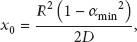
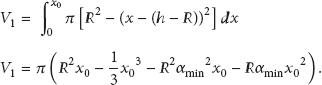
The arc 
With the two volumes 
This calculated value above is the volume of the additional region which is included in V calculated in (4). In fact, this volume is the difference between the volume of the actual candidate region and the calculated approximate volume. We can indicate that 
In (10), r can reflect the ratio of the volume of the addition region and the volume of the approximate region calculated in (4). In order to expound this issue clearly, we assume that the D is five times longer than the R, which is almost the end-to-end distance, and fix the
In the following analysis, we directly use the volume value V to replace the volume of the candidate region.
3.3.2. The Transmission Efficiency of RDBF
We denote the density of the sensor nodes as 
The RDBF transmits data packets in a hop-by-hop model and it always sends packets to the farthest downstream neighbor node. In Figure 2, we can see that the distance between the sender and the next relay node is in the range of 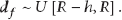
The expected value of the forward distance is
When the source node has packets to send to the sink node and the distance between the two nodes is D, the average hop count 
Because RDBF introduces a priority mechanism, the candidate node with the highest priority level can send the received packets first. As long as there is one node which can forward the packet, the transmission is successful. That is to say, the probability that a packet can be sent to the next hop node is 
Using the equations defined above, we can estimate the packet delivery ratio (PDR) of the RDBF protocol. For example, the transmission R is 20 m, the distance from the source node to the sink node D is 150 m, and the maximum allowed fitness factor is
3.3.3. The Energy Consumption Model
RDBF is a multihop forwarding routing protocol, according to the different hop counts to the sink, underwater nodes can be approximately divided into several round layers centered to the sink. That is to say, underwater nodes with the same hop count to the sink are in the same round layer, just like that shown in Figure 3. In the actual three-dimension situation, the number of nodes in layer 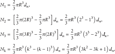
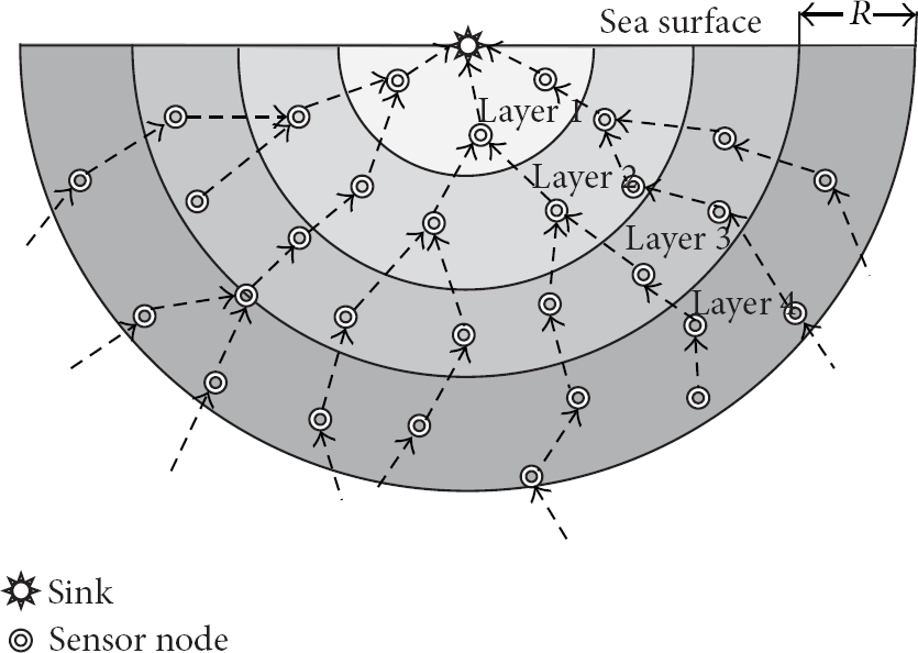
Communication model of the multihop routing.
If the probability one node creates a packet in a unit time is P, the total number of packets created in layer 
It is clear that the bigger the layer number k is, the more the packets (
The energy used to forward a packet is defined as 
In each of the above formulas in (18), n is the number of layers. And the total energy consumption 
From the above equations from (17) to (19), we can estimate that energy consumption of the networks depends on the number of layers. In fact, sensor nodes which lie in the same layer approximately obtain the same hop count to the sink. The number of layers is directly related to the biggest hop count of the networks. According to (14), the average end-to-end hop count is
As mentioned earlier, the distances of the forwarders to the sink are the shortest and the hop count of routing paths consisted by these beneficial nodes are minimum, which is the main contribution of the RDBF. In a word, RDBF always tries to forward packets to the sink as far as possible in each hop, which can distinctly reduce the total energy consumption of the underwater wireless networks.
In the next section, we conduct a series of experiments to evaluate the performance of the RDBF protocol. The simulation results demonstrate that the theoretical analysis is valid and referable. To verify the correctness of the theoretical result, we set the simulation environments corresponding to the theoretical parameters as much as possible. When all the simulation environments are similar to the parameters used in the theoretical analysis, the experiment results fit the theoretical values well.
4. Performance Evaluation
In this section, we evaluate the performance of our proposed RDBF protocol through extensive simulations in Aqua-Sim [16] which is an NS-2 based simulator. To explicitly describe the performance of RDBF, we compare it to a well known routing protocol VBF.
4.1. Simulation Environments
In our simulations, sensor nodes are deployed uniformly in a space of
4.2. Simulation Metrics
We evaluate the performance of our protocol with three interesting metrics.
4.2.1. Packet Delivery Ratio (PDR)
We measure the PDR of the sink node to evaluate the reliability. In a simulation, the source node sends 200 packets to the sink node in total; the proportion of the number of received packets by the sink node is defined as packet delivery ratio.
4.2.2. Average End-to-End Delay
Each packet contains a time stamp when it is generated by the source node. When the sink node receives the packet, it will use the current time to minus the time stamp to get the end-to-end delay. The average delay time of all the successfully received packets is defined as average end-to-end delay.
4.2.3. Energy Consumed
We compute the total energy that the network consumed during the simulation to evaluate the energy efficiency of our protocol.
4.3. Simulation Results
We first consider the impact of node density and mobility on our protocol. Then we investigate the impact of fitness factor.
4.3.1. Impact of the Node Density
In the first set of experiments, we compare the three metrics with varying node densities. The speed of nodes is set as 2 m/s. The fitness factor of RDBF is fixed as 0.5, while the desirableness factor and radius of VBF are set as 1.0 and 20 m, respectively. The number of nodes deployed in the network is from 500 to 1500 with an increment of 200. Figures 4, 5, and 6 plot the PDR, average end-to-end delay, and energy consumed versus number of nodes, respectively.

PDR under varying densities.

Average end-to-end delay under varying densities.

Energy consumed under varying densities.
The PDR of our proposed protocol is always higher than that of the VBF, especially in the sparse network, which is shown in Figure 4. When there are only 500 nodes in the network, the PDR of VBF is below 0.45 and the PDR of RDBF is over 0.55. When the number of nodes increases to 700, the PDR of RDBF can reach 0.8, while the PDR of VBF is even below 0.65. Our RDBF's PDR is over 0.9 when there are more than 1200 nodes. This is because VBF can only select the nodes in a narrow area (routing pipe) as the relay nodes. When the node density is small, VBF probably cannot find a path from the source node to the sink node. While RDBF is free of that limit, it can select from more candidate nodes. So our RDBF is more likely to find a valid routing path to the sink node.
The average end-to-end delay of RDBF is distinctly shorter than that of the VBF, which is shown in Figure 5. This is because RDBF always finds the nodes nearest to the sink node as the forwarder, so that the hop count in a routing path is minimal. In VBF, the candidate nodes are near the routing vector, but hop count of a routing path may not be small. The end-to-end delay can be considerably long when a packet goes through too many hops. As the increase of the node density, both protocols' end-to-end delays are decreasing. This is because, when the node density is large enough, a node has more neighbor nodes. Then both RDBF and VBF can choose a more proper node as the forwarder, which decreases the hop count of a routing path. The less hop count can directly shorten the end-to-end delay.
However, our RDBF protocol consumes a little more energy than the VBF in the simulation, which is shown in Figure 6. This is because there are more nodes involved in the selecting forwarders process in RDBF. But such a little more energy is worth consuming to obtain the great performance in PDR and end-to-end delay. And, with the increase of the node density, the network consumes more energy; this is also because there will be more nodes involved in the forwarding process.
4.3.2. Impact of Mobility
In the second set of experiments, we investigate the three metrics with the varying different node speeds. We deploy 1300 nodes in the network space. Other factors are the same as the first set of experiments. We vary the node speed from 0 m/s to 3 m/s with an increment of 0.5 m/s. Similarly, Figures 7, 8, and 9 plot the PDR, average end-to-end delay, and energy consumed versus speed of nodes, respectively.

PDR under varying speeds.

Average end-to-end delay under varying speeds.

Energy consumed under varying speeds.
In Figure 7, we can see that the PDR of RDBF is always higher than that of the VBF. When the speed is 0 m/s, that is, the network topology is static, the PDR of both protocol is 1. But in some cases once the nodes are deployed, if there is no path to the sink at the beginning the packet delivery ratio will keep being 0. While the nodes start to move in the network, the routing paths will change frequently. Each packet may choose an absolutely different path to reach the sink node. On some special occasions, the mobility can lead to a scenario that there is no desirable neighbor node for a relay node to forward packets. Therefore more forward failures occur in the motional network than the static situation.
On the other hand, when the speed of nodes is fast enough, the forward failure can be revised immediately. This is because other nodes around the failure region can move there to be a desirable forwarder before the next packet arrives there. That is why the PDRs of both protocols are slightly higher when the speed is faster, which is shown in Figure 7.
The average end-to-end delay and energy consumed of both protocols are not obviously influenced by the mobility of nodes.
The end-to-end delay is only associated with the successfully received packets instead of all the packets sent into the network, which cannot be impacted by the varying PDRs. Once the nodes density is fixed, the hop count of each routing path is almost invariable. Regardless of the speed of nodes, the end-to-end delay is changeless. As a result, we can observe two smooth curves in Figure 8.
The energy consumed is also closely related to the node density instead of the speed of nodes. When the network is mobile, the energy consumption is kept in a relatively stable level. This is because the number of nodes involved in the forwarding process is similar. The result is shown in Figure 9.
4.3.3. Impact of the Fitness Factor
In the last set of experiments, we only use the RDBF protocol to investigate the three metrics with varying fitness factors. Because VBF does not have the fitness factor, the compared experiments are unconvincing. In RDBF, the fitness factor is a key argument to judge a node's fitness to be a relay node. This parameter is in a range of
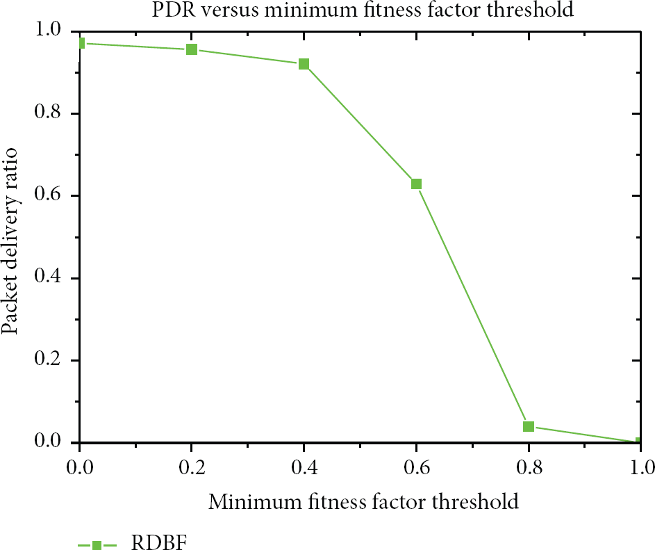
PDR under varying minimum fitness factors threshold.
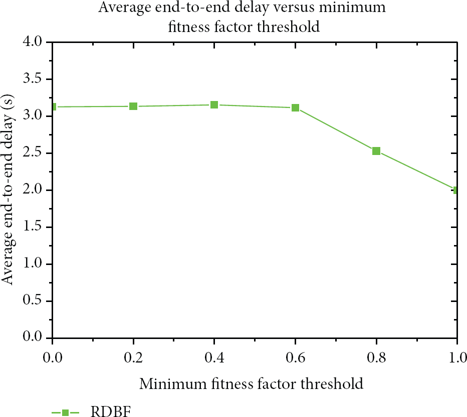
Average end-to-end delay under varying minimum fitness factors threshold.

Energy consumed under varying minimum fitness factors threshold.
PDR of the RDBF is obviously affected by the varying fitness factor which can be seen in Figure 10. When the parameter threshold
In fact, when the minimum fitness factor threshold is 1, the sink node cannot receive packets from the source. But we still consider that the end-to-end delay is 2 seconds at this moment, which is equal to one of the simulation environments that the source node send one data packet per two seconds. When the threshold value is above 0.6, the delay continuously decreases. This is because, when the threshold is very large, as long as there is a path, it must be an extremely optimal path, so that the end-to-end delay is accordingly short. While the minimum threshold is below 0.6, the limit to the candidate nodes becomes fairly loose and the end-to-end delay holds in a maximum value. The average end-to-end delay result is shown in Figure 11.
The energy consumption is associated with the number of nodes involved in the network affairs. When the threshold of the fitness factor is increasing, fewer nodes will be involved in the forwarding process. As a result, from Figure 12, we can see that the total energy consumed continuously decreases as the minimum fitness factor threshold increases.
5. Conclusions
In this paper, we proposed a relative distance based forwarding routing protocol (RDBF) for the underwater wireless sensor networks. RDBF always tries to find an optimal routing path from the source node to the sink node. To measure the fitness of a node to be the relay node and limit the number of nodes involved in the forwarding process, we employ a fitness factor. RDBF only allows the nodes whose fitness factors are below a threshold to participate in forwarding packets. In addition, we take the residual energy of the sensor nodes into account in order to balance the energy consumption. RDBF also controls the transmission time of the multiple forwarders to reduce the duplicates of the packets. The simulation results show that, in different node densities and mobile scenarios, the performance of the RDBF is superior to the well known VBF protocol in average end-to-end delay and packet delivery ratio aspects. And the energy efficiency of the RDBF is approximate to that of the VBF.
Footnotes
Conflict of Interests
The authors declare that there is no conflict of interests regarding the publication of this paper.
Acknowledgments
This work is supported by the National Natural Science Foundation of China under Grant no. 61073047, Fundamental Research Funds for the Central Universities: HEUCFT1202, HEUCF100609, and Harbin Special Funds for Technological Innovation Talents: 2012RFLXG023; all support is gratefully acknowledged.