
Abstract
Braided pneumatic muscle actuator shows highly nonlinear properties between displacements and forces, which are caused by nonlinearity of pneumatic system and nonlinearity of its geometric construction. In this paper, a new model based on Bouc-Wen differential equation is proposed to describe the hysteretic behavior caused by its structure. The hysteretic loop between contractile force and displacement is dissolved into linear component and hysteretic component. Relationship between pressure within muscle actuator and parameters of the proposed model is discussed. A single degree of freedom manipulator actuated by PMA is designed. On the basis of the proposed model, a novel cascade position controller is designed. Single neuron adaptive PID algorithm is adopted to cope with the nonlinearity and model uncertainties of the manipulator. The outer loop of the controller is to handle position tracking problem and the inner loop is to control pressure. The controller is applied to the manipulator and experiments are conducted. Results demonstrate the effectiveness of the proposed controller.
1. Introduction
1.1. Review of Modeling and Control of PMA
Pneumatic muscle actuator (PMA, shown in Figure 1(a)) has been attracting scientists’ attention in the past two decades. Several names in the literature are synonymous with PMA, such as Mckibben muscle [1–3], air muscle, rubber actuator, fluidic muscle [4], or a biomimetic actuator [5]. PMA has been widely used in medical and industrial robotics because of their unique advantages such as high power-to-weight ratios, compliance, and low cost of manufacture compared to electric motors and pneumatic cylinders [6, 7].

(a) Photograph of commercial PMA and (b) working principle of PMA.
Air is transported into the rubber bladder through an inlet located at one end cap and thus the soft tube is inflated. Due to constraints of fiber mesh, the latex tube expands in radius direction and shortens in longitudinal direction. If mechanical load is attached to the other end cap, it will be driven to move along the axial direction of the PMA (shown in Figure 1(b)). Despite attractive advantages, PMA has some shortcomings. It only exerts force along its contractile direction and maximum contractile ratio is generally less than 25%, which means relatively small journey compared with its nominal length. However, one of the most important disadvantages is its high nonlinear property between its contractile force and displacement. The high nonlinearity is caused by nonlinearity of pressurized air and the geometric features of the PMA.
Various models have been developed to describe mechanical property of PMA. Chou and Hannaford [8] proposed a famous brief model based on geometrical relationship with several assumptions. Researchers made improvements in Chou's model by accounting for other factors such as noncylindrical ends, friction between strands, and elastic force applied by latex bladder. Kothera et al. [9] thought of noncylindrical shape of terminal ends as a circular arc and treated it as a correcting factor during actuating process. The elasticity of the bladder has been considered by employing Mooney-Rivlin model to describe energy stored in rubber tube [10, 11]. Friction between strands has been thought to be the main cause of hysteresis in force-length curve in isobaric experiments. Tondu and Lopez [12] developed an expression to calculate the friction. Modeling from phenomenological behaviors of PMA has been adopted by several researchers. Van Damme et al. [13] proposed a Preisach-based model to describe hysteresis in pleated PMA. Minh et al. [14] constructed a hysteresis model based on Maxwell-slip theory to improve the accuracy of the model.
To handle the nonlinear characteristics inside PMA, various control methods have been proposed. Gain schedule method was adopted to handle the nonlinear factors in PMA by Repperger et al. [15]. The discrete time PID controller combined with a feed-forward was used to control PMA [16]. A sliding mode in [17] was proposed to tackle the position tracking problem. A switching control approach using learning vector quantization neural networks was designed to compensate external load disturbances in [18]. Tondu and Lopez compared the performance of a fixed fuzzy controller and that of variable structure controller in a PMA system [12]. They thought variable structure controller was more superior in coping with high nonlinearities of PMA system.
As the basic element of neural networks, neuron has the ability of self-adaptability according to learning rules. It is also simple in calculation and has the potential in online application. If the single neuron is combined with conventional PID strategy, the novel algorithm would own powerful capability of self-learning and self-adaption, which is helpful to cope with high nonlinear and uncertain plants. In this research, single neuron adaptive PID is employed to control a 1-DOF manipulator actuated by PMA.
1.2. Single Degree of Freedom Manipulator Actuated by PMA
The designed manipulator is shown in Figure 2. PMA in this setup is type DMSP-20-120RMCM with an internal diameter of 20 mm and a length of 120 mm. PMA supplies the rotary torque for the link and the spring drives the link back to its equilibrium position. Pressure sensor samples the pressure inside PMA and position sensor supplies the displacement information of PMA. Both pressure information and position information are transformed to data acquisition card for closed loop control. Gas is produced by air compressor and transported to PMA through pipe. Amount of the gas to PMA is controlled by proportional regulator. Digital control signal produced by data acquisition card is used to control the proportional regulator. Components of the manipulator are listed in Table 1. Compared to manipulators actuated by an antagonistic pair of PMAs, the devised manipulator in this paper reduces its cost because only one PMA is employed. The manipulator is high nonlinear not only due to complex properties of pneumatic system but also due to the high nonlinearity of PMA. To improve the performance and tracking accuracy of the manipulator, control algorithm should be studied. Equation (1) is easily acquired using Newton's theorem. Consider

where J is the moment of inertia, f [N] is PMA force, K [N/m] is the stiffness coefficient of spring, r [m] is the radius of rotary base, θ [rad] is the angular displacement, and X [m] is the contractile length of PMA.
Components of the 1-DOF manipulator.


Single degree of freedom experimental setup actuated by PMA.
1.3. Organization of This Paper
This paper proposes a novel model based on Bouc-Wen equation. In comparison with previous modeling methods from point of working mechanism, Bouc-Wen model avoids the geometric parameters (such as length of single fiber thread and braided angle), which are hard to be accurately measured. Bouc-Wen equation has a much more compact form, which is important in actual controller design and real-time calculation. In previous phenomenological models mentioned above, complete velocity independence is assumed, although this was not true because frictional force within PMA varies with velocity of PMA [19]. However, the influence of PMA's velocity is considered in Bouc-Wen model; that is why Bouc-Wen model is selected. On the basis of the model, a novel cascade controller is devised. Single neuron tuned PID algorithm is adopted to deal with nonlinear properties and modeling uncertainties.
This paper is organized as follows. Section 2 seeks to model the nonlinear properties among actuating force, contractile length, and pressurized pressure using Bouc-Wen model. Section 3 designs a novel model-based cascade position PID controller. Parameters of the controller are automatically tuned by single neuron algorithm, which enhances the adaptability of the controller. The outer loop of the controller is to cope with position tracking problem whilst the inner loop is to realize pressure control. Experiments are designed to validate the proposed cascade controller in Section 4. Section 5 concludes this research.
2. Modeling Nonlinear Behaviors of PMA
2.1. Modeling Methodology
2.1.1. Bouc-Wen Model
The Bouc-Wen model, shown in Figure 3, introduced by Bouc [20] and extended by Wen [21], has been widely used in describing hysteretic behavior of materials, structural elements, and piezoelectric actuators in past years because of its capacity of matching the behavior of a wide class of hysteretic systems. The Bouc-Wen model consists of a set of equations given as
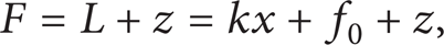

where F is the contractile force in this paper, k is the stiffness coefficient of spring, and f0 the initial force in initial conditions. Parameters in (2b) have different functions on shaping the hysteresis curve: α controls the contracting force amplitude, β and γ control the shape of hysteresis loop, and n controls the smoothness of the transition from elastic to plastic response. In this research n is assumed to be 2 based on the observation of experimental contractile force-displacement curves. In this paper (2a) and (2b) are adopted to portray the hysteretic behavior of PMA, so parameters k, f0, α, β, and γ need to be identified. Actually, the hysteretic loops are different in shape as pressure in PMA varies, which indicates that relationship between these parameters and pressure applied to PMA may exist. The relationship would be discussed via experiments.

Hysteresis model based on Bouc-Wen theory.
2.1.2. Parameter Identification Method Using Least Square Method
In identification of Bouc-Wen model parameters, numerical optimization techniques have been widely used, one of which is least square method. To identify parameters in (2a) and (2b), force-displacement hysteretic loop acquired from experiments is dissolved to linear component and hysteretic component (shown in Figure 6). Parameters k and f0 in linear component are fitted by using the least squares curve fitting tools in Matlab. By subtracting the linear component force from total contractile force, hysteretic component force is acquired which would be characterized by Bouc-Wen differential equation. To obtain optimal values of δ, β, and γ, Runge-Kutta algorithm depicted in (3) is incorporated in least squares curve fitting method. Consider

where
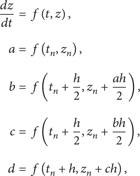
where z
n
is the value of the variable at time t
n
, h is the length of time interval [t
n
, tn + 1], and f is the varying rate of z. With initial condition z(0) = z0 the Runge-Kutta algorithm takes z
n
and t
n
and calculates the approximated value for zn + 1 at instant of tn + 1. In this research, the varying rate f is expressed in (2b) and the velocity values

where z ei is the ith experimental data. By searching the minimum value of E, parameters α, β, and γ would search for their optimal values.
2.2. Experiments and Discussion
2.2.1. Experimental Setup
In order to identify the parameters of the phenomenological model and experimentally validate the proposed hysteretic model, the schematic and photograph of the experimental setup are shown in Figures 4(a) and 4(b), respectively. In this apparatus proportional regulator tunes the amount of air flowed from air compressor to the pneumatic cylinder and PMA by controlling the voltage output from data acquisition card. Position sensor acquires the contractile length of PMA in real time. Gauge pressure sensor located at the air inlet of the actuator is used to record the air pressure applied to PMA. Load cell connected to the PMA provides information of contractile force. Data acquisition card transforms analog data acquired from position, pressure, and force sensors to digital form and then transports the digital data to computer. In this experiment, PMA manufactured by FESTO company is a DMSP-20-120RMCM type. According to the data sheet supplied by FESTO, this type muscle has a maximum contractile ratio of 25% at pressure of 0.6 MPa.

Experimental setup for testing PMA: (a) schematic diagram; (b) photograph.
2.2.2. Discussion about Relationship between Pressure in PMA and Parameters of Bouc-Wen Model
To obtain experimental data from the apparatus, air is applied to PMA and pneumatic cylinder, respectively. Predetermined constant pressure is transported to the PMA, and then sinusoidal waves of pressure with different frequencies and magnitudes are adopted to drive pneumatic cylinder to move. With the propel imposed by cylinder, PMA would be in a reduplicative motion of lengthening and shortening. Record the real-time contractile force by load cell, contractile length of PMA by position sensor, and pressure applied to PMA by pressure sensor at a 500 Hz sampling frequency, respectively, change the constant pressure inside PMA by rotating manual regulator, and repeat the experiment until the pressure is up to 600 KPa. Through the experiments, sets of data are acquired which would be used in the study of the relationship between pressure in PMA and parameters in Bouc-Wen model.
When sinusoidal waves of pressure with frequency 0.15 Hz and magnitude 0.35 MPa (shown in Figure 5(a)) are applied to pneumatic cylinder, the corresponding measured displacements and forces are recorded in real time and plotted in Figures 5(b) and 5(c). Based on the measured displacements and forces, parameters of the model are obtained as follows:
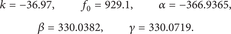
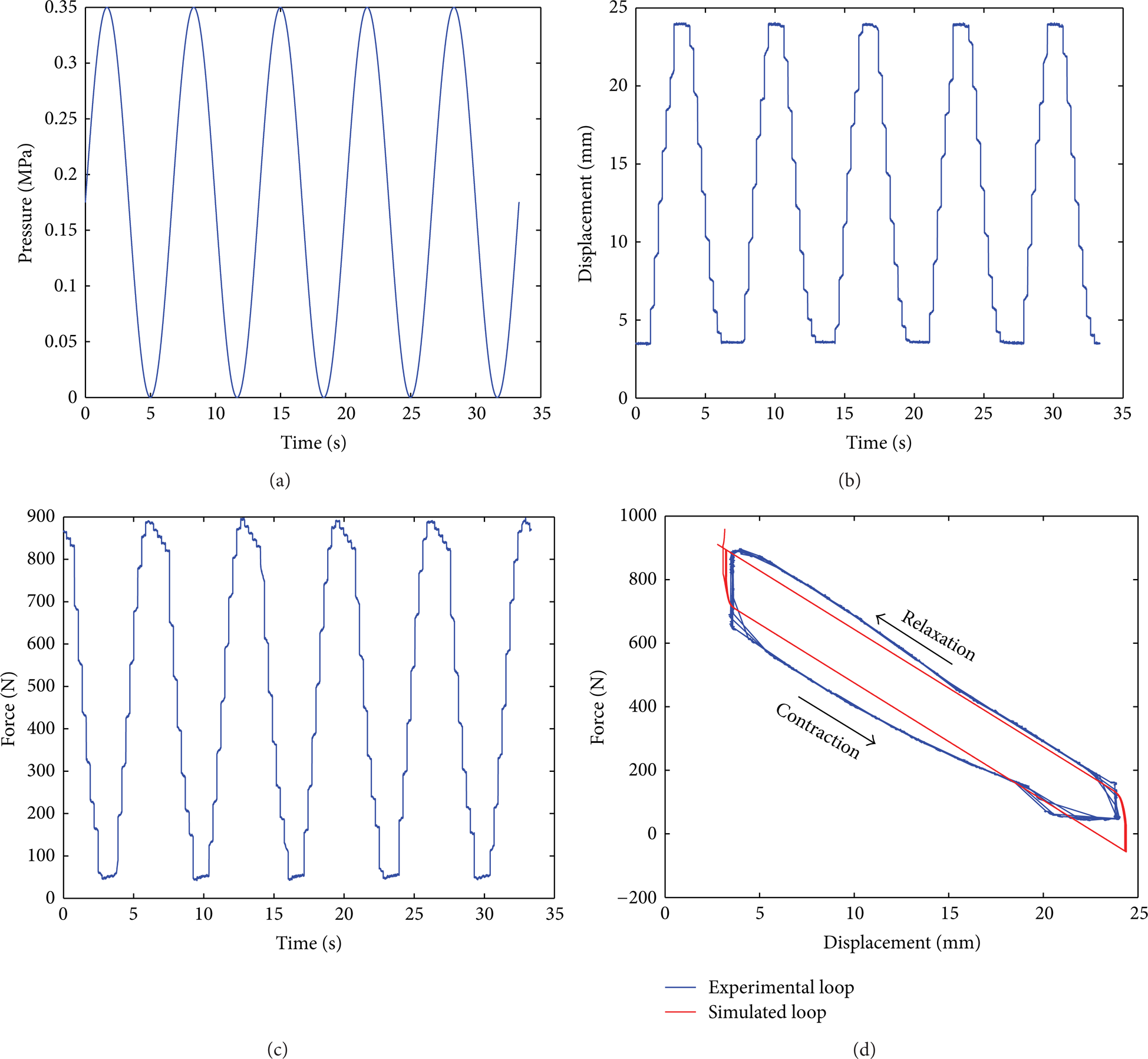
Time histories of the applied pressure to pneumatic cylinder, the measured output displacements and contracting forces, and the displacement/force hysteretic curve when pressure is 0.4762 MPa within PMA: (a) the applied pressure to pneumatic cylinder, (b) the output displacement, (c) the output contractile force, and (d) the hysteretic curve of the output displacement versus force.
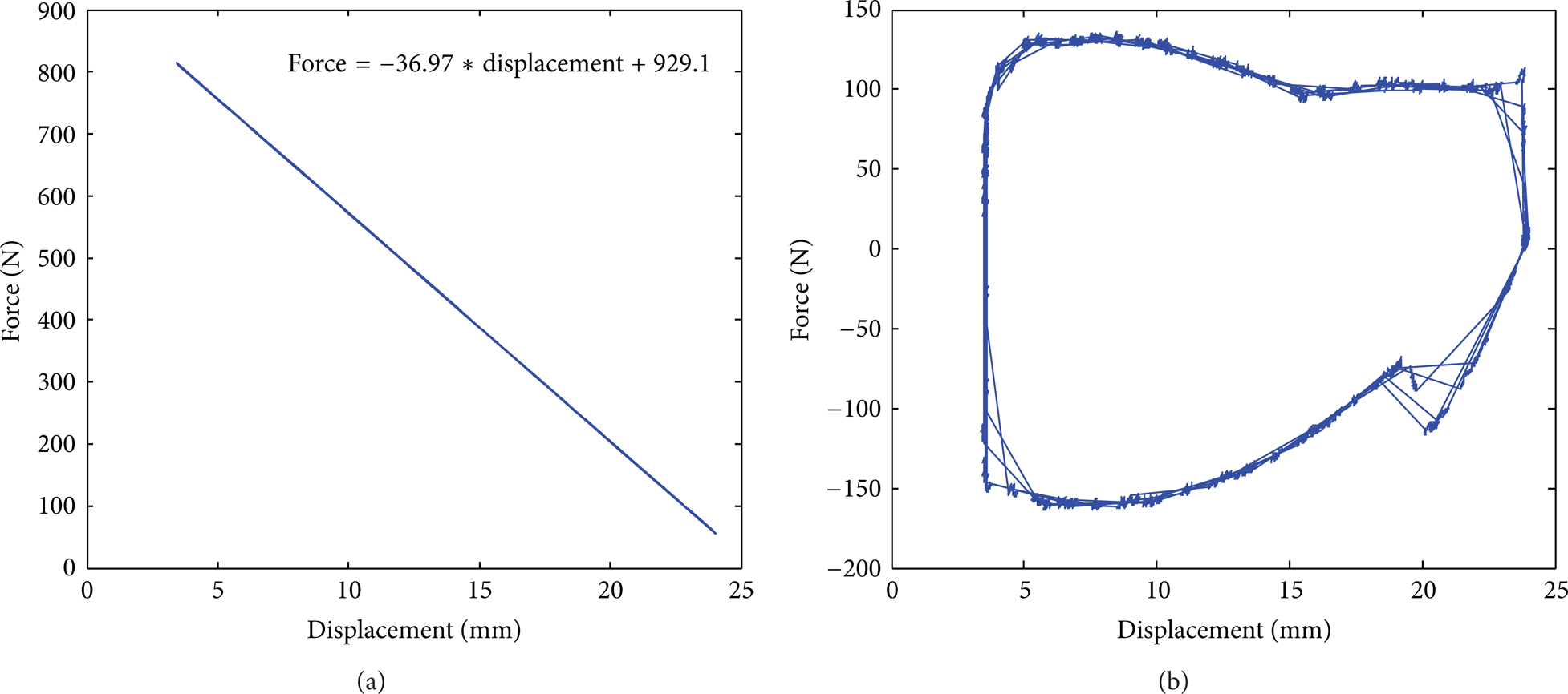
Linear and hysteretic components of the hysteretic curve when pressure is 0.4762 MPa in PMA: (a) the linear component and (b) the hysteretic component.
Comparison between experimental and simulated force/displacement loops in Figure 5(d) shows global agreement, although relative large errors occur at the lower end and lower half curve, which could be explained by the characteristics of Bouc-Wen differential equation. As well known, Bouc-Wen differential equation can only describe the symmetric hysteretic behaviors, while the experimental loop in Figure 5(d) is unsymmetric. Pressure in PMA is changed and corresponding displacement/force hysteretic loops are acquired in order to study the relationship between pressure and parameters in Bouc-Wen model. Based on these experimental loops, model parameters are calculated, and the relationship between pressure inside PMA and these parameters is fitted in quadratic polynomial equations as follows:

2.2.3. Predictive Capability of the Identified Model
To verify the predictive capacity of the identified Bouc-Wen model, sinusoidal waves of pressure with frequency 0.1 Hz and magnitude 0.37 MPa (shown in Figure 7(a)) are applied to pneumatic cylinder and constant pressure of 0.498 MPa is applied to PMA. Hysteretic force/displacement curves and corresponding predicted curves are plotted in Figure 7(b). Comparison between experimental and predictive curves indicates that the identified numerical model could portray the hysteretic behaviors of PMA.

Time histories of the applied pressure to pneumatic cylinder and the displacement/force hysteretic curves when pressure is 0.498 MPa in PMA: (a) the applied pressure to pneumatic cylinder and (b) experimental and predicted displacement/force hysteretic curves.
To validate the predictive capacity of this model, sinusoidal waves of pressure with frequency 0.3 Hz and magnitude 0.25 MPa (shown in Figure 8(a)) are applied to pneumatic cylinder when the PMA is at constant pressure of 0.304 MPa. Experimental displacements and forces are sampled and their relationship is plotted in Figure 8(b). Comparison between experimental and predictive curves shows the model's capability of predicting the contractile force of PMA based on sampled displacements and pressure of PMA.

Time histories of the applied pressure to pneumatic cylinder and the displacement/force hysteretic curves when pressure is 0.304 MPa in PMA: (a) the applied pressure to pneumatic cylinder and (b) experimental and predicted displacement/force hysteretic curves.
3. Cascade Position Controller Design for Single Degree of Freedom Manipulator
3.1. Single Neuron Adaptive PID Control Design
The single neutron adaptive PID algorithm can achieve more robust performance than conventional PID controller because of its capacity in self-learning and self-adaptability. Using some certain self-adjusting method, single-neutron adaptive PID tunes its PID parameters automatically during the control process. The architecture of single-neutron is illustrated in Figure 9. The input of the transformer is the error between reference point and sampled value, whilst the outputs of the transformer are the state variables x i (i = 1, 2, 3). In incremental PID algorithm, x i has the following values:

w1, w2, and w3 in Figure 9 are in accordance with proportional, integration, and derivative parameters of PID algorithm. Usually, w i (i = 1, 2, 3) are trained by some learning rules, most popular of which is the hybrid of supervisory delta learning rule and nonsupervisory Hebbian rule. A cost function shown in (9) is defined to validate the performance. Consider
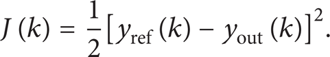

Diagram of the single neuron PID controller.
The task of learning algorithm is to reduce J(k) by adjusting weights w1, w2, and w3. Thus, the weights are modified as follows:

where η i (i = 1, 2, 3) are learning rates of the neuron. The gradient of J(k) with respect to w i is calculated as follows:

Actually, ∂yout/∂u is often difficult to obtain because of the complexity of plant. To simplify the problem, it is approximately replaced by a symbol function sgn[∂yout/∂u]. The inaccuracy caused by the approximation operation is compensated by adjusting learning rate η i . Many applications demonstrate that the error variable e(k) is the main factor influencing the process of online tuned weight parameters, so x i in (11) are replaced by Δe(k) + e(k).
To ensure the astringency and robustness of the control method, learning algorithms should be disposed canonically. The summarized learning algorithms are listed in (12). Consider

3.2. Inner Loop for Pressure Control
Pressure building-up process within PMA is highly nonlinear not only due to nonlinearity of PMA but also due to high nonlinear features of pneumatic system. The flow dynamics through valve orifice of pressure regulator is depicted by three equations: a chamber continuity equation, an orifice flow equation, and a force balance equation of the spool. These three equations are listed in detail in [22]. However, parameters of pressure regulator are difficult to acquire. The other challenge is to model the high nonlinear pressure building-up process within PMA. This may be achieved by polytropic gas law. However, in our previous research we found that it is difficult to acquire the muscle volume during the charging and discharging process. This is because of variation in volume and shape of PMA's inner tube. If the modeling process is difficult to achieve, a better choice is to use nonparametric intelligent controller in regulating pressure control. Single neutron is adopted in this paper to cope with high nonlinear pressure building-up process. The schematic could be depicted by Figure 9, where yref represents the desired pressure pref, yout represents the output pressure pout, and “Plant” refers to PMA.
3.3. Outer Loop for Position Control
Equations listed above form the model basis for position control. The cascade position control scheme is plotted in Figure 10. Single neuron PID algorithm is to cope with model discrepancy and nonlinearities inside PMA. The complex frictional force, flexibility of the steel wire, and other uncertainties are also dealt with by the adaptive PID controller. From Figure 10 we find that the desired torque is the output of the outer loop and then used to calculate the desired pressure. Parameters w i (i = 1, 2, 3) are online tuned according to learning algorithm. Actually, when programming learning rules in C++ code, amplitude limitation on the output of the outer loop controller should be set. This is because of the fact that sampling errors may occur and circumstance disturbances exist, so is the output of the inner pressure loop controller. The function P(τ, x, v, a) in Figure 10 is used to acquire the desired pressure for inner loop.
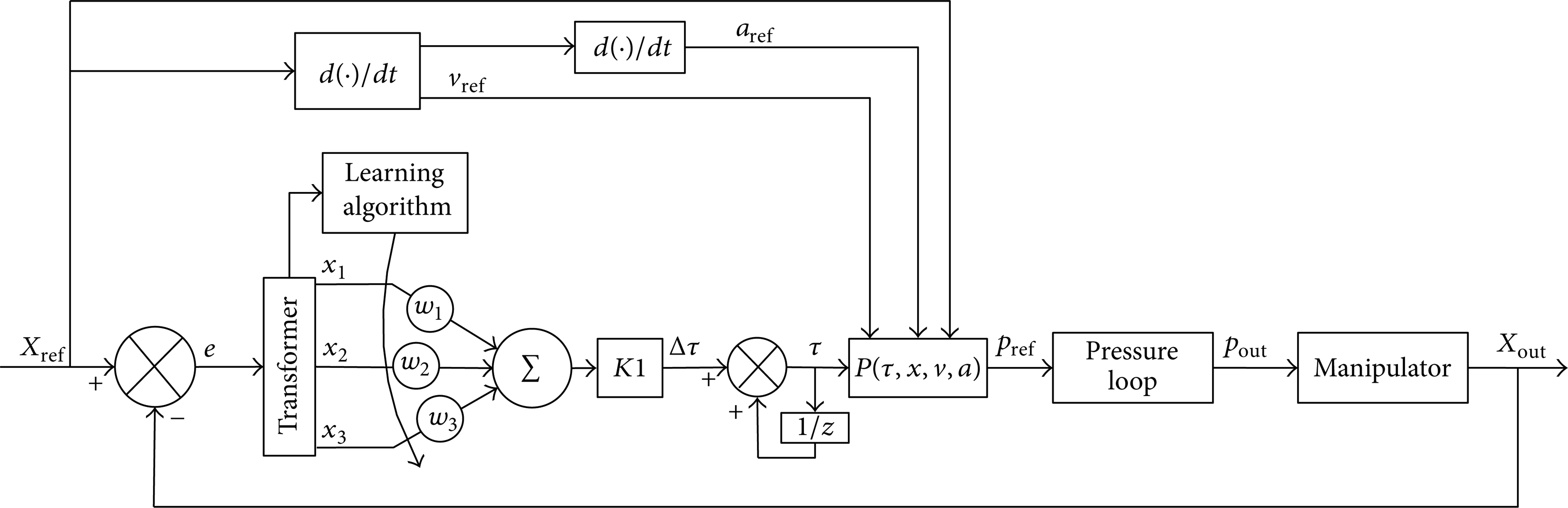
The scheme of the cascade position control of the manipulator.
4. Experiments and Discussions
To verify the effectiveness of the proposed novel controller for the single degree of freedom manipulator, experiments are performed. The experiments are divided into two types. The first one is to validate the inner pressure control algorithm for pressure control whilst the second experiment type is to validate the cascade position controller.
4.1. Validation of Single Neuron PID Algorithm for Pressure Loop
Figure 11 shows experimental curves acquired from single neuron PID algorithm and classic PID algorithm under the input command of square wave with frequency of 0.1 Hz and magnitude of 0.5 MPa. From the curves we find that the rising times of the two response curves are almost identical. The value of the rising time is about 0.6 (s). However, after rising stages the response of single neuron PID algorithm shows better performance than that of classic PID controller. The oscillations in the response curve of classic PID controller are much larger than those in response from single neuron PID controller. The maximum overshoot of 4% occurs in the response of classic PID controller while the maximum overshoot of 0.7% occurs in the experimental curve of single neuron PID controller. The comparison between pressure tracking errors of the two controllers is depicted in Figure 12, from which the superiority of the single neuron PID algorithm is also demonstrated. In time interval [0.6, 5] (s), oscillations happen both in the two curves. This is due to the fact that the PMA is in maximum contractile state and the spring vibrates slightly. The volume of PMA varies along with the vibration of the spring and the pressure inside PMA oscillates. Variance of parameters of single neuron PID controller w1, w2, w3 are plotted in Figure 13. Values of parameters w1, w2, and w3 of classic PID controller are 2.0, 0.8, and 5.0, respectively. The initial values of w1, w2, and w3 of single neuron PID controller are also 2.0, 0.8, and 5.0, respectively.

Comparison between response of single neuron PID controller and that of classic PID controller for pressure loop.
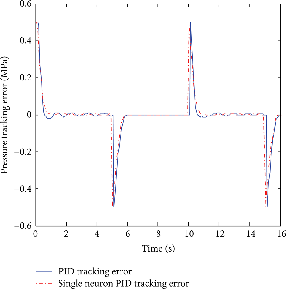
Pressure tracking error of classic PID controller and single neuron PID controller.

Variance of parameters of single neuron PID controller w1, w2, and w3 under square excitation of 0.1 Hz and amplitude of 0.5 MPa.
4.2. Validation of Single Neuron PID Algorithm for Position Loop
To show the capacity of the novel controller in position tracking, square trajectory excitation and sinusoidal trajectory motion are applied to the single degree of freedom manipulator. Experimental responses of the proposed cascade controller are plotted in the following figures. Experimental response curves of classic PID controller are also plotted so as to compare with the curves of single neuron PID controller. Figure 14 shows the experimental data of the single neuron PID controller under the square excitation with frequency of 0.1 Hz and magnitude of 15 mm. Responses of classic cascade PID controller are also plotted. Classic cascade PID controller here means the outer loop adopted classic PID algorithm while the inner pressure loop uses single neuron PID algorithm. Rising time of the single neuron PID controller is about 1.5 (s). This value is close to the rising time of classic cascade PID controller (1.44 (s)). The performance of the proposed single neuron PID controller during steady state is much better than that of classic cascade PID controller. The maximum overshoot of 31% occurs in response curve of the classic controller while only 1.9% maximum overshoot happens in the experimental curve of the proposed single neuron PID controller. Response of the proposed novel cascade controller achieves steady state very fast while the position curve of classic cascade controller keeps vibrating. This is due to the adaptive capacity of single neuron in automatically tuning parameters of PID algorithm. At descending stage, the curve of single neuron PID controller descends much faster than classic PID response. The position tracking error curves are shown in Figure 15. By comparing the two error curves, the effectiveness of the novel controller is further verified. The enlarged view for portion A of Figure 15 shows that steady state error of single neuron error in time interval [1, 5] (s) is much smaller than that of classic PID controller. The enlarged view for portion B of Figure 15 demonstrates better performance of single neuron PID controller than classic PID controller during [6, 10] (s). Figure 16 shows the desired pressure and corresponding response using the single neuron PID algorithm. The pressure response is lagged behind the reference pressure because of time-delay characteristics inside PMA and pneumatic system. Figure 17 shows the variance of parameters of single neuron PID controller. Initial values of parameters for outer loop are 1.1, 1, and 0.01, respectively. The initial values of parameters for inner loop of single neuron PID controller are 0.8, 0.5, and 3, respectively. Values of parameters for outer loop of classic cascade PID controller are 1.1, 1, and 0.01 and parameters for the corresponding inner loop are 0.8, 0.5, and 3, respectively.

Comparison between responses of the single neuron PID cascade position controller and that of classic PID cascade controller under a square wave of 0.1 Hz with amplitude 15 mm.

Comparison between position tracking errors of classic PID controller and that of single neuron PID controller under square excitation of 0.1 Hz and amplitude of 15 mm.

Inner desired pressure loop and responses of single neuron PID pressure controller under square excitation of 0.1 Hz and amplitude of 15 mm.

Variance of parameters of single neuron PID controller w1, w2, w3 under square excitation of frequency 0.1 Hz and amplitude of 15 mm. (a)–(c): outer position single neuron PID parameters w1, w2, w3, respectively; (d)–(f): inner pressure single neuron PID parameters w1, w2, w3, respectively.
Figure 18 shows comparison between responses of the single neuron PID cascade position controller and that of classic PID cascade controller under a square wave of 0.1 Hz with amplitude 20 mm. Maximum overshoot of 11.94% occurs in the experimental curves of classic cascade PID controller. Position tracking errors are plotted in Figure 19. Calculated pressure for inner loop and pressure response are shown in Figure 20. Parameters for outer loop of single neuron PID controller (Figure 21) w1, w2, and w3 vary from their origin values 1.1, 1, and 0.01, respectively. The initial values of w i (i = 1, 2, 3) for inner pressure loop are 0.8, 0.5, and 3, respectively. Parameters of classic cascade PID controller equals to initial values of its corresponding parameters in single neuron PID controller. Figures 22 and 26 further verify the superiority of the proposed novel cascade controller. Corresponding tracking errors, inner pressure tracking loop, and variance of control parameters are also shown in Figures 23, 24, and 25 and Figures 27, 28, and 29, respectively.

Comparison between responses of the single neuron PID cascade position controller and that of classic PID cascade controller under a square wave of 0.1 Hz with amplitude 20 mm.

Comparison between position tracking errors of classic PID controller and that of single neuron PID controller under square excitation of 0.1 Hz and amplitude of 20 mm.

Inner desired pressure loop and responses of single neuron PID pressure controller under square excitation of 0.1 Hz and amplitude of 20 mm.

Variance of parameters of single neuron PID controller w1, w2, w3 under square excitation of frequency 0.1 Hz and amplitude of 20 mm. (a)–(c): outer position single neuron PID parameters w1, w2, w3, respectively; (d)–(f): inner pressure single neuron PID parameters w1, w2, w3, respectively.

Comparison between responses of the single neuron PID cascade position controller and that of classic PID cascade controller under a square wave of 0.1 Hz with amplitude 10 mm.

Comparison between position tracking errors of classic PID controller and that of single neuron PID controller under square excitation of 0.1 Hz and amplitude of 10 mm.

Inner desired pressure loop and responses of single neuron PID pressure controller under square excitation of 0.1 Hz and amplitude of 10 mm.

Variance of parameters of single neuron PID controller w1, w2, w3 under square excitation of frequency 0.1 Hz and amplitude of 10 mm. (a)–(c): outer position single neuron PID parameters w1, w2, w3, respectively; (d)–(f): inner pressure single neuron PID parameters w1, w2, w3, respectively.

Comparison between response of the single neuron PID cascade position controller and that of classic PID cascade controller under sinusoid waves of 0.1 Hz with amplitude 20 mm.

Comparison between position tracking errors of single neuron PID controller and that of classic PID controller under sinusoid excitation of 0.1 Hz and amplitude of 20 mm.

Inner desired pressure loop and responses of single neuron PID pressure controller under sinusoid excitation of 0.1 Hz and amplitude of 20 mm.

Variance of parameters of single neuron PID controller w1, w2, w3 under sinusoid excitation of 0.1 Hz and amplitude of 20 mm. (a)–(c): outer position single neuron PID parameters w1, w2, w3, respectively; (d)–(f): inner pressure single neuron PID parameters w1, w2, w3, respectively.
5. Conclusion
PMA has highly nonlinear properties between displacements and corresponding contractile forces. In order to characterize the hysteretic behavior, a novel method using Bouc-Wen model is adopted to capture the complex hysteresis of PMAs. This new model dissolves the contractile force into linear component and hysteretic component. An experimental setup is built up and several tests are performed. Based on sampled experimental data, parameters of Bouc-Wen model are optimized and their relationships with pressure applied to PMA are discussed. A single degree of freedom manipulator actuated by PMA is introduced. A cascade single neuron PID controller is proposed. Parameters of controller are tuned by single neuron according to tracking error. The outer loop of the controller is to control position tracking problem and the inner loop is to implement pressure control. Experiments on the manipulator demonstrate the attractive capacity of the novel controller.
Conflict of Interests
The authors declare that there is no conflict of interests regarding the republication of this paper.
Footnotes
Acknowledgments
This work was supported by the National Natural Science Foundation of China (51005052); the Ministry of Education Doctoral Education Foundation (200 802131005); Harbin Institute of Technology Research and Innovation Fund (HIT.NSRIF.2009016); State Key Laboratory of independent topics (SKLRS201001C).