
Abstract
Aiming at the performance defect of tubular pump with fixed guide vanes, a design scheme of tubular pump with adjustable guide vanes is proposed, so that the inlet setting angle of guide vanes can be flexibly adjusted to coordinate with the operation conditions of pump, to ensure the inlet setting angle of guide vanes changing with the outlet flow angle of the impeller. The three-dimensional time-averaged incompressible Navier-Stokes equations are adopted to numerically simulate the internal flow field of a tubular pump with fixed and adjustable guide vanes, respectively. Computed results indicate that with the design of adjustable guide vanes and at off-design flow rates the flow conditions inside the diffuser of tubular pump can be improved effectively, and its hydraulic losses can be reduced. When the impeller blade angles are fixed the best efficiency points are within 0.51% while adjusting setting angles of guide vanes within a certain range. Under off-design conditions the hydraulic efficiency of tubular pump with adjustable guide vanes can be obviously improved by 1.70% at 0.75Q0 and 2.19% at 1.20Q0, when the blade angle is 0 degrees and the angle of guide vanes is adjusted to be 2 degrees smaller and larger, respectively.
1. Introduction
Tubular pumps are being widely used in the fields of irrigation and drainage, water supply, bioenvironmental protection, interbasin water diversion, and ocean engineering, as shown in [1, 2]. Axial-flow impellers are used in tubular pumps, but their designed pumping heads are much lower. Conventional tubular pump diffuser is designed with fixed guide vanes to eliminate circulation, diffuse water, and decrease flow velocity while converting part of kinetic energy to pressure energy. Under the designed condition the inlet setting angle of the fixed guide vanes is equal to the outlet flow angle of the rotating impeller. However, in practical pumping engineering a tubular pump often runs under off-design conditions and the outlet flow angle of the impeller does not match the inlet setting angle of guide vanes any more. Bad flow patterns such as flow separation and vortex occur inside the diffuser; the operation condition of pump is deteriorated, resulting in additional hydraulic loss, more energy consumption, and lower pumping efficiency, as discussed in [3–5].
Aiming at the defects of tubular pump with fixed guide vanes such as narrow high efficiency zone and low efficiency under off-design conditions, a design scheme of tubular pump with adjustable guide vanes is put forward by the authors; see [6]; the inlet setting angles of the guide vanes can be adjusted according to the requirements of pump operation. The method of computational fluid dynamics is adopted to numerically simulate the internal flow fields of a tubular pump with fixed guide vanes and adjustable guide vanes, respectively, and predict their energy performances. Computed results indicate that adjusting the setting angles of guide vanes at off-design flow rates can effectively improve the internal flow patterns, reduce hydraulic loss of diffuser, and raise pumping efficiency of tubular pump obviously, laying a theoretic base for its engineering application.
2. Tubular Pump with Adjustable Guide Vanes
2.1. Defects of Tubular Pump with Fixed Guide Vanes
Tubular pumps are characteristic of large flow rate and low head. Under designed conditions tubular pumps with fixed guide vanes can achieve high efficiencies, but their flow rate range of high efficiency zones is very narrow, as discussed in [7–9]. Once operated under off-design conditions their pumping efficiencies drop down very fast, the main reason of which is that at this time the inlet setting angles of fixed guide vanes do not equal the outlet flow angles of impeller. For example, due to a certain reason the tubular pump has to be run at smaller flow rates, the axial plane velocity of the impeller in the outlet velocity triangle will be slowed down, and the relative flow angle will become smaller than it is when the pump runs at designed flow rate. In order to accommodate the change of flow pattern the inlet flow angle of guide vanes should be adjusted simultaneously to be smaller. In other words, when the tubular pump has to run at larger flow rate, the setting angles of guide vanes should be adjusted to be larger. The requirements operating under off-design conditions arouse the invention of tubular pump with adjustable guide vanes.
2.2. Geometric Model of Tubular Pump
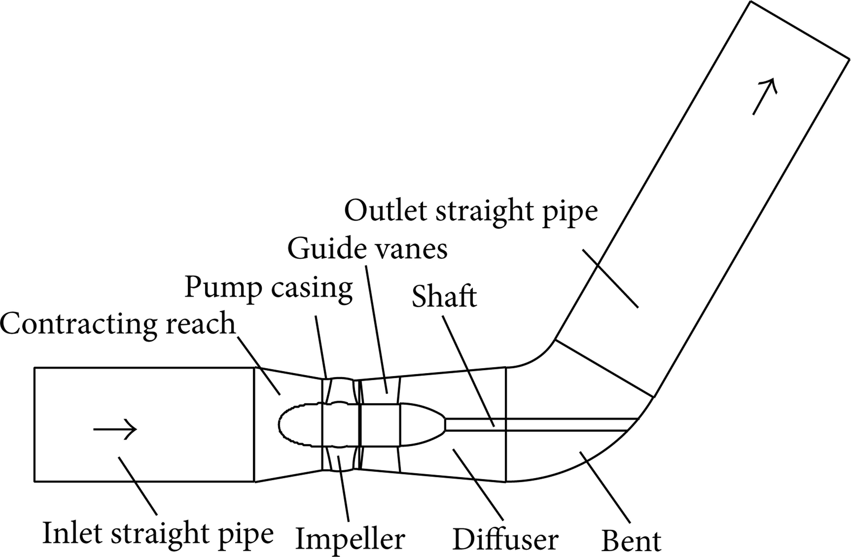
Figure 1 is a structural sketch of a tubular pump with adjustable guide vanes.

Tubular pump with adjustable guide vanes.
The controller ring will rotate under the push of power relay mechanism, which will force the crank web and connecting rod to move, and finally drive adjustable guide vanes to rotate around their own axis; thus the inlet setting angle of guide vanes can be adjusted according to the requirements of the pump operation conditions to match the outlet flow angle of impeller blades.
3. Numerical Computation Models
3.1. Computation Domain
The geometrical model of tubular pump for numerical computation is shown in Figure 2. The diameter of impeller is 300 mm, possessing 3 adjustable blades, and the rotational speed is 1450 rpm. The diffuser has 5 adjustable guide vanes that their inlet setting angles can be adjusted around their axis line in contrasting computing cases. The diameter of bent is 350 mm. Straight guide vanes are adopted in the building of three-dimensional models. For a specific guide vane, the value of the inlet setting angle will be kept the same in different radii, no matter the cross section is close to the hub or near the pump casing.
Computation domain.
3.2. Mathematics Models
3.2.1. Governing Equations
During normal operation of a tubular pump, the internal flow velocity is relatively low and the change of water density can be neglected. Therefore, the 3D time-averaged N-S equations can be used to describe the internal steady and incompressible flow fields as described in [10–12]. The mass conservation equation and momentum equation can be written as

3.2.2. Turbulence Model
The standard κ-ε turbulence model is adopted to close the N-S equations, as discussed [13–15]. Consider
in which p r is turbulent energy productivity which can expressed as

and p denotes total pressure equaling static pressure plus centrifugal force; x i and u i (i = 1, 2, 3) stand for coordinate and velocity component, respectively; coefficients and constants are defined as μ t = (cμ ρ)(k2/ε), cμ = 0.09, c1 = 1.44, c2 = 1.92, σ k = 1.00, and σε = 1.30.
3.2.3. Boundary Conditions
By using commercial software of Gambit and Pro/E, three-dimensional tubular pump models for numerical computation are generated. Boundary conditions are set as [16, 17].
The inlet of the computed domain is the inlet section of the inlet straight pipe, and the boundary condition is treated as velocity inlet. According to the Reynolds number and wet circumference of the inlet flow the inlet turbulent intensity and hydraulic diameter are determined.
The outlet of the computed domain is set in the outlet section of the outlet straight pipe, and the boundary condition is given as outflow, assuming that the flow in the outlet section takes the form as single direction and the gradients of all flow parameters are equal to zero.
All walls including surfaces of pump casing, blades, and guide vanes in the computed domain are fixed walls satisfying no-slip conditions, and velocities, pressure, and other flow parameters in the near wall region are calculated by means of wall functions.
3.2.4. Grid Generation, Discretization, and Solution
The commercial CFD software Fluent is adopted to simulate the internal flow of tubular pumps with fixed guide vanes and adjustable guide vanes. Mixed meshes of unstructured four-face body meshes and structured six-face body meshes, about 480,000 computing nodes, are generated to accommodate the complex structure of computed models. The discretization of governing equations is done by finite volume method. The multireference frame is applied to treat the interference between the rotational impeller and the static diffuser; see [5, 18]. The algorithm SIMPLEC is adopted to couple the calculation of velocity and pressure to improve computation efficiency and accelerate convergence.
The checking of mesh quality and the work of independence solution of mesh size were completed before formal numerical computations are commenced. The computation domain was meshed with different sizes. The grids number was finally selected by comparing the difference of the computed pumping efficiency of the pump with fixed guide vanes at the designed flow rate with that of the model test result. The difference of pumping efficiency tended to become smaller with the increase of grids number, and when the relative error of the two pumping efficiencies was smaller than 0.20% the corresponding meshed grids were considered satisfactory to conduct the follow-up computations.
4. Results and Discussion
4.1. Internal Flow Analysis of Fixed Guide Vanes
Based on the numerical simulation results, corresponding to different inlet setting angles of impeller blades and guide vanes and different characteristic flow rates, such as at the designed flow rate, a smaller flow rate, and a larger flow rate, the internal flow fields of tubular pump with fixed guide vanes can be analyzed, focusing on the comparison of internal flow of diffusers with fixed and adjustable guide vanes. In this subsection the inlet setting angles of impeller blades and fixed guide vanes are all set at 0 degree.
4.1.1. Internal Flow of Fixed Guide Vanes at Q = Q0
Figure 3 shows the internal flow profiles of a fixed guide vane at the designed flow rate in a smaller radius near the hub and a larger radius near the wall of pump casing. From Figure 3 it can be seen that at designed flow rate the flowing around the guide vanes is smooth without obvious flow separation and vortex, and the inlet flow is basically along the direction of guide vane chord. The inlet setting angle of guide vanes is equal to the outlet flow angle of water from the impeller; no impact loss happened.

Internal flow profiles of fixed guide vane at Q = Q0.
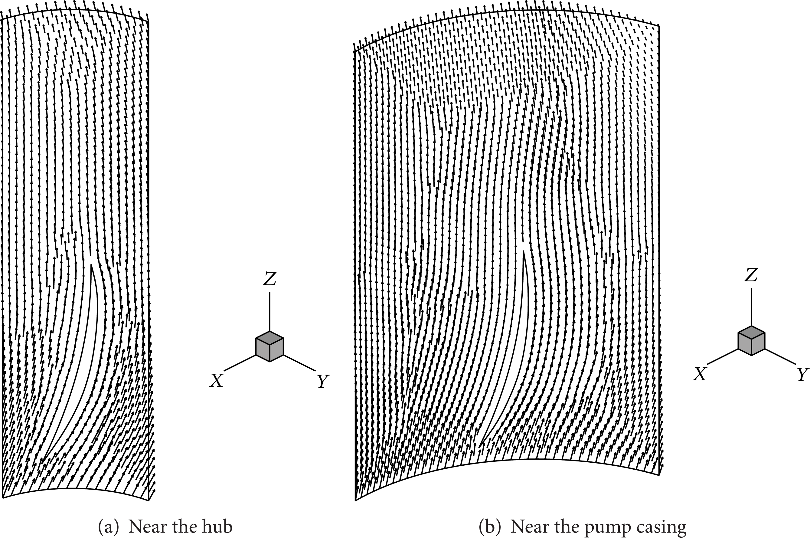
4.1.2. Internal Flow of Fixed Guide Vanes When Q < Q0
With the decrease of flow rate the outlet flow angle of water from the impeller becomes smaller automatically. However, since the fixed guide vanes cannot be adjusted to accommodate such a change, the incoming water from the impeller enters the diffuser at an attack angle smaller than the setting angle of the guide vanes, resulting in flow separation and vortex. From Figure 4(a) the large range of vortex at the back of fixed guide vane can be easily seen. Comparing Figures 4(a) and 4(b), it is found that the more approaching the hub, the stronger the vortex. Since the tubular pump is running at small flow rate (Q = 0.75Q0), the pumping heads are imbalanced in the different radii of impeller and the “secondary flows” may have been generated inside the impeller.

Internal flow profiles of fixed guide vanes at Q = 0.75Q0.
4.1.3. Internal Flow Analysis of Fixed Guide Vanes at Larger Flow Rate
From the knowledge of velocity triangle of pump we know that with the increase of flow rate the outlet flow angle of water from the impeller becomes larger and larger. Figure 5 shows the internal flow profiles of fixed guide vanes at 1.14 times designed flow rate, indicating that the inflow of water entering the diffuser does not fully run along the outer boundary of guide vanes any more.

Internal flow profiles of fixed guide vanes at Q = 1.14Q0.
There is an included angle between the direction of velocity vector and the inlet setting angle of guide vanes, and the attack angle of incoming flow is greater than the inlet setting angle. The flow separation begins appearing at the head of guide vanes. The more approaching the pump casing is, the more serious the phenomenon becomes. The flow field becomes unsteady, and the low speed zone can be easily seen on the left side of the guide vane in Figure 5(b). Moreover, comparing with Figures 5(a) and 5(b) the velocity difference between the smaller radius zone and the larger radius zone becomes more obvious when the tubular pump runs under off-design condition when the flow rate is larger than the designed one. The more nearing the pump casing, the larger the value of velocity, indicating that the flow pattern from the impeller itself is not uniform.
4.2. Internal Flow Analysis of Adjustable Guide Vanes
The design of adjustable guide vanes can improve the internal flow fields of diffuser by adjusting the inlet setting angles of guide vanes to accommodate off-design flow rates and incoming flow angles. In this subsection the inlet setting angle of impeller blades is fixed at 0 degrees for the next two illustrating cases, and the inlet setting angles of adjustable guide vanes can be adjusted according to the operation conditions.
4.2.1. Internal Flow of Adjustable Guide Vanes When Q < Q0
Figure 6 illustrates the internal flow profiles of an adjustable guide vane at smaller flow rate, Q = 0.75Q0; all computation conditions are kept the same as shown in Figure 4 except that the inlet setting angle of guide vanes is adjusted to be smaller from 0 degrees to minus 2 degrees. In comparison of Figure 6(a) with Figure 4(a), it can be seen that the difference between the outlet flow angles of water from the impeller and the setting angles of guide vanes becomes smaller, and the flow patterns are improved in a certain degree, but there still are vortexes and flow separation near the hub zone of the diffuser. However, it is found surprising, after comparing Figure 6(b) with Figure 4(b), that the effect of flow pattern improvement is pretty satisfying in the zone near the pump casing of the diffuser by adjusting the setting angles of guide vanes to be smaller by 2 degrees. This phenomenon reflects a defect, in the selection of adjustable guide vanes used in the computation model, that straight guide vanes should be avoided, and twist guide vanes may be the first choice and optimal hydraulic design of guide vanes should be carried out.

Internal flow profiles of adjustable guide vanes at Q = 0.75Q0.
4.2.2. Internal Flow of Adjustable Guide Vanes When Q > Q0
From the internal flow analysis of fixed guide vanes we know that when a tubular pump is running at a flow rate greater than the designed flow rate, the inlet setting angles of guide vanes should be adjusted to be larger to adapt the change of inflow fields from the outlet of impeller.
Figure 7 shows the internal flow profiles of an adjustable guide vane; all computation conditions are kept the same as in Figure 5 except that the inlet setting angle of guide vanes is adjusted to be larger from 0 degrees to plus 2 degrees. From Figure 7 it can be seen that flow pattern in both sides of the guide vane is improved, and the low velocity zone obviously lessened.
Internal flow profiles of adjustable guide vanes at Q = 1.14Q0.
4.3. Hydraulic Loss in Diffusers
In the process of flowing round the guide vanes from the inlet cross section to the outlet cross section of the diffuser, energy and hydraulic loss will inevitably happen. Computed results indicate that when the setting angle of blades is fixed and the inlet setting angle of guide vanes can be adjusted, then the hydraulic loss in diffuser will be directly related to the inlet setting angles of guide vanes and flow rates. The hydraulic losses vary with the flow rate and the curves are concave ones (see Figure 8). Beginning with smaller flow rate, with the increase of flow rate, the hydraulic loss decreases gradually until it reaches the lowest point, corresponding to the best efficiency point of the pump, and then tends to increase afterwards.
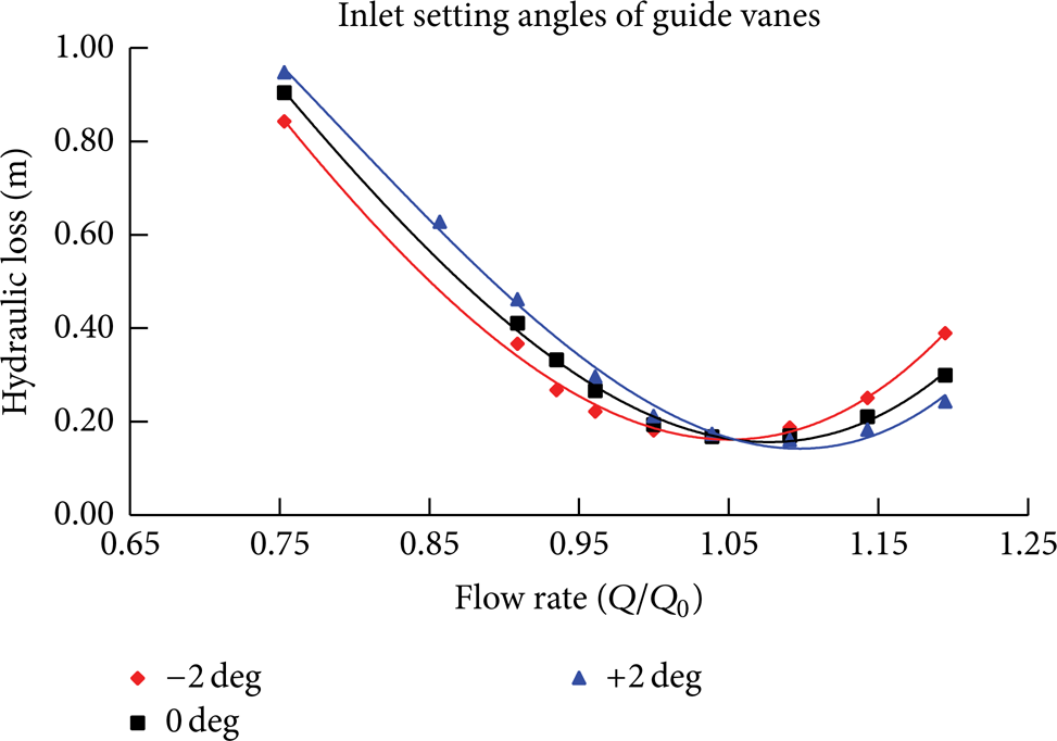
Hydraulic loss in diffusers.
The influence of inlet setting angles of guide vanes on the hydraulic loss of diffusers is obvious. When the tubular pump is running at smaller flow rate and employing smaller inlet setting angle of guide vanes the hydraulic loss of the diffuser can be effectively reduced, revealing the advantages of adjustable guide vanes from another aspect. On the contrary, when the tubular pump is running at larger flow rate the inlet setting angle of guide vanes should be adjusted to be larger in order to reduce the hydraulic loss of the diffuser. Hence, the design of adjustable guide vanes can help reduce hydraulic loss of diffuser under off-design conditions.
4.4. Performance Prediction of Tubular Pump with Adjustable Guide Vanes
Based on the comparative numerical computations of tubular pumps with fixed guide vanes and adjustable guide vanes, with respect to different flow rate, the pumping head can be calculated by the total pressure difference between the inlet section of contracting reach and the outlet section of bent pipe, and the waterpower can be determined by the rotational speed and the water momentum acting on the impeller. Finally, the hydraulic efficiency of pump can be worked out on the basis of flow rate, pumping head, and waterpower, as shown in [19, 20]. Figure 9 gives the characteristic curves of a tubular pump with adjustable guide vanes when the blade angle is fixed at 0 degrees.

Characteristic curves of a tubular pump with adjustable guide vanes.
From Figure 9 it can be seen that when the setting angle of blades is fixed at 0 degrees, the energy performances of tubular pump will vary with the setting angle of adjustable guide vanes. When the setting angle of guide vanes is adjusted to be larger or smaller by 2 degrees, relative to 0 degrees, the difference of highest efficiencies corresponding to the three different setting angles of guide vanes is about 0.51%. The smaller the setting angles of guide vanes, the greater the pumping heads curves’ slope, and the higher the highest hydraulic efficiency at designed flow head. The difference in pumping heads at different setting angles of guide vanes, with respect to the designed pumping head, is not obvious, meaning that at designed flow rate the influence of adjusting the setting angles of guide vanes in a certain range upon the pumping head and highest efficiency of tubular pump is slight.
Adjusting the inlet setting angles of guide vanes, however, can have great effect on the hydraulic efficiency improvement of tubular pumps under off-design conditions. For example, the hydraulic efficiency of tubular pump with fixed guide vanes at 0.75Q0 is 68.50%, which can be raised to 70.20% by adopting adjustable guide vanes and adjusting their setting angles from 0 degrees to minus 2 degrees. When the tubular pump runs at 1.20Q0, the pumping efficiency of tubular pump can be raised from 67.67% to 69.86% if the setting angle of guide vanes is adjusted from 0 degrees to plus 2 degrees. The improvements of tubular pump efficiency with adjustable guide vanes at off-design flow rates are considerable, which cannot be easily achieved by optimal design of impeller and diffuser since in the past 20 years the mean highest pump efficiency is only raised by about 3%; see [21, 22], and further improvement becomes more and more difficult.
4.5. Verification of Numerical Computation Validity
The validity of numerical computation results was verified by comparing the computed tubular pump performances with the model test results. The model pump used in the computation was one of the pump models tested in the same test stand for South-to-North Water Diversion Project (see [22]), so that the test results can be quoted to verify the computation validity and reliability of the paper. Figure 10 shows the comparison of computed pumping head and efficiency with those obtained by model test of the same pump with fixed guide vanes. The setup in the numerical simulation and model test is the same, including the same inlet setting angle of impeller blades and the same rotating speed as well, from which it was seen that the pump performance predicted by numerical method was in substantial agreement with the model test results. Thus the computed results on the tubular pump with adjustable guide vanes were reliable and believable.

Comparison of computed pump performances with model test results.
5. Conclusions
On the basis of analysis of defects of fixed guide vanes, the proposal of tubular pump with adjustable guide vanes is put forward. The inlet setting angles of guide vanes can be adjusted to adapt the operating conditions of pump at off-design flow rates, match the outlet flow angle of impeller, and improve internal flow fields of diffuser and achieve higher pumping efficiency.
Numerical simulation and comparison results indicate that the flow conditions inside the diffuser of tubular pumps with adjustable guide vanes can be obviously improved and when operating under off-design conditions the hydraulic loss of diffuser can be effectively reduced.
When the setting angle of blades is fixed the performance of a tubular pump will vary with the setting angles of guide vanes and flow rates. The values of the highest hydraulic efficiency are slightly changed when the setting angles of guide vanes are adjusted within a certain range. Higher pumping efficiency can be achieved for a tubular pump with adjustable guide vanes under off-design conditions.
The design scheme of adjustable guide vanes can be applied to tubular pumps and different structural axial-flow pumps with fixed, semiadjustable, and fully adjustable blades.
Conflict of Interests
The authors declare that there is no conflict of interests regarding the publication of this paper.
Footnotes
Acknowledgments
This paper is financially supported by the 11th Five Year Key Project of China's National Scientific Support Scheme (Grant no. 2006BAB04A03) and the open project from Jiangsu Province Key Lab of Hydraulic & Power Engineering (Grant no. K100016).