
Abstract
In the process of motor rotation, the vibration caused by the rotor mass eccentricity seriously affects the dynamic characteristics and safety operation of system. So rotor mass eccentricity vibration compensation control on rotating machine has great significance, especially for the high speed bearing less induction motor (BIM). A rotor mass eccentricity compensation control strategy was presented to restrain the vibration of suspended rotor for BIM. Firstly, the suspension rotor dynamical model was deduced and unbalanced vibration mechanism was analyzed. Secondly, based on decoupling control between electromagnetic torque and radial force, the obtained vibration signal from the displacement sensor was put into the original radial force control system. Then, a feedforward compensator was set up to increase the same period component of the given radial force signal and enlarge the stiffness of the vibration signal. Finally, the compensation control of rotor vibration was realized by forcing the rotor shaft rotation around its geometric center. The simulation results show that the presented feedforward compensator can suppress the vibration of rotor under different speed and improve the precision of rotor suspension. The further experimental results also show that the control method can obviously reduce the peak-peak value of rotor radial displacement and effectively restrain rotor vibration.
1. Introduction
Bearingless induction motor (BIM), with the advantages of simple structure, low cost, uniform air-gap, high reliability, low cogging torque ripple, wide range of weak magnetic, and so forth, can use ordinary squirrel cage rotor with high mechanical strength. This makes it have broad application prospects including turbines molecular pump, compressor, high speed electric spindle, and aerospace and fly wheel energy storage [1–4]. However, BIM has the problem of rotor mass eccentricity caused by some machinery imbalance in practical engineering applications, such as the uneven distribution of rotor lamination quality and the processing and assembling accuracy. An excitation force with the same frequency of speed will be produced on the rotor, which can result in the radial vibration of the rotor when the speed reaches a certain degree. The vibration not only reduces the rotation precision of the rotor and affects the dynamic performance of the system, but also increases the motor noise when a part of vibration force is transmitted to the frame through the air-gap. In addition, the excitation force is proportional to the square of speed [5], so it will increase rapidly when BIM is at high speed. The performance and safe operation of the system will be seriously affected. Therefore, it is of great theoretical and realistic significance to study the mass eccentricity of high speed rotor. Many compensation methods have been put forward by domestic and foreign scholars [6–10]. These methods can be divided into two categories: the first one is to eliminate the unbalanced force called unbalanced displacement compensation (force minimum criterion); the second one is to eliminate the displacement called unbalanced force compensation (displacement minimum criterion). In short, the former makes the rotor rotate around its inertial axis by reducing the stiffness and damping of the suspension rotor at a certain speed, while the latter makes the rotor rotate around its geometric center axis by increasing the stiffness and damping of the suspension rotor.
For the bearingless motor with high speed rotating ability, suspension rotor vibration suppression is a hot issue in many scholars research and has achieved some research results [11–14]. In [11], taking the rotor eccentricity into consideration, a radial levitation force closed loop control strategy was introduced to reduce the peak to peak value of the vibration displacement. As a result, the static and dynamic performance was improved for the suspension rotor; however, this method should obtain the accurate analytical model of radial levitation force. In [12], an unbalanced compensation control system was designed based on feedforward method for rotor vibration compensation control in bearingless permanent magnet synchronous motor, which reduced the vibration amplitude of rotor and improved the rotation precision of rotor greatly and achieved satisfactory results, but the research was only in the low speed. In [13], a feedback compensation controller was designed based on the intrinsic characteristics of the unbalanced disturbance force, and the vibration was effectively attenuated in bearingless permanent magnetic slice motor, but the method needed a large number of mathematical calculations. In [14], an adaptive notch filter was designed based on the least mean square (least mean square, LMS) algorithm to compensate the same frequency vibration displacement of the rotor and suppress the rotor eccentricity vibration in bearingless switched reluctance motor at different speed conditions; then the precision of rotor suspension was improved, but the step factor, which decided the stability and convergence rate of the adaptive filter, was difficult to determine.
In this paper, on the basis of feedforward method, an unbalanced compensator was put forward to solve the vibration problem caused by the mass eccentricity of high speed suspension rotor for BIM. Firstly, the vibration signal was extracted from the detected displacement signal. Then, it was added to the original radial levitation force control system, so as to carry out the feedforward compensation control for the unbalanced excitation force and achieve the goal of reducing rotor vibration. On the basis of decoupling control between torque and radial levitation force, a BIM simulation control system was constructed in Matlab/Simulink toolbox. The simulation research was carried out in the low speed and high speed. To further verify the validity and the correctness of the proposed control strategy, the vibration suppression was studied on the BIM digital control system experimental platform. The simulation and experimental results all indicate that the proposed compensation control strategy can effectively restrain the rotor vibration and improve the precision of suspension rotor. The system has good compensation control effects in a wide speed range, especially for the high speed.
2. The Dynamics Model of BIM Suspension Rotor
Embedding other windings called radial levitation force windings in the stator of ordinary induction motor, a BIM is formed. The pole pairs of the torque winding and radial levitation force winding are P1 and P2, respectively; the electrical angular frequencies are ω1 and ω2, respectively. When the pole pairs between the two sets of windings are P2 = P1 ± 1 and the electric angular frequency between the two sets of windings is ω1 = ω2, the motor rotor can simultaneously realize the function of levitation and rotation [3]. In this paper, the vibration problem caused by the mass eccentricity was researched for the high speed suspension rotor of BIM. The trajectory of the rotor must be analyzed before the rotor vibration compensation [8, 9]. When the rotor rotates with an angular velocity ω, the rotor mass eccentricity, if present, will cause the inertia axis c and the geometric axis m noncoincidence. The suspended rotor eccentricity coordinate is shown in Figure 1. Under the rectangular coordinate system, the rotor centroid coordinates can be expressed as
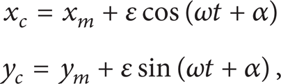
where ∊ is the eccentric distance of rotor inertia axis relative to the geometric central axis; ω is the rotor speed; α is the initial phase angle; x c (y c ) is the rotor inertia center (centroid) coordinates; x m (y m ) is the motion coordinates for rotor geometric center.

Suspended rotor eccentricity coordinate.
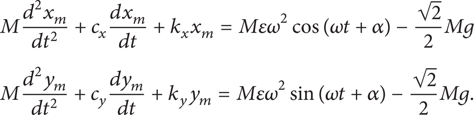
In order to facilitate the analysis, ignoring the cyclotron effect, the motion equations of the rotor can be established by Newton's laws:

where M is the rotor quality; c x and c y are the coupling parameter; k x and k y are the stiffness coefficient; the right of the equality is the static gravity.
Considering the rotor mass eccentricity, the right of formula (2) should be combined with the centrifugal force. Then formula (2) turns into
Solving (3), the rotor suspension steady-state response can be obtained as follows:

where

where ∊ x (∊ y ) is component in the x(y) axis of the eccentric distance:

From formula (4), it can be seen that the movement track of the rotor geometric center is an ellipse under the effects of the centrifugal force generated by rotor mass eccentricity; if there is the same stiffness in x and y direction of the suspension rotor, the rotor trajectory is a circle. If the rotor shaft rotates around its geometry, the obtained offset signal from displacement sensor detection is zero. But if the rotor mass imbalance exists, the rotor will be deviated from the geometric central axis under the centrifugal force; thus the achieved displacement signal from displacement sensor detection will include rotor vibration signal. Because the amplitude of the vibration signal is proportional to the square of the speed, there will be a part of the vibration force to the engine base when the motor is in high speed or ultrahigh speed operation. As a result, the motor noise will be increased and the performance and safe will be impacted for the high speed rotor system. In this paper, on the basis of the principle of rotor displacement signal, a compensation force contrary to unbalanced force is exerted to the rotor to compensate the mass unbalance. The rotor vibration suppression is realized by forcing the rotor shaft to rotate around the geometric center.
3. The Design of Feedforward Compensator
The rotor vibration feedforward compensator is designed for the BIM on the basis of the air-gap magnetic field oriented decoupling control [15]. Analyzing the rotor trajectory, it can be found that the displacement signal from sensors not only contains the vibration signal with the same frequency of the speed but also contains some other interference signals. The vibration signal obtained from the displacement signal is put into the radial levitation force control system. A feedforward compensator is set up to increase the control force of the same period component for the given output signal F x * and F y *, so as to increase the stiffness of the vibration signal for the radial control system and force the rotor shaft rotation around the geometry central axis. The unbalanced compensation control system block diagram is shown in Figure 2.

Block diagram of the rotor unbalanced compensation control system for bearingless induction motor.
3.1. Extraction of the Vibration Signal
Extracting the vibration signal with the same frequency of the speed from the displacement signal is a precondition to realize the rotor vibration feedforward compensation control. The vibration signal was obtained by rotation coordinate transformation in this paper. The achieved geometry center displacement signals X s and Y s from displacement sensor detection were transformed from the rectangular coordinate to the rotation coordinate transformation. In the displacement signal, the vibration signal with the same frequency of the speed was converted into DC signal, and the interference signal with different frequency of the speed was converted into a double frequency signal. The sum of the two is Xr1 and Yr1, respectively:

Using a low pass filter, those signals were transformed to the only DC component signals Xr2 and Yr2. At last, the DC component was carried out in the coordinate inverse transformation, and the extraction of the vibration signal was realized:

At this time, the vibration signals are the compensation signals X c and Y c . The signal X c (Y c ) is a sinusoidal function with the same frequency and phase of the F zx (F zy ). The rotor mass unbalanced compensation can be achieved by changing the compensation signal amplitude which is gotten by adjusting proportional coefficient k of the compensation controller. The whole process can be shown in Figure 3, where the “T” represents the rotation coordinate transformation matrix; the “C” represents the low pass filter; the “T−1” represents the coordinates inverse transformation matrix.

Coordinate transformation and vibration signal extraction.
3.2. Calculation of the Centrifugal Force
Because of the centrifugal force, the rotor rotation deviates from the geometric central axis to make the vibration. So constructing the simulation system must take the effect of centrifugal force into account. In this paper, the static unbalance caused by the rotor inertia axis and the geometric central axis misalignment is considered, while the dynamic imbalance caused by the inertia axis and the geometric central axis with a certain angle is not considered. Assuming the eccentricity is ∊, the motor displacement has the same stiffness in the x and y direction. The real-time rotor angular velocity ω, which can be calculated by centrifugal force module, is regarded as the input signal for the compensation controller, so that the centrifugal force calculation is adaptive. When the rotor rotates with the speed ω (rad/s), the expression of the centrifugal force acting on the rotor can be written as

From the equation above, it can be found that the centrifugal force is proportional to the square of the speed. With the increasing of the speed, the centrifugal force will increase rapidly, even when there is a very small eccentricity. So the necessity of rotor eccentricity compensation is reflected in the other side.
4. Simulation and Experiment Research
4.1. Results and Analysis of the Simulation
To verify the effectiveness of the proposed rotor vibration compensation control strategy for BIM based on the feedforward method, a simulation model control system was constructed by using the Matlab/Simulink toolbox. The simulation system of the feedforward compensation controller is shown in Figure 4, which includes the extraction of the vibration signal and the centrifugal force calculation. In the simulation, the algorithm was set as variable step size Ode23t, the starting time was 0 s, and the termination time was 0.3 s. The parameters of the BIM are shown as follows: the rotor mass m = 2.85 kg; the rotational inertia J = 0.00769 kg·m2; the eccentricity ∊ = 0.3 mm; the torque winding: the pole pairs P1 = 1; the stator resistance is 2.01 Ω. The mutual inductance of stator and rotor is 0.15856 H. The stator leakage inductance is 0.00454 H; the suspension winding: the pole pairs P2 = 2; the stator resistance is 1.03 Ω. The rotor resistance is 0.075 Ω. The mutual inductance of stator and rotor is 0.00932 H. The stator leakage inductance is 0.00267 H. The rotor leakage inductance is 0.00542 H. The simulation results under the two different typical types of speed are shown in Figures 5–7.

The simulation model of feedforward compensator.

The vibration suppression simulation results at the speed of 2000 r/min.

The vibration suppression simulation results at the speed of 9000 r/min.

The trajectories of rotor geometry center when stable suspension at the speed of 9000 r/min.
The low speed (2000 r/min) simulation results are shown in Figure 5 for the rotor vibration of BIM. The suspension rotor geometric center m in x and y direction displacement waveforms without a compensation controller is shown in Figures 5(a) and 5(b). The suspension rotor vibration peak to peak value is about 24 µm in the steady-state; by contrast, the suspension rotor geometry center m in x and y direction displacement waveforms with a compensation controller is shown in Figures 5(c) and 5(d). The peak to peak value is about 8 µm in the steady-state. From Figure 5, it can be seen that the vibration amplitude of the rotor is reduced with a feedforward compensator and the effectiveness of the designed controller is proved.
The high speed (9000 r/min) simulation results are shown in Figures 6 and 7 for the rotor vibration of BIM. The suspension rotor geometric center m in x and y direction displacement waveforms without a compensation controller is shown in Figures 6(a) and 6(b). The motor rotor vibration peak to peak value is about 48 µm in the steady-state; by contrast, the suspension rotor geometry center m in x and y direction displacement waveforms with a feedforward compensator is shown in Figures 6(c) and 6(d). The peak to peak value is about 12 µm in the steady-state. From Figure 6, it can be found that, after using the designed feedforward compensator, the vibration caused by the suspension rotor mass imbalance can be suppressed effectively and the rotation precision of rotor can be improved greatly.
The rotor displacement trajectory waveforms without and with a feedforward compensator are shown in Figures 7(a) and 7(b), respectively. In Figure 7, due to the assumption of the BIM with the same stiffness in x and y direction, it can be seen that the trajectory of rotor geometry center is a circle when stable suspension is at the speed of 9000 r/min. The effectiveness of the proposed control strategy is testified more clearly. Comparing the simulation results of Figures 5 and 6, it also can be found that there is a satisfactory suppression effect of vibration compensation for BIM in low and high speed. The rotor vibration peak to peak value is about 1/3 of that before without compensation control in low speed, while the rotor vibration peak to peak value is about 1/4 in the state of high speed. That shows the proposed method can compensate the rotor vibration in a wide speed range, especially significant effect at high speed.
4.2. Results and Analysis of the Experiment
In order to further prove the correctness and effectiveness of the proposed suppression method, with a two-degree-of-freedom BIM as the experimental object, the digital control experimental platform was constructed using the DSP TMS320F28335 as the core. The self-made prototype parameters are the same as simulation parameter. The given speed of experimental machine is set at 2000 r/min. The experimental results are shown in Figure 8.

Experimental results.
Figure 8(a) shows the radial displacement in the x direction without a feedforward compensator. It can be seen that the peak to peak value of vibration displacement is within 50 µm and the vibration range is far less than the length of motor air-gap. The motor realizes stable suspension; Figure 8(b) shows the radial displacement in the x direction with a feedforward compensator. It can be seen that the peak to peak value of vibration displacement is within 25 µm. The vibration amplitude is reduced to half of the original using feedforward compensator. So the inhibitory effect is obvious and the system control precision is improved. Those show that the BIM achieve stable suspension and the correctness and effectiveness of the proposed control method are verified.
5. Conclusions
In this paper, the unbalanced vibration mechanism was analyzed on the basis of deducing the dynamic model of suspension rotor for the BIM. The rotor mass unbalanced compensation of BIM was achieved based on the feedforward compensation algorithm. According to the theoretical analysis and the simulation study and the experimental test, the following conclusions can be drawn.
This method can compute the rotor speed in real-time, which makes the calculation of the centrifugal force with the adaptability and the rotor mass unbalanced compensation in real-time.
The proposed compensation control method can reduce the rotor vibration peak to peak value and improve the precision of the suspension rotor. The validity of the feedforward compensation controller is proved for the rotor vibration suppression.
Different speed simulation results and experimental results show that the proposed method can compensate rotor vibration in a wide speed range.
Conflict of Interests
The authors declare that there is no conflict of interests regarding the publication of this paper.
Footnotes
Acknowledgments
This work was supported by the National Natural Science Foundation of China under Project nos. 51305170, 51475214, and 61104016, the China Postdoctoral Science Foundation funded project under Project nos. 2014T70482, 2012M521012, and 2014M561583, the Natural Science Foundation of Jiangsu Province of China under Project nos. BK20130515 and BK20141301, the Professional Research Foundation for Advanced Talents of Jiangsu University under Project nos. 12JDG057 and 14JDG076, and six categories talent peak of Jiangsu Province under Project ZBZZ-017, and the Priority Academic Program Development of Jiangsu Higher Education Institutions.