
Abstract
Inherent characteristics of electrochemical drilling (ECD) mean that it is a major solution to the machining of deep small holes in difficult-to-cut materials. The removal of insoluble by-products from the machining gap determines the accuracy of control and limits process capacity. Pulsating electrolyte flow is introduced to enhance the removal rate of insoluble products by reducing the hold-down pressure caused by the electrolyte. Experiments are conducted to optimize a stimulus signal for the pulsation and to investigate the electrolyte pulsation frequency, pulsation amplitude, applied voltage, and electrode feed rate in the machining of deep small holes. The results indicate that optimized pulsating flow is effective in accelerating by-product removal and enhancing machining accuracy and maximum machining depth. With the optimized parameters of 5 Hz in frequency, 0.2 MPa in amplitude, and 0.5 MPa in average pressure, a deep hole was machined in titanium alloys of 20 mm depth and 1.97 mm averaged diameter.
1. Introduction
Deep small holes with considerable aspect ratios, such as cooling holes in turbine blades and vanes, have been widely applied in the aerospace field [1, 2]. These holes are typically made of nickel-based super alloys, titanium alloys, and intermetallic compounds, which are difficult-to-work-with mechanical machining technologies. Nontraditional machining technologies are mostly used, regardless of the mechanical properties of the materials. Laser drilling and electric discharge machining (EDM) produce recast layers on the surface, which must be subsequently removed in applications demanding a specific surface finish. Additionally, with the increase of machining depth, tool wear in EDM worsens and the machining efficiency reduces. Electrochemical drilling (ECD) can achieve high surface quality with an absence of tool wear and metallurgical defects. The inherent characteristics of ECD mean that it can be a major solution for machining deep small holes in difficult-to-cut materials [3, 4].
In industrial applications, acid solutions are developed to avoid the formation of insoluble hydroxides from dissolved metal ions. However, the environmental treatment of acid effluent is expensive. Therefore, many efforts have been made to replace acid solutions with neutral salt solutions [5–7]. In neutral aqueous solutions, the electrolytic products typically cohere into a flocculent structure in deep hole drilling. Delayed sludge removal may block the electrolyte passage, bridge the connection between the electrodes, and induce short circuits. By-product removal in ECD with neutral salt solutions therefore determines the accuracy of control and limits the process capacity. Various approaches have also been proposed to accelerate the electrolytic refreshment.
Skoczypiec [8] found that electrode ultrasonic vibrations change the conditions of electrochemical dissolution. The electrolyte flow, as well as electrode polarization, was enhanced by turbulent cavitations. Rajurkar and Zhu [9] applied an orbital motion to the tool cathode, which periodically expanded the side machining gap and made by-product removal easier. Hewidy [10] found that low-frequency vibrations of the tool cathode changed the physical condition in the frontal machining gap and extruded the electrolyte. Guo [11] invented a coaxial method by pumping in fresh electrolyte and extracting by-products at the hole entrance to restrict the submerged region and reduce the waste removal. Li et al. [12] progressively increased the electrolyte pressure in deep hole drilling to maintain a necessary electrolyte velocity for by-product removal. However, this issue has not been satisfactorily solved.
Pulsating flow, which creates periodic fluctuations of fluid flow and alters the thickness of the boundary layer, has been verified as effective in multiphase flow [13, 14]. However, there are limited studies on pulsating flow in electrochemical drilling. This work focuses on the improvement of by-product removal in deep hole drilling with pulsating electrolyte flow. Experiments are also carried out to study the effects of pulsation parameters on by-product removal rate, hole performance, and maximum machining depth in drilling of titanium alloys.
2. Principles of ECD with Pulsating Electrolyte Flow
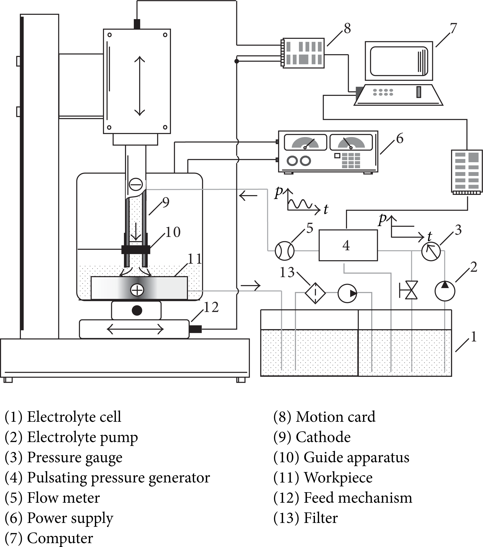
Figure 1 shows a schematic diagram of ECD with pulsating electrolyte flow. Different from the typical ECD process with a constant flow, pulsating flow is an unsteady flow characterized by periodic fluctuation of the mass flow rate and pressure. Typical stimulus signals for pressure pulsation are presented in Figure 2. T and A denote the pulsation period and amplitude, respectively, and pav is the averaged electrolyte pressure over the pulsation period.

Schematic diagram of ECD with pulsating flow.

Typical stimulus signals for pressure pulsating.
In ECD with pulsating electrolyte flow, the workpiece is electrically connected to the positive pole of a pulse power supply and the tube tool is connected to the negative pole. The pulsating electrolyte with a velocity of 10–30 m/s is pumped into the interelectrode gap from the hollow center of the tube tool. When the tool electrode is fed at a constant rate into the workpiece, the material is dissolved, forming the desired hole.
The perturbation and turbulence of pulsating flow intensely agitate the electrolyte mixed with insoluble sludge and bubbles. Agitation makes the products disperse more quickly and the distribution more uniform. When the pulsating flow is applied, a periodical low-pressure area is created in the machining gap, which reduces the hold-down pressure caused by the electrolyte on the by-products and enhances the refreshment of the electrolyte. As a result, process stability for deep hole drilling and hole quality can be enhanced.
3. System for ECD with Pulsating Electrolyte Flow
A specific system for drilling deep holes, equipped with pulsating electrolyte flow, is shown in Figure 3. This machining system consists of an electrochemical drilling machine, a pulsating pressure generator, an electrolyte circulatory system, a tool cathode guiding apparatus, and a power supply. The self-developed drilling machine can achieve precise feed in the X-Y-Z-axis.
Experimental set-up for ECD of deep holes with pulsating electrolyte flow.
In trial tests of this system, it is found that the tube electrode was forced to vibrate with the pulsating flow. In this case, the tube electrode acts like a cantilever beam and the vibration amplitude of the electrode tip was amplified with the increase of the pulsating frequency. The vibration generated by pulsating flow would be harmful to the machining. So, a guiding apparatus is designed to restrict the tool's vibration and enhance the hole profile cylindricity in the feeding direction.
The pulsating flow is generated by a servo-controlled module, which is connected in series in the electrolyte circulatory system. This servo system is composed of an energy accumulator, a servo valve, a controller chip, a filter, and a power unit, as shown in Figure 4. The core component of this module is a Get-type electrohydraulic servo valve (RT6615E, Radk-Tech, China), which can quickly respond to a broadband stimulus signal ranging from 0 to 100 Hz. The outflow of this valve varies with the position of the valve core, which is controlled by the stimulus signals. A real-time full feedback control system was established to set the stimulus signals and acquire the electrolyte pressure.

Servo system for pulsating pressure.
4. Experimental Results and Discussions
4.1. Selection of Stimulus Signals
Experiments were conducted to check the dynamic responses of the pulsating pressure servo system to typical stimulus signals, which are shown in Figure 2. Real-time electrolyte pressure at the outlet of the servo system was recorded and is presented in Figure 5. When the stimulus signals were at a frequency of 40 Hz, the electrolyte pressure consistently varied with the fluctuation of the signals. When sinusoidal and triangular waves were encouraged, the details of the original signals were maintained. However, distortions were observed when sawtooth waves and rectangular waves were driven. This servo system operates through mechanical actions of the servo valve core. Mechanical systems have inherent characteristics of coupling delay and filtering of high-frequency harmonics, which cause signal losses or jumping signals, such as sawtooth and rectangular waves. Hence, sinusoidal waves, which approximate to the fundamental wave, were selected to drive the pulsating electrolyte flow in the following experiments.
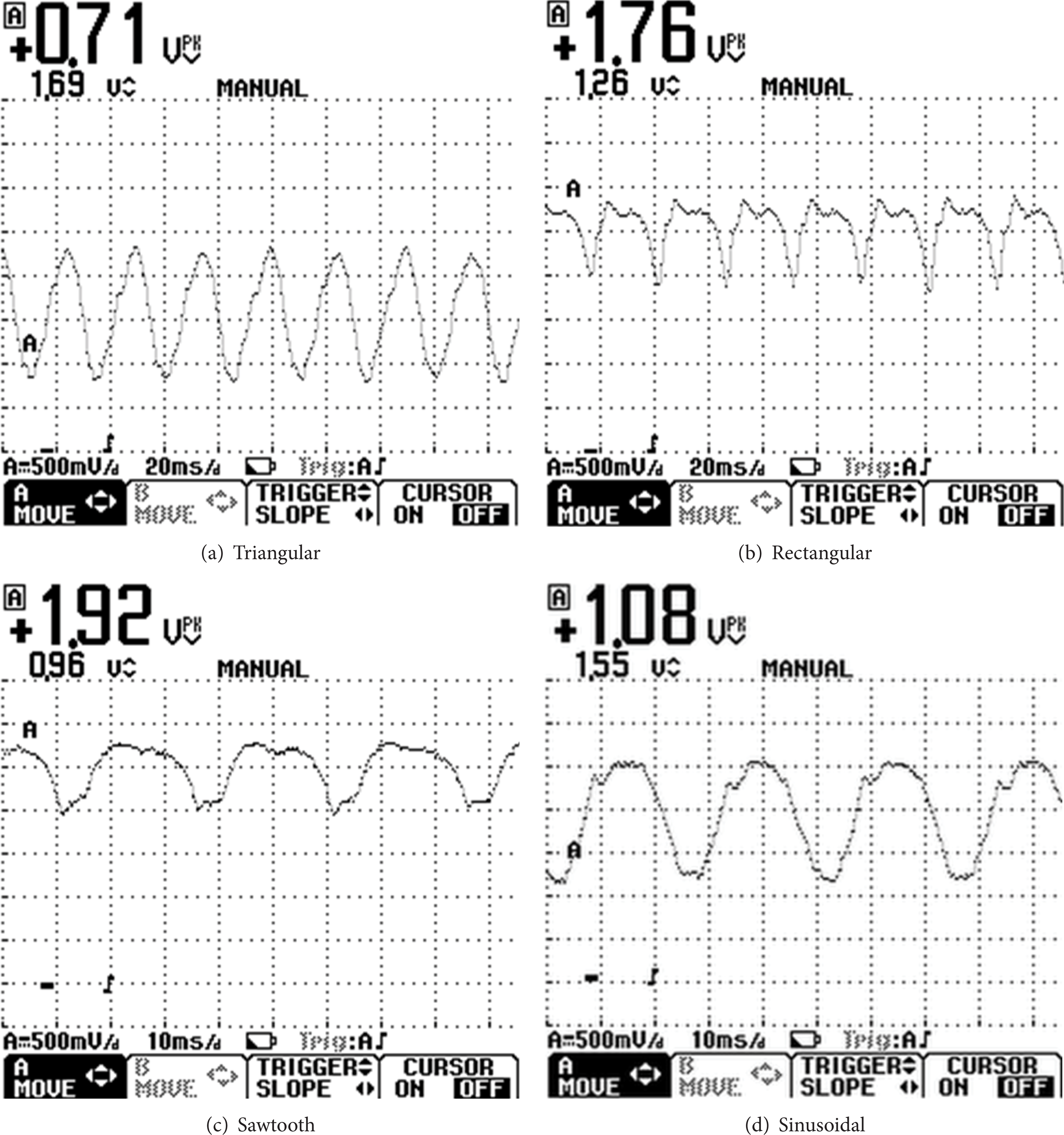
Pressure signals at outlet of the servo system.
4.2. Effects of Pulsating Flow on Product Removal
Samples of Ti6Al4V with a thickness of 20 mm were electrochemically drilled with different electrolyte flow conditions to study the effects of pulsating flow on by-product removal. In this experimental set, we applied a voltage of 26 V and an electrode feed rate of 0.6 mm/min. The other machining parameters are listed in Table 1.
Machining conditions.

Immediately after the experiments and before cleaning, the samples were observed using a 3D video microscope (DVM5000, Leica, Germany). The entrance characteristics of the deep drilled holes are presented in Figure 6. The hole shown in Figure 6(b) was machined with a constant electrolyte pressure of 0.4 MPa. Massive white electrolytic products were observed on the hole's inside surface. The holes in Figures 6(c) to 6(f) were drilled with a pulsating electrolyte at amplitude of 0.2 MPa. The pulsating frequencies were 2, 5, 8, and 10 Hz, respectively. It is obvious that when pulsating flow is applied, the residual products are mostly decreased.

Entrance characteristics of deep holes.
When titanium and its alloys are dissolved, ions are diffused into the electrolyte and form TiO2, which is insoluble and easily coheres into a flocculent structure. Furthermore, TiO2 is hydrophilic and adhesive and may adhere to the hole inside surface and block the electrolyte passage. These characteristics are harmful to further material dissolution and to process stability. From the results presented in Figure 6, it can be concluded that pulsating electrolyte flow is effective in reducing residual by-products on the machined surface and accelerating their removal.
4.3. Parametric Effects of Pulsating Flow on Hole Performance
In this section, parametric experiments were carried out to study the effects of pulsation frequency and amplitude on deep hole drilling. Figure 7 shows the variations of the machining gap with pulsation parameters. It shows that when the pulsation frequency and amplitude increase, the machining gap firstly increases and then decreases, while the range of the machining gap firstly decreases and then increases.

Effects of pulsation parameters on deep hole drilling.
In ECD, the electrolyte at the front machining gap creates a hold-down pressure on the cohered flocculent by-products. This effect makes the removal of the by-products difficult, and some of them adhere to the hole inside wall. When pulsating flow is applied, a periodical low-pressure area is created in the machining gap, which reduces the hold-down pressure due to the electrolyte. With increasing pulsation frequency and amplitude, the by-product removal rate increases. The electrolyte conductivity in the machining gap is then much closer to the conductivity of fresh electrolyte at the inlet, and the conductivity distribution is also uniform [15]. Therefore, the machining gap increases and the gap range decreases.
However, when the frequency is greater than 5 Hz, the response time of this machining system is delayed by the slender tube electrode and the inertia of the electrolyte liquid. Moreover, the experimental results also indicated that when the pulsating frequency increases, the electrode tip will vibrate and the machining process is unstable and short circuits took place frequently. It is due to the fact that the specified guiding apparatus is limited to restrict the tool's vibration as the pulsating frequency increases, especially when the electrode is fed long beyond the guiding apparatus. All these adversely affect the machining gap deviation.
When the pulsation amplitude is larger than 0.3 MPa and the time is at 3/4 period, the electrolyte pressure at the inlet is nearly zero. Zero pressure difference exists between the electrolyte inlet and outlet and by-product removal driven by the electrolyte flow stops. As the tool feeds into the hole, this phenomenon becomes worse, which adversely affects the hole characteristics.
From the results, an optimal group of pulsating flow parameters is selected. When the pulsating flow is 5 Hz in frequency, 0.2 MPa in amplitude, and 0.5 MPa in average pressure, a minimum machining gap deviation of 25 μm is obtained.
4.4. Effects of Applied Voltage on Deep Hole Drilling
Figure 8 shows the effects of applied voltage on deep hole drilling with constant flow and with pulsating flow, respectively. The constant pressure is 0.5 MPa, while the pulsating flow is 5 Hz in frequency, 0.2 MPa in amplitude, and 0.5 MPa in average pressure. The voltage varies between 22 and 25 V. The electrode feed rate is 0.6 mm/min.
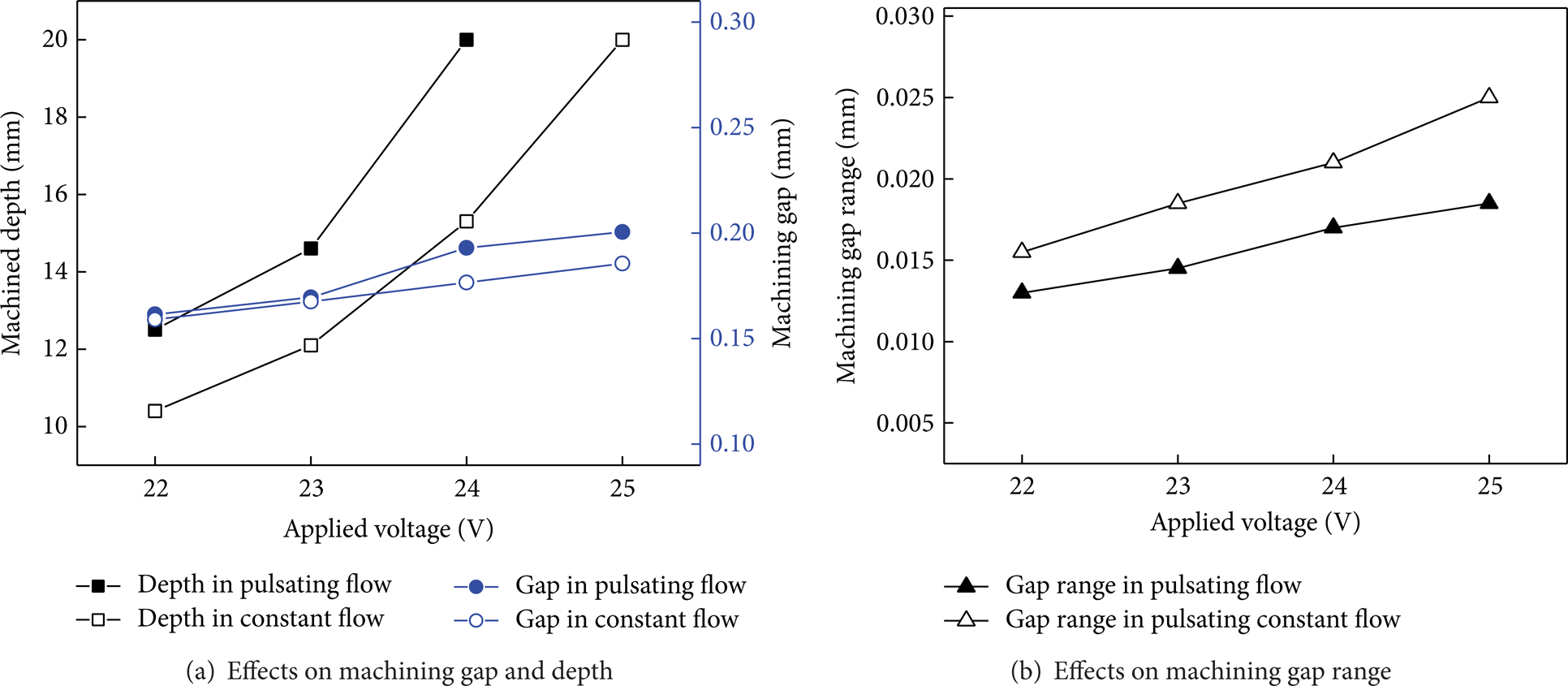
Effects of applied voltage on deep hole drilling.
Figure 8(a) shows the effects of applied voltage on the machining gap and the maximum machining depth. Figure 8(b) shows the effects on the machining gap range. In both of these two flow conditions, with increasing applied voltage, the averaged machining gap, the machining gap range, and the maximum machining depth all increase. When the voltage is increased, the current density increases and the material removal volume per unit time increases, which means a larger machining gap.
Comparing the results obtained with the same voltage, it can be concluded that the machining gap drilled with pulsating flow is nearly the same as that with constant flow, while the machining gap range decreases; that is, the machining accuracy is improved. Furthermore, the maximum machining depth with pulsating flow is obviously superior to that with constant flow. When the voltage is 22 V, the hole drilled with the constant flow has a 0.159 mm gap and a 0.016 mm gap range, while the hole drilled with the pulsating flow has a 0.161 mm gap and a 0.013 mm gap range. The machined depth with pulsating flow is 12.5 mm, which is about 20% deeper than that with constant flow (10.4 mm). When the voltage is 24 V, the maximum machined depth with pulsating flow is 20 mm, which is 30% deeper than that with constant flow (15.3 mm).
4.5. Effects of Electrode Feed Rate on Deep Hole Drilling
Figure 9 shows the effects of electrode feed rate on deep hole drilling with constant flow and with pulsating flow, respectively. The constant pressure is 0.5 MPa. The pulsating flow is 5 Hz in frequency, 0.2 MPa in amplitude, and 0.5 MPa in averaged pressure. The electrode feed rate varies between 0.6, 0.8, and 1.0 mm/min. The applied voltage is 24 V.
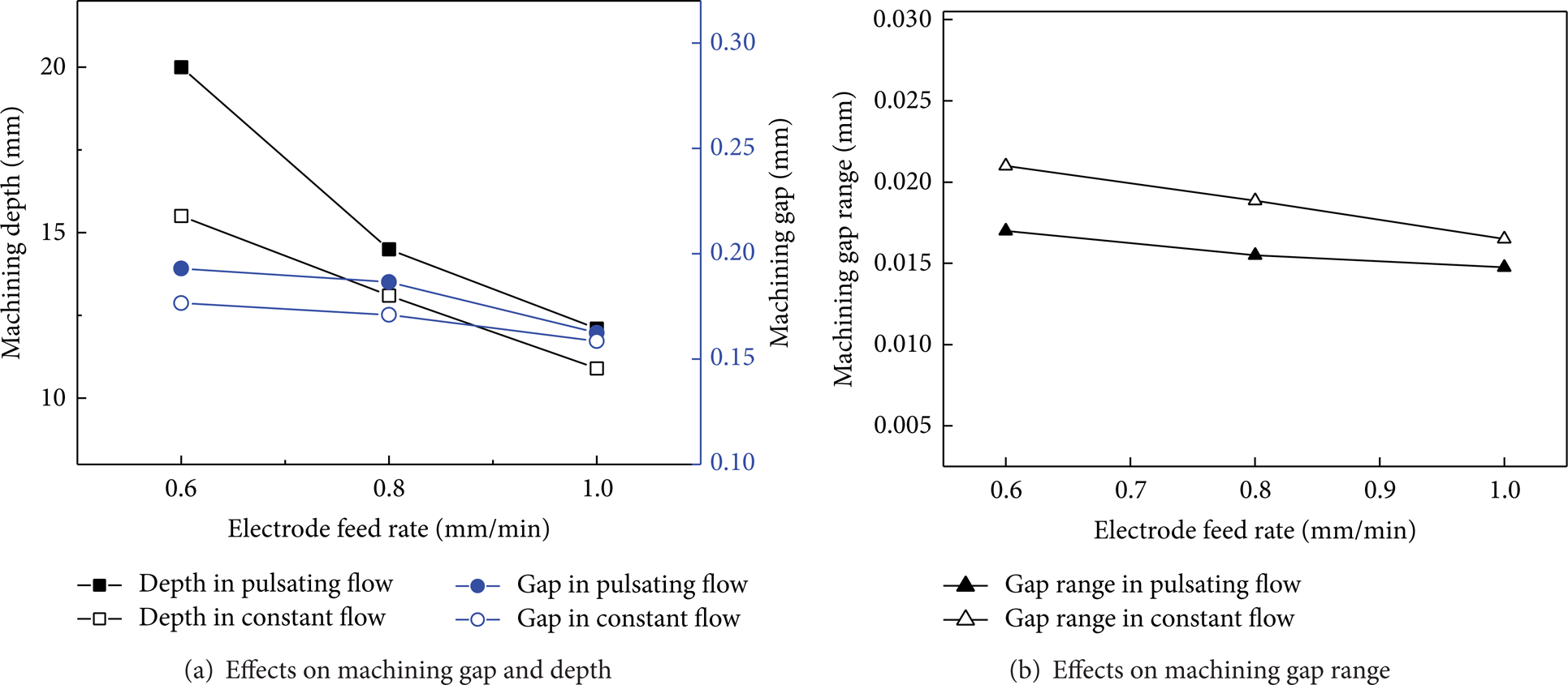
Effects of electrode feed rate on deep hole drilling.
Figure 9(a) shows the effects of electrode feed rate on the machining gap and the maximum machining depth. Figure 9(b) shows the effects on the machining gap range. In both of these two flow conditions, with increasing electrode feed rate, the averaged machining gap, the machining gap range, and the maximum machining depth all decrease. When the electrode feed rate is increased, the time in which the current attacks the workpiece per unit length decreases and the material removal volume decreases, which means a smaller machining gap.
Comparing results for the same electrode feed rate, the maximum machining depth with pulsating flow is obviously superior to that with constant flow. When the feed rate is 0.6 mm/min, the machined depth with pulsating flow is 20 mm, which is about 30% deeper than that with constant flow (15.5 mm).
4.6. Drilling of Deep Hole in Titanium Alloy
From the results presented in Section 4, it can be concluded that using a parameter group with a high voltage and a low electrode feed rate contributes to enhancing the maximum machining depth. In addition, pulsating flow is effective in enhancing the maximum machining depth and the homogeneity of the deep hole diameter. With the optimized parameters of 5 Hz frequency, 0.2 MPa amplitude, 0.5 MPa average pressure, 25 V applied voltage, and 0.6 mm/min electrode feed rate, a deep hole of 20 mm in depth and 1.97 mm in average diameter was machined in titanium alloys, as shown in Figure 10.

A deep hole machined with optimized parameters.
5. Conclusions
This paper proposed a method of electrochemical drilling with pulsating electrolyte flow, and the effects of pulsating flow on deep hole drilling were experimentally investigated. The conclusions can be summarized as follows.
Pulsating flow varying with the sinusoidal rule is effective in accelerating by-product removal and in reducing the adhesion of flocculent products to the hole inside wall.
The correct increase of pulsation frequency and amplitude could enhance by-product removal and the homogeneity of the machining gap, but an excessive increase is harmful to the process stability.
Pulsating flow is superior to constant flow in enhancing both maximum machining depth and machining accuracy.
Conflict of Interests
The authors declare that there is no conflict of interests regarding the publication of this paper.
Footnotes
Acknowledgments
The authors acknowledge the financial support provided by the National Natural Science Foundation of China (51175258) and the Jiang Su Natural Science Foundation (BK20131361).