
Abstract
The redundant design principle of weak coupling magnetic bearing system for aeroengine is put forward. A redundant design scheme of weak coupling magnetic bearing system is provided including radial and axial magnetic bearings and their control system. The performance of the weak coupling redundant magnetic bearing is analyzed with the finite element method and then compared with the strong coupling redundant magnetic bearing. The weak coupling redundant magnetic bearing has some advantages in both redundancy and load bearing capacity under the circumstance of either no failure or partial failure in the coils. In view of the increase in the number of electronic components in the control system, both reliability and redundancy are evaluated comprehensively. A compromise solution of 12-pole structure for the weak coupling redundant magnetic bearing is recommended.
1. Introduction
Magnetic bearings possess a number of advantages, such as long life; being contact-free, abrasion-free, and lubrication-free; and adapting to high rotation speed. Applying magnetic bearing onto the aeroengine can cancel the engine accessory gearbox, lubrication systems, the bearing sealing device, and the seal pressurization system. Consequently, the magnetic bearings application in the aeroengine becomes a worldwide research hotspot. In the 20th century, the United States developed an IHPTET program which investigated magnetic bearing multi- or all-electric aeroengine. In 1997, a combined fleet of Europe developed AMBIT research program that specialized in studies on magnetic bearing of the aeroengine [1, 2].
Magnetic bearings belong to complex electromechanical integration products, and the reliability is an important performance index. Aeroengine does not only require magnetic bearings with high reliability, but even for magnetic bearings in the case of some components failure, the remaining components can reconfigure based on a certain criterion, continue to provide certain load bearing capacity, to guarantee the safety of the aircraft engine operation. Redundancy design of magnetic bearing is one of the ways to improve reliability.
Since the 1990s, various countries began to study the redundant design of magnetic bearing. A redundant scheme of radial magnetic bearing was presented by Storace A F, regarding the two opposite poles out of the six poles as an independent control axis; then, the whole magnetic bearing was made up of three independent control shafts arranged every 60° apart. At the same time, he also put forward the double ring redundancy scheme of axial magnetic bearings, namely, two ring redundant axial magnetic bearings [3]. Bias current linearization method is proposed by Maslen and Meeker, and the method of control current reconstruction is used to realize the fault-tolerance of the magnetic bearing during certain failures. A maximum load bearing capacity can be achieved through the optimization of the reconstruction matrix without excessive redundant coil [4]. Radial magnetic bearing with a multiple independent-driving structure is researched through simulation by Wu et al. using the bias current linearization method. The results show when there is failure of partial coils in the system, compared with the current distribution method, the controller reconfiguration method has better fault-tolerant properties [5]. Based on the coordinate transformation of the displacement sensor, a control algorithm for actuator fault tolerance is investigated by Cui and Xu on a six-pole radial magnetic bearing. Experiments verify that the algorithm is effective as when a sensor and three coils fail at the same time, the rotor can still be stable suspended [6]. Research on a magnetic suspended rotor with double DSP controller is presented by Yu et al. which shows that when the rotor rotates at 30000 r/min, the controller can quickly judge fault in DSP and switch to the standby one and the rotor rotates stably during the switching process [7, 8].
2. The Redundant Design Scheme of Magnetic Bearing Used for Aeroengine
A redundant scheme with the reconstruction capacity including radial magnetic bearings, axial magnetic bearing, sensors, and control systems is proposed in this paper.
2.1. The Radial Magnetic Bearing Redundant Design Scheme
The strong coupling structure for radial magnetic bearing is shown in Figure 1(a). The structure that was put forward by Storace A F with 12 poles and NSNS arrangement is shown in Figure 1(b); it can work normally with any two of the three control shafts functioning. And the radial magnetic bearing redundant scheme proposed in this paper is shown in Figure 1(c), in which there is a structure separation between two magnetic-pole pairs to weaken the magnetic coupling. Furthermore, with the NNSS arrangement, the magnetic coupling is weakened again. So it is called weak coupling radial magnetic bearings redundant structure. Each pole has a coil, each coil is connected with a power amplifier, and each power amplifier can switch on different conditions. When any coil or power amplifier fails, the rest of the components are available to participate in the reconstruction of a new magnetic bearings system.

Radial magnetic bearing redundant design.
2.2. The Axial Magnetic Bearing Redundant Design Scheme
The traditional axial magnetic bearing which adopts single ring coil structure is presented in Figure 2(a). Once the coil is failed, the axial magnetic bearing becomes invalid. The structure that was put forward by Storace A F and adopts double-ring coils structure is presented in Figure 2(b). When a coil is failed, the other one can still meet the working requirements. And the axial magnetic bearing proposed in this paper is presented in Figure 2(c), which adopts six-ring coils structure and each ring owns a set of independent and complete structures.
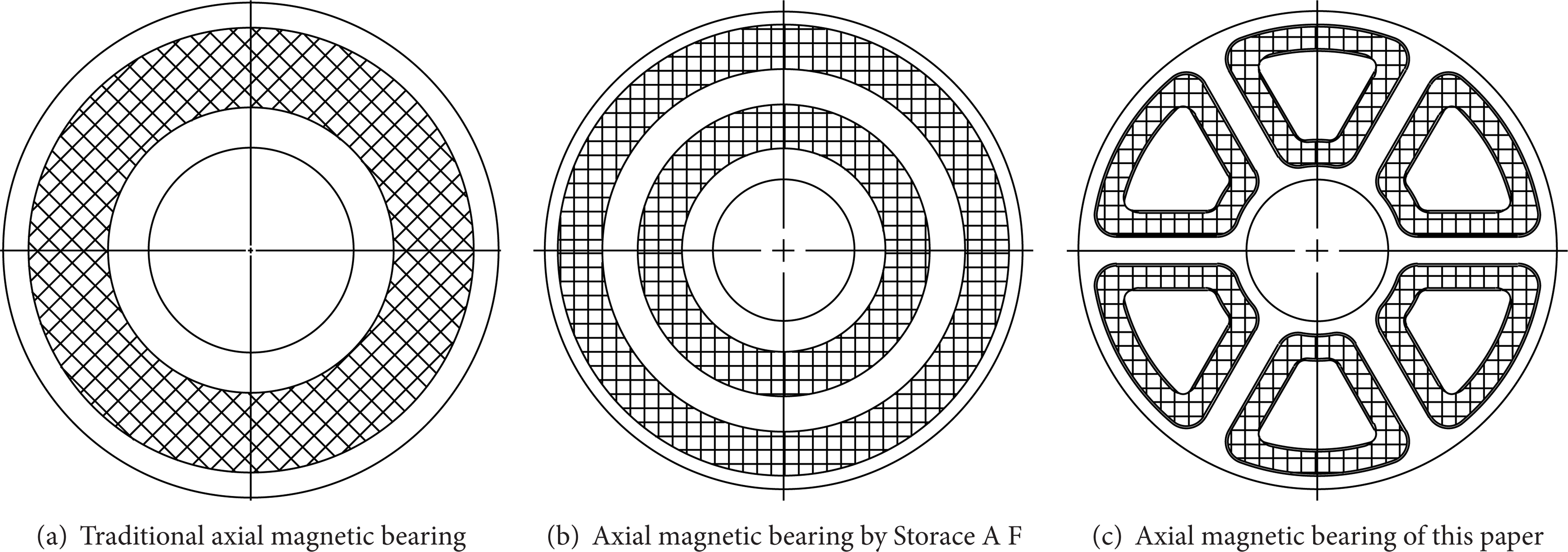
Axial magnetic bearing redundant design.
2.3. Redundant Design of Control System
In this paper, the redundant design for magnetic bearing involves a large number of coils and power amplifiers, and with conventional scheme that has been adopted, the number of power amplifiers is excessive which will lead to an excessively complicated control system. To solve problems like this, the power amplifier is decomposed into two parts; one is the power bridge and the other is loop control unit. Then the power bridge adopts redundant structure, the schematic diagram which is shown in Figure 3. The programmable power output array completes the logic connection between power bridges and coils when DSP controller performs the current distribution logic for each coil. With this kind of structure, the power amplifier can still work normally when only a half of the power bridges are remaining and there is no need for any excessive functional components.

The structural schematic diagram of the power amplifier.
3. The Residual Bearing Capacity Analysis of Magnetic Bearing
3.1. The Residual Bearing Capacity Analysis of Radial Magnetic Bearing
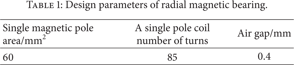
The residual bearing capacity of the strong coupling and weak coupling structures in Figures 1(a) and 1(c) is analyzed with the electromagnetic module in ANSYS. The analysis premises on the same magnetic pole area, same coil current, and the same working air gap without the saturation of magnetic pole. The structure design parameters of radial magnetic bearings are shown in Table 1.
Design parameters of radial magnetic bearing.
The relationship between electromagnetic force and coil current is shown in Figures 4 and 5 when Figure 4 corresponds to no coil failure and Figure 5 corresponds to four coils failure.

The relationship between magnetic force and coil current without coil failure.

The relationship between magnetic force and coil current with 1, 6, 7, and 12 coils failure.
When there is no coil failure, the values of electromagnetic force in weak coupling structure and strong coupling structure are very close. With four coils failure, electromagnetic forces in both structures reduce in a degree, but the electromagnetic force of weak coupling structure reduces greater than that of strong coupling structure in both X and Y directions.
3.2. The Residual Bearing Capacity Analysis of Axial Magnetic Bearing
The residual bearing capacity of the double-ring and six-ring structures in Figures 2(b) and 2(c) is analyzed with the electromagnetic module in ANSYS. The analysis premises on the same magnetic pole area, same coil current, and the same working air gap without the saturation of magnetic pole. For the six-ring coils structure, once there is a coil failure, the maximum residual bearing capacity can be obtained based on the principle that the additional bending moment on the supporting shaft is zero. With a constant coil current under different conditions of coil failure, the ratio of the residual bearing capacity out of the original bearing capacity is shown in Figure 6.

Ratio of residual bearing capacity under different conditions of coil failure for six-ring coils structure.
It can be seen from Figure 6, based on the zero additional bending moment principle above and the constant currents in coils, there are three kinds of residual bearing capacity ratios corresponding to five kinds of coils failure.
In the actual redundant design, the iron core and the coils of a magnetic bearing should have certain performance redundancy, which means the coil current can be increased in the case of coil failure. Capacity of two axial magnetic bearings with different redundant structures is compared still using the electromagnetic module in ANSYS through compensating the current when failure occurs in part of the coils. Then, the result is shown in Table 2.
Bearing capacity after current compensation under partial failure of two axial magnetic bearings.

Double-ring coils structure can work properly with only one ring of the two coils that fails, while the six-ring coils structure can work properly through compensating the coil current as long as it does not appear with the adjacent three or more consecutive coil failures. As is shown in Table 2, the two kinds of structures can both reach the initial bearing capacity through coil current compensating. And with the same compensation current, the six-ring coils structure is obviously better than the two-ring coils structure in the bearing capacity. So the six-ring structure here is better than the two-ring structure in both redundancy and bearing capacity.
4. Reliability Analysis of Redundant Design of Magnetic Bearing
Redundant design of magnetic bearings can efficiently improve the reliability of magnetic bearings but with an increase in the number of control system components. With the increase of the number of components, the probability of component failure also increases, which will result in a decrease in reliability of the magnetic bearings system. Therefore, it is necessary to research the relationship between the redundancy and reliability of the magnetic bearing system to obtain the best point.
The reliability analysis on redundant design of magnetic bearing is carried out as follows with the redundancy design scheme of magnetic bearings proposed in this paper. Related statistics shows the service life of high quality electronic components is generally obeying exponential distribution. Therefore, the probability density function of the service life is as follows:

whereλ represents the failure rate.
Service life distribution function can then be written as follows:

The average value of service life can be deduced. Consider

According to the functions above, the average service life for electric components like resistor, capacitor, diode, and triode is selected as 106 hours, which means λ = 10−6/h [9]. The reliabilities of coils, amplifier, and the DSP controllers for working 2000 hours (T = 2000 h) continuously can then be deduced, respectively, as follows.
For coils, the reliability is so much higher than the other electric components that it can be set as 99.99% in this paper.
Amplifiers commonly have multiple power bridges in parallel and a single power bridge is installed with four components in series. So the reliability should be calculated with the functions below. The outcome is then 99.99% when n = 4 here. Consider

where from R1 to R4 represent the reliability of the four components in a power bridge, respectively.
RAmplifier and RPowerBridge represent the reliability of an amplifier and a single power bridge, respectively.
As for DSP controller, it can be treated as a system made up of three units in series which are CPU, signal-input channel, and signal-output channel. Besides the nonsource components, there is a need for at least 2 components for CPU, 4 components for signal-input channel, and 6 components for signal-output channel. So the reliability of a DSP controller can be calculated by the following function [9]. The outcome here is 97.6% after calculation. Consider

where RDSP represents the reliability of a DSP controller.
On the basis of functions (4) and (5), the reliability of a magnetic pole can be calculated, as well as the reliabilities of the magnetic bearing systems with function (6). Consider

where R p is the reliability of a single magnetic pole.
Rsys represents the reliable probability of the magnetic bearing system with k poles failure when the total number of magnetic poles is n.
With all the functions above, the reliabilities of the magnetic bearing systems with different number of poles can be obtained, which is shown in Table 3.
Reliable probability of magnetic bearing system with different number of poles.

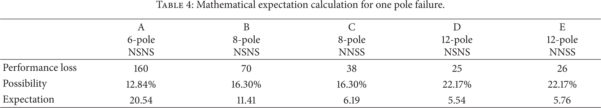
The redundancy evaluation for magnetic bearing system should comprehensively take both components reliability probability and performance loss of redundant structure during coil failure into consideration. The performance loss for five different stator structures of magnetic bearings during a pole failure is presented in Figure 7 [10]. Treating the data in Figure 7 as the impact on the performance of magnetic bearing resulted from the redundant structure, the reliable probability of the system components as the influence on the reliability of magnetic bearing, a comprehensive evaluation on both redundancy, and reliability of the redundant design scheme proposed in this paper is made. The outcome calculated with mathematical expectation method is shown in Table 4.
Mathematical expectation calculation for one pole failure.
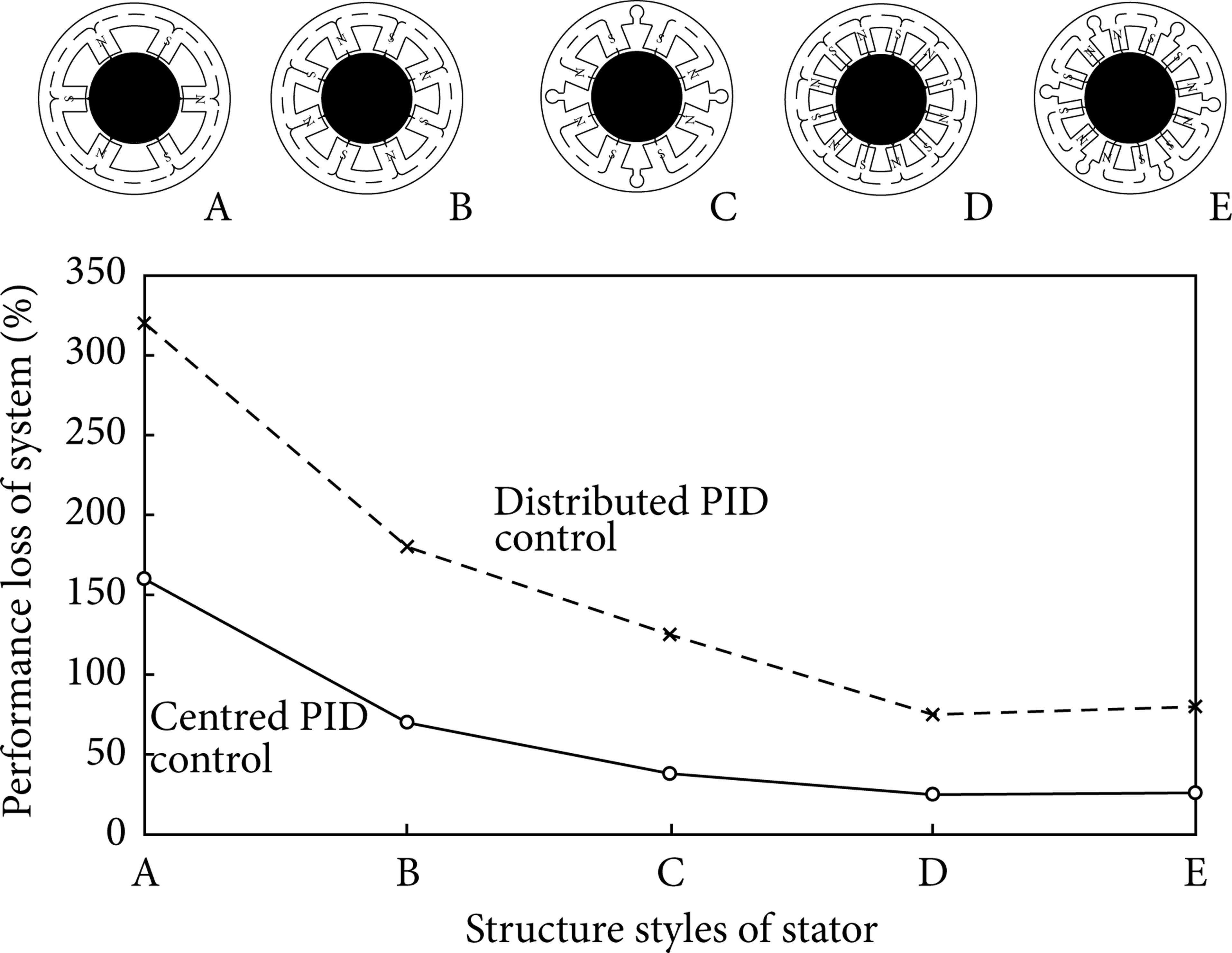
Plot of bearing structure against percentage loss in performance during a coil failure solid-centralized and dotted-decentralized.
It can be seen from Table 4 that redundant structure with 12 poles and NSNS arrangement has the minimum expectation of the performance loss. In other words, when electronic components have a long service life, the performance loss of magnetic bearing during coil failure takes the dominant place. So a conclusion can be drawn that redundant structure with 12 poles is better when taking both redundancy and reliability into consideration.
5. Summary
In allusion to the high reliability requirements of aeroengine, the redundant design of magnetic bearing has been discussed and researched in this paper. The result shows that the bearing capacity of the redundant design scheme of magnetic bearing proposed in this paper is better than their corresponding traditional structure. The new structures have a higher redundancy and can allow more components failure without the decrease in bearing capacity which means a higher reliability of the magnetic bearing system. So balancing the system reliability and redundancy, redundant design of magnetic bearing with 12 poles is better.
Footnotes
Appendix
The symbols, acronyms, and variable definitions used in this paper are all listed in Table 5.
Conflict of Interests
The authors declare that there is no conflict of interests regarding the publication of this paper.
Acknowledgments
The authors gratefully acknowledge the support of this research by the National Natural Science Foundation of China (no. 51205300, no. 51175390, and no. 51147004).