
Abstract
With outstanding advantages, such as large workspace, flexibility, and lightweight and low inertia, cable-driven parallel manipulator shows great potential for application as the exoskeleton rehabilitation robot. However, the optimal design is still a challenging problem to be solved. In this paper, the optimal design of a 3-DOF (3-degree-of-freedom) cable-driven upper arm exoskeleton is accomplished considering the force exerted on the arm. After analysis of the working conditions, two promising configurations of the cable-driven upper arm exoskeleton are put forward and design parameters are simplified. Then, candidate ranges of two angle parameters are determined with the proposed main workspace requirement. Further, global force indices are defined to evaluate the force applied to the arm by the exoskeleton, in order to enhance the system safety and comfort. Finally, the optimal design of each configuration is obtained with proposed force indices. In addition, atlases and charts given in this paper well illustrate trends of workspace and force with different values of design parameters.
1. Introduction
With the improvement in social living condition and the advance in medical technology, the average life expectancy grows continuously, and elderly population increases dramatically [1]. At the same time, accelerating pace of life and increasing life pressure cause high incidence of cardiovascular and nervous system diseases and finally lead to more stroke hemiplegia [2]. Luckily, the human central nervous system possesses perfect plasticity [3, 4]. Through timely and effective rehabilitation training, neurological damage and complications can be significantly reduced, movement function can be rebuilt, and the patient's self-care ability can be enhanced. However, growing elderly population and stroke patients challenge the rehabilitation therapy greatly. Traditional artificial rehabilitation, implemented manually by the physician, is unsustainable because of the following. (a) Training parameters cannot be accurately controlled, and treatment effect depends on the physician ability. (b) Objective evaluation of rehabilitation is not available, and treatment programs cannot be adjusted accordingly. (c) There are low efficacy and high labor intensity. Then, rehabilitation robots emerge and solve the above problems.
Structural optimization is always a primary issue in the rehabilitation robot research. Structure determines performance and thereby determines provided rehabilitation therapy. Based on different traction patterns, rehabilitation robots can be subdivided into two categories, such as terminal traction [5, 6] and exoskeleton [7, 8]. Take arm rehabilitation robots for example. As shown in Figure 1, terminal traction rehabilitation robot tows the hand (terminal of the arm) to rebuild the arm movement function. Correspondingly, exoskeleton rehabilitation robot possesses similar structure and same degrees of freedom with the arm, being attached to the arm and driving the joints directly. Due to simple structure, terminal traction rehabilitation robots appear and are applied firstly [9]. However, since such rehabilitation robot cannot control the independent movement of single joint, targeted and efficient training is difficult to be carried out. Further, although better than the terminal traction style, the exoskeleton rehabilitation robot is still not a perfect answer. Reasons are as follows. Firstly, the structure of human shoulder joint is so complex that its rotation center changes with the orientation. Rigid exoskeleton only models the shoulder joint as the spherical joint and will restrict its movement. Secondly, rigid exoskeleton is bulky, increases the human arm inertia dramatically, and severely changes the dynamics of the human arm.

Arm rehabilitation robots ((a): terminal traction, (b): exoskeleton).
In view of the above questions, Yang combined cable-driven parallel manipulator with exoskeleton and first proposed the concept of cable-driven arm exoskeleton [10]. Cable-driven parallel manipulator consists of the base and the end effector, connected together with lightweight cables instead of rigid limbs [11, 12]. Cable-driven exoskeleton well inherits advantages of cable-driven parallel manipulator, namely, large workspace, flexibility, and lightweight and low inertia [13, 14], and greatly improves the performance of rehabilitation robots. Although just emerging, some research on the cable-driven rehabilitation devices has already been carried out [15, 16].
Optimal design of the cable-driven exoskeleton is an important theoretical issue as well as an essentially practical approach to improve the rehabilitation performance. The kernel of cable-driven arm exoskeleton design is the upper arm part (shoulder module), considering its requirements of large workspace and heavy load [17, 18]. Based on workspace analysis, Mustafa et al. and Yang et al. proposed a six-cable parallel manipulator to implement the rotation of upper arm and gave several sets of available dimension parameters [19, 20]. Mao and Agrawal optimized the upper arm part of the proposed cable-driven arm exoskeleton [21, 22]. However, due to analysis complexity, existing research on optimal design is based on limited design options and fails to illustrate the relationship between design parameters and manipulator performances.
In this paper, two promising configurations of the cable-driven upper arm exoskeleton are proposed at first, and candidate ranges of design parameters are determined with workspace atlases. Then, global indices are defined considering the force exerted on the arm by the exoskeleton in the required workspace. Finally, the optimal result is obtained to minimize the maximum force index. In summary, optimal design of the cable-driven upper arm exoskeleton is carried out with thorough analysis, and intuitive relation between manipulator performances and design parameters is given. The remainder of this paper is organized as follows. In the next section, based on the working condition analysis, structure of the upper arm exoskeleton is determined, and design parameters are given with established coordinate systems. In Section 3, two global force indices of the exoskeleton are defined considering the comfort and safety. Workspace analysis is carried out in Section 4, while the optimal design of the cable-driven exoskeleton is accomplished with proposed global force indices in Section 5. Finally, conclusions of this paper are given in the last section.
2. Structure Design
The shoulder joint has three rotational degrees of freedom, including two swings (as shown in Figure 2(a), flexion/extension, and Figure 2(b), adduction/abduction), as well as one self-rotation around the upper arm axis (as shown in Figure 2(c), inward/outward). The self-rotation range is relatively limited and not necessarily coupled with other two rotational degrees of freedom. Therefore, the optimal design is carried out focusing on these two swings. Considering the movement range of human upper arm, we define the main workspace, as shown in Figure 3, which is a spherical surface. Central angles of its horizontal and side projections are 120°.

Shoulder's rotational degrees of freedom.

Main workspace of the upper arm (left: top view, right: side view).
Since cables can only be pulled but not pushed, n-DOF cable parallel manipulator needs at least n + 1 driving cables, according to the vector closure principle [23]. Thus, the 3-DOF cable-driven upper arm exoskeleton needs at least four driving cables. Considering the convenience of installment and arrangement, four-cable parallel manipulator is adopted in this paper, as shown in Figure 4. The end effector of the cable parallel manipulator is a ring (usually called the arm cuff), where the arm is fixed inside with the inflated tension device. The base of the cable parallel manipulator is a major arc with the central angle of 240° (called the shoulder cuff). The shoulder cuff is attached to rigid support rather than the human shoulder.

Cable-driven upper arm exoskeleton.
To facilitate analysis, coordinate systems of the object exoskeleton are established as shown in Figures 4 and 5. A Cartesian coordinate system {
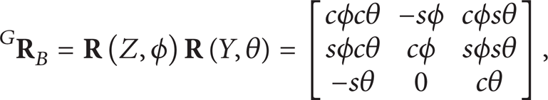
where s stands for the sine operation, c stands for the cosine operation, θ = 30°, and ϕ = 30°.

Kinematic model of the cable-driven upper arm exoskeleton.
The end-effector frame {
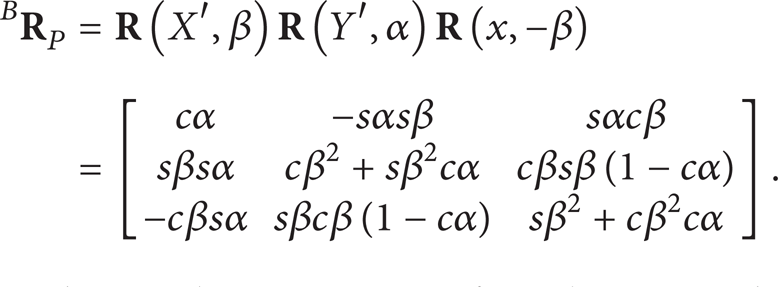
Considering the symmetry of workspace and extern force, the cable-driven upper arm exoskeleton should also be symmetric in structure. So, its structure can be described by four angle parameters and three length parameters in general. Angle parameters include e1 angle between O′B 1 (O′B 4 ) and the positive of z′-axis, e2 angle between O′B 2 (O′B 3 ) and the positive of z′-axis, and e3 angle between oP 2 (oP 3 ) and the positive of z-axis, as well as e4 angle between oP 1 (oP 4 ) and the positive of z-axis. Length parameters are composed of base (shoulder cuff) radius R, end-effector (arm cuff) radius r, and initial distance h between the base and the end effector. In order to simplify the following optimization design, number of design parameters must be reasonably reduced.
Firstly, length parameters are normalized and become dimensionless quantities. Let us choose h as the unit length. Then, given the size of the human upper arm, design space of length parameters can be determined as R ∈ [0.5, 1], r ∈ [0.3, 0.5]. Considering practical application, crossovers should be avoided in cable arrangement. And, it is better to decrease connection points between cables and the end effector (the arm cuff). Based on the planar 3-DOF cable-driven parallel structure and taking the effect of gravity into account, two promising configurations can be obtained, as shown in Figures 6 and 7. In configuration I, e2 = 0°, e3 = e4, there are only two angle parameters left, and the design space is e1 ∈ [0°, 120°] and e4 ∈ [0°, 180°]. In configuration II, there are three angle parameters left (e3 = 0°). And, the angular design space becomes e1(e2) ∈ [0°, 120°], e2 ≤ e1, and e4 ∈ [0°, 180°].
Configuration I of the cable-driven upper arm exoskeleton.

Configuration II of the cable-driven upper arm exoskeleton.
3. Tension and Force Analysis
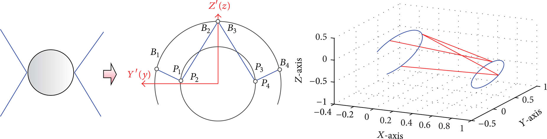
The dynamic model for the cable-driven upper arm exoskeleton can be written in the standard form, adopting the Lagrangian method. Consider the following:

where
Since the cable-driven upper arm exoskeleton usually moves quite gently and slowly, the static analysis is carried out in this paper and the static workspace is adopted in the next section. In static state, (3) can be written as
In order to figure out cable tensions, the Jacobian matrix must be deduced at first. With the deduced rotation matrices, the position of the end effector (arm cuff) can be expressed in the global frame as (

Then, point P i can be described as

Considering the unidirectional cable force, the cable vector can be derived in the global frame as (from point P i to point B i )

Further, the cable length and the unit cable vector can be given as

The torque applied in the shoulder by the gravity force can be expressed as
The torque generated by the ith cable tension can be obtained as

Finally, the Jacobian matrix can be deduced as

Considering the comfort and safety, the force exerted on the arm by the exoskeleton must be checked and controlled. The shoulder cuff is attached to the rigid support, while the arm cuff is fixed on the human arm. So force exerted through the arm cuff is chosen as an important performance index to carry out the optimization design. Local Arm Force Index (LAFI), which is the sum of cable forces exerted along the upper arm under the unit gravity, can be expressed as

where n is the number of driving cables.
In order to evaluate the performance of the exoskeleton in the whole workspace, two global force indices can be defined accordingly. In detail, MFI (Maximum Force Index) and AFI (Average Force Index) can be expressed separately as

where W is the required workspace. Generally, smaller values of the MFI and the AFI promise better comfort and safety.
4. Workspace Analysis
The static workspace [24] is adopted in this section, which is a set of points where the upper arm can be supported in the static equilibrium with the gravity. Since the cable number is larger than the degrees of freedom of the exoskeleton, the cable tension can be solved with the pseudoinverse matrix as

where
Each point in workspace must satisfy two basic requirements. Firstly, the rank of the corresponding Jacobian matrix equals three. Secondly, each cable tension deduced from (14) under the minimum tension sum condition must be greater than zero. There are several calculation methods [25, 26]. Main workspace requirement of the upper arm exoskeleton is an essential condition that must be satisfied, while proposed force indices are used to determine the optimal design. The gravity is considered as the unit force and exerted on the geometric center of arm cuff. With the workspace analysis, candidate ranges for angle parameters e1 and e4 are determined, which will ease the calculation burden in the optimal design stage.
4.1. Workspace of Configuration I
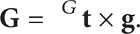
Let us discuss angle parameters at first, namely, e1 and e4 (e3). When the length parameters are determined (r = 0.3, R = 0.5), the ratio of available workspace to the required main workspace of configuration I is shown in Figure 8. We can find the following.
The design space of e1 and e4 (e3) can be approximately divided into two sections by the line of e1 = e4.
In the upper region (e4 > e1), e1 is the major factor. With a given e4, the available workspace increases with the increase of e1. In the lower region, e4 is the major factor. With a given e1, the available workspace enlarges with the increase of e4.
The candidate area where the main workspace requirement is met lies in the lower right region below the line of e1 = e4, and roughly e1 ∈ [100°, 120°], e4 ∈ [20°, 120°].
Workspace atlas of configuration I in the design space of e1 and e4.
In this part, the workspace of configuration I is analyzed with angle parameters e1 and e4 (e3), and cable distribution is determined in general.
4.2. Workspace of Configuration II
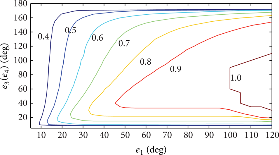
With given length parameters (r = 0.3, R = 0.5), the ratio of available workspace to the required main workspace of configuration II is shown in Figure 9 (e2 = 30°). We can see the following.
The angular design space of e1 and e4 can also be divided into two sections by the line of e1 = e4. In the upper region (e4 > e1), e1 is the major factor. However, in the lower region, e4 is the major factor.
The area where the main workspace requirement is met is in the upper right region above the line of e1 = e4, and roughly e1 ∈ [100°, 120°], e4 ∈ [140°, 180°].
Workspace atlas of configuration II in the design space of e1 and e4.
The workspace of configuration II is analyzed with angle parameters e1 and e4, and another angle parameter e3 will be discussed in the next section with length parameters. In summary, the main workspace requirement of the upper arm can be met by the two proposed configurations.
5. Force Analysis
As mentioned before, force applied to the upper arm by the cable-driven exoskeleton is an important performance evaluation. In this section, defined MFI and AFI are adopted.
5.1. Configuration I
After the main workspace requirement is satisfied, MFI and AFI of the exoskeleton can be calculated according to (13). In each point of the length design space, all available sets of e1 and e4 are calculated based on the candidate ranges obtained in Section 4. Then, the average value of AFI for available sets of e1 and e4 is figured out and shown in Figure 10. In addition, the minimum value of MFI for available sets of e1 and e4 in the candidate ranges is determined and shown in Figure 11. Figures 10 and 11 tell that the cable-driven upper arm exoskeleton with larger base radius or smaller end-effector radius has an advantage of reducing the force exerted on the arm, which brings more comfort and safety.

Average AFI value of configuration I.

Minimum MFI value of configuration I.
5.2. Configuration II
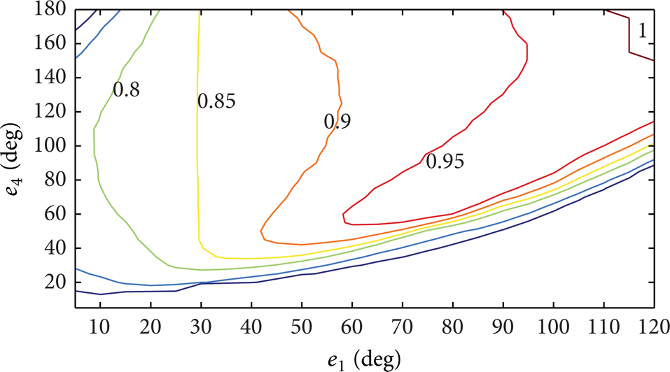
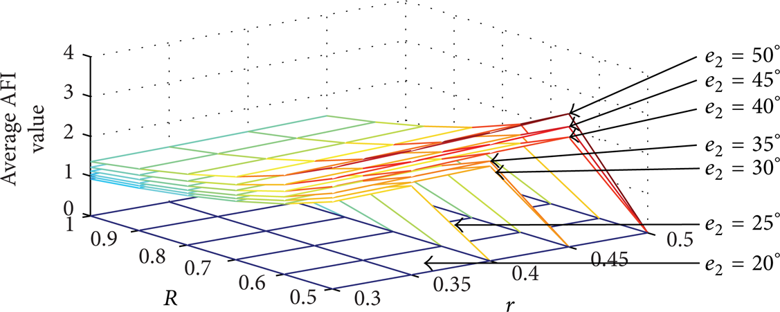
For configuration II, angle parameter e2 is analyzed with length parameters R and r. The arm force charts are shown in Figures 12 and 13. In these two figures, if the force value is zero, it means that the main workspace requirement cannot be met with this set of length parameters, regardless of values o f e1 an d e4. We can tell the following.
With the increase of e2, the adoptable range of length parameters increases, which can provide more choices for the detailed design.
When the angle parameter e2 is determined, the force exerted on the arm by the exoskeleton decreases with the shrinking of the end-effector radius and the increase of the base radius.
The minimum force exerted on the arm can be obtained under the condition that e2 = 25°, r = 0.3, and R = 1.
Average AFI value of configuration II.

Minimum MFI value of configuration II.
5.3. Discussion
With the optimal design parameters deduced above, the MFI value in the required main workspace of the exoskeleton can be figured out. When adopting optimized design parameters r = 0.3, R = 1, e1 = 100°, e2 = 0°, and e3 = e4 = 90°, the LAFI value of configuration I exoskeleton is shown in Figure 14. The maximum LAFI value (MFI value) is only 1.527. Similarly, when using optimized result r = 0.3, R = 1, e1 = 120°, e2 = 25°, e3 = 0°, and e4 = 180°, the LAFI value of configuration II exoskeleton is shown in Figure 15. The maximum LAFI value (MFI value) of the optimal configuration II is only 1.168. Besides, there are only two connection points between cables and arm cuff in each optimal configuration. Comparison of these two figures indicates that MFI value distributions are quite different from each other. The MFI value of configuration I generally appears at the left and right sides of the main workspace, while the location of the MFI value in configuration II is relatively lower. Since the cable-driven parallel manipulator can be easily reconfigured, the exoskeleton can be adjusted conveniently between optimal configurations I and II, according to different rehabilitation training trajectories, in order to further lower the MFI value and be more comfortable.

LAFI value distribution of the optimal configuration I.

LAFI value distribution of the optimal configuration II.
6. Conclusion
In this paper, the optimal design of the 3-DOF cable-driven upper arm exoskeleton is investigated, based on the four-cable parallel manipulator and considering the force exerted on the arm. Given the influence of gravity, two configurations of the exoskeleton are proposed. In configuration I, e2 = 0° and e3 = e4, while only e3 = 0° for configuration II. Adopting the proposed main workspace of upper arm, candidate ranges of e1 and e4 are determined; namely, e1 ∈ [100°, 120°], e4 ∈ [20°, 120°] for configuration I and e1 ∈ [100°, 120°], e4 ∈ [140°, 180°] for configuration II. In order to improve the comfort and safety, global force indices AFI and MFI are defined and optimal designs of configurations I and II are accomplished accordingly. With the optimal structure parameters, MFI value of configuration I is reduced to 1.527, and the MFI value of configuration II is only 1.168.
In addition, trends of workspace and force are analyzed with given atlases and charts. Workspace atlases are established in angular design space of e1 and e4 and can be divided into two sections by the line of e1 = e4. The candidate area of configuration I appears in the rightmost part under the line, while the candidate area of configuration II appears also in the rightmost part but above the line. With force analysis, it is pointed out that the cable-driven upper arm exoskeleton with larger base radius and smaller end-effector radius has an advantage of reducing the force exerted on the arm, which also brings more comfort and safety. Considering the feature of easy to reconfigure, MFI value of the cable-driven upper arm exoskeleton could be further reduced with proper adjustment between optimal configurations I and II according to different training trajectories.
Conflict of Interests
The authors declare that there is no conflict of interests regarding the publication of this paper.
Footnotes
Acknowledgments
The research is supported by the National Natural Science Foundation of China (nos. 51205224 and 11178012).