
Abstract
The objective of this study was to evaluate the tribological performance through investigating protective additive layer and friction coefficient and implementing the quantitative wear measurements on the rubbed surface of the sliding pairs. The specimens of oil ring were rubbed against cast iron engine cylinder liner under boundary lubrication conditions. The ring and liner surfaces were examined by optical, scanning electron microscope and atomic force microscopy. The elemental analysis of surfaces was performed by using energy dispersive X-ray spectroscopy. Surface observations showed that coating was removed from the ring surface. Higher levels of Ca, Zn, P, and S elemental ratios (0.93%, 0.45%, 1.55%, and 1.60% as atomic percent) were detected on the cylinder liner surface. Wear width, length, and depth measurements were performed by optical and atomic force microscopies on the ring and cylinder liner surface. The results showed that wear widths for oil ring were 1.59 μm and 1.65 μm; wear widths for cylinder liner were 3.20 μm and 3.18 μm; wear depths for oil ring were 100 nm; and wear depths for cylinder liner were 482 nm. Wear data were taken mostly from the additive layer points detected by SEM and X-ray measurements.
1. Introduction
Automotive manufacturers have been concerned about extending long life warranty for their products in the last decades. Extended warranty requires precise fabrication of vehicle components, providing higher strength for internal and external operating effects. Internal combustion engine cylinder liner and piston ring packs are important components of the vehicles and are also indicators of an effective engine life. Almost half of the mechanical losses at the cylinder liner-piston ring interface are due to the friction of this sliding pair in this tribological system [1]. Adhesion, abrasion, and corrosion are the dominant wear mechanisms that occur due to internal and external operating effects for liner and ring tribological system. Corrosion is one of the dominant wear mechanisms that occurs when the engine runs very cold or very hot. In particular, large increase in corrosion wear rate is noted when the cylinder wall temperature falls below the dew point of the combustion products in the cylinder [2, 3]. In order to protect the system from the corrosion wear mechanism, fully formulated oils and different coating techniques are used in internal combustion engines. Therefore, improvements in corrosion protection are becoming increasingly important for internal combustion engine manufacturers. Phosphate coating application is intended to protect the piston rings from corrosion to increase the adhesion resistance and to extend ring service life through improved corrosion resistance [4]. This coating is also formed due to a tribochemical reaction, which causes the surface of the base metal to be integrated itself as a part of the corrosion resistant film. Phosphating is also a chemical conversion coating that transforms the surface of the basis metal into a nonmetallic crystalline coating [5]. Phosphate coatings are ranged in thickness from less than 3 μm to 50 μm. Iron phosphate, zinc phosphate, and manganese phosphate are three common types of phosphate coating. In general, zinc phosphate coatings are used for oil control rings in liner and ring tribological system in vehicle engines together with small garden type engines which mainly function to control oil distribution on the cylinder liner and prevent excessive oil transporting to combustion chamber and burnt [6, 7]. By means of this low cost coating type, manufacturers attempt to extend rings life time [8]. Zinc phosphate coating varies from light to dark grey in colour and become darker as the carbon content of the underlying steel increases and it can be applied by spray, immersion, or a combination of the two [9]. Many papers have been published to investigate commonly used zinc phosphate coated piston rings but most of them focused on the surface structure of coating or coating methods and there is scant research on the tribological performance of this coating technique for piston rings. For this reason, zinc phosphate coating type has been chosen in this research. This study aims to evaluate the tribological performance of the zinc phosphate coating by investigating friction coefficient, chance of surface morphology, chemistry, and quantitative wear measurements between zinc phosphate coated oil control ring and grey cast iron cylinder liner pairs with calcium, zinc, phosphorus, and sulphur containing lubricant in boundary lubrication condition. Zinc phosphate coated oil control rings were rubbed against cylinder liners in repeated tests with a reciprocating tribotest machine to explore coating efficiency. Surfaces of cylinder liners and oil control rings were examined by optical microscopy, SEM, AFM, and EDS spectroscopy. SEM/EDS spectroscopies were used to determine surface chemistry and protective additive layers. Optical microscopy was used to measure wear widths and lengths. AFM was employed to observe surface morphology change and measure the wear depths and surface roughness on the rubbed surfaces. Both AFM measurements have been performed on flat substrate surfaces in published tribological works. There are a few studies that have carried out surface measurements on real cylinder liner surfaces which are difficult for AFM tips to perform contact mode measurements on these surfaces because of having curves and deep honing marks on their surface structures [10–13]. This paper presents AFM contact mode quantitative wear measurements on real grey cast iron cylinder substrates to evaluate wear rate of observed wear scars.
2. Materials and Methods
Zinc phosphate coated ring specimens were rubbed against cylinder liners under boundary lubricating conditions for three repeated reciprocating tests. Boundary lubrication condition was chosen for the tests to evaluate the strength of the coating which produces higher wear rates in piston ring liner system. The diameter of the oil ring (D = 68 mm) was smaller than cylinder liner (D = 88 mm) as it allows for the appropriate contact between sliding pairs. Cylinder liner test specimens were cut from a new Honda GX-390, which is a single cylinder, air-cooled, and gasoline engine. Cylinder liner substrates dimensions were 9.5 mm × 12 mm × 8 mm (w × l × h) and three pieces of substrates for oil ring were cut from a new Honda GX-200 engine spare part. Figure 1(a) shows test samples of piston rings and cylinder liners and Figure 1(b) illustrates the contact area of the piston ring on the cylinder liner surface which is approximately 4 mm2. Cylinder liner and oil control ring specimens had been cleaned ultrasonically for 5 minutes with heptane and then dried for microscopic examinations at the end of the reciprocating tests.
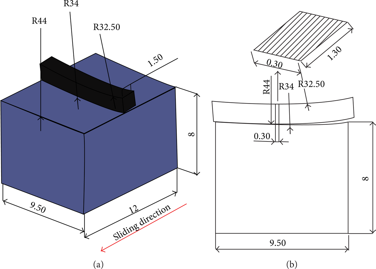
Piston ring and cylinder liner configuration of test specimens (a). Contact configuration of piston ring and cylinder liner (b).
Tests were carried out through a reciprocating tribotest machinecalled impact II (see Figure 2) which was located in Laboratoire de Mécaniques des Contacts et des Solides (Lamcos), Institut National des Sciences Appliquées de Lyon (INSA), Lyon, France. Test conditions and friction coefficient for three tests are given in Table 1. Figure 3 also shows the average friction coefficient measurements of three tests.
Test conditions.


Impact II reciprocating tribotest machine with piston ring and cylinder liner holders.

Average of friction coefficient measurements.
A conventional phosphorus containing lubricant was employed to generate boundary lubrication condition and determine performance of zinc phosphate coated ring during the tests. The specifications of test oil are given under the courtesy of Idemitsu Kosan Co., Ltd., petrochemical company in Japan. Table 2 illustrates the specifications of the test oil.
Specifications of the test oil.

3. Results
Oil control ring is a spheroidal graphite cast iron, coated with zinc phosphate, and cylinder liner is a grey cast iron. New cylinder and oil control ring specimens were analysed through optical microscopy, SEM, AFM, and X-ray techniques. New cylinder liner was honed with an angle 60-degree cross-hatched pattern and Fe, Si, Mn, C, and W elements were detected by using energy dispersive X-ray spectroscopy on the cylinder liner surface (see Figure 4). X-ray spectroscopies were performed in different magnifications to determine precise surface chemical analysis. Figure 5 illustrates the results of the X-ray analysis at magnifications 500, 1500, and 5000 with SEM. Optical microscopy and AFM images illustrate that the width and depth of honing marks are approximately 4.50 μm and 320 nm on the new cylinder liner surface, respectively (see Figure 6).

Optical, SEM, and X-ray analysis of unused cylinder liner.
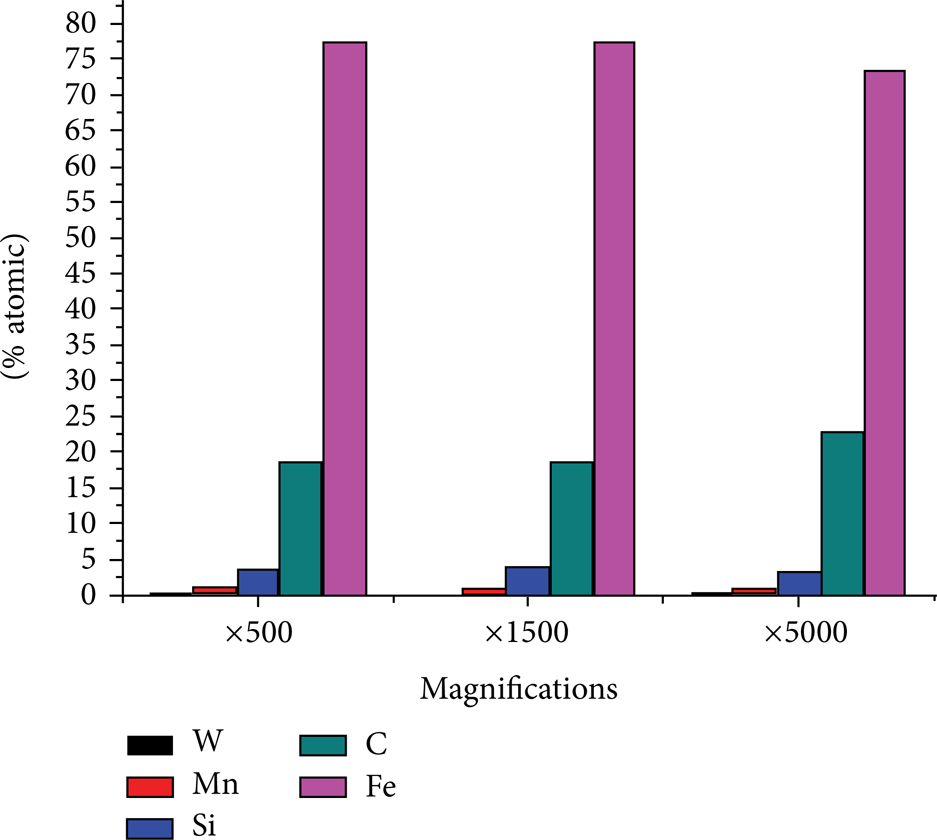
X-ray analysis in atomic percent of unused cylinder liner at magnifications × 500, × 1500, and × 5000.
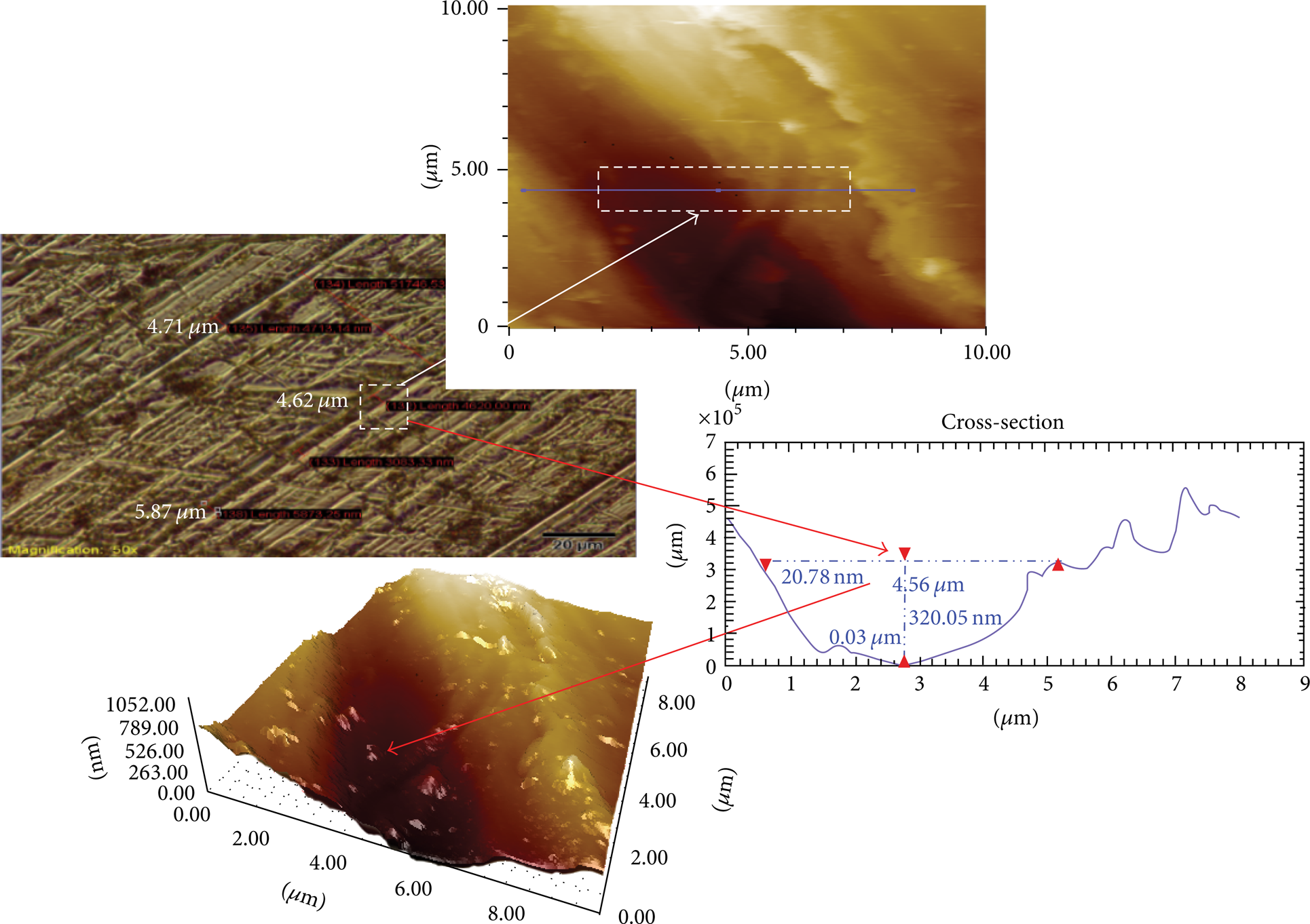
Optical and AFM images of honing marks and their dimensions of the new cylinder liner. (White arrow shows optical microscopy and AFM measurements of honing mark width and red arrows show depth and width measurements of same honing mark by AFM).
Figure 7 shows the new oil ring optical microscopy, SEM images, and X-ray spectra. It can be seen from X-ray spectra that unused oil ring surface contains calcium (Ca), phosphorus (P), and zinc (Zn) elements which are used as antiwear and detergant agents in lubricating oils.

Optical, SEM, and X-ray analysis of new oil control ring.
Figure 8 illustrates the X-ray elemental analysis results of unused zinc phosphate coated oil ring at three different magnifications. Higher levels of Ca, Zn, and P elements were detected on the new oil ring surface due to zinc phosphate coating and it can be seen that there are little differences between magnifications.

X-Ray analysis in atomic percent of the new oil ring at magnifications × 150, × 1500, and × 5000.
Figure 9(a) shows the contact area of the cylinder liner. The width of the contact area was 295.23 μm and the length was 1331.84 μm. Figure 9(b) illustrates red marked rectangle area of Figure 9(a). Two main wear scars parallel to sliding direction were detected in surface observations and their widths were 3.20 μm.

Optical image of the contact area at magnification x5 (a). Optical image of wear scars at magnification x50 (b).
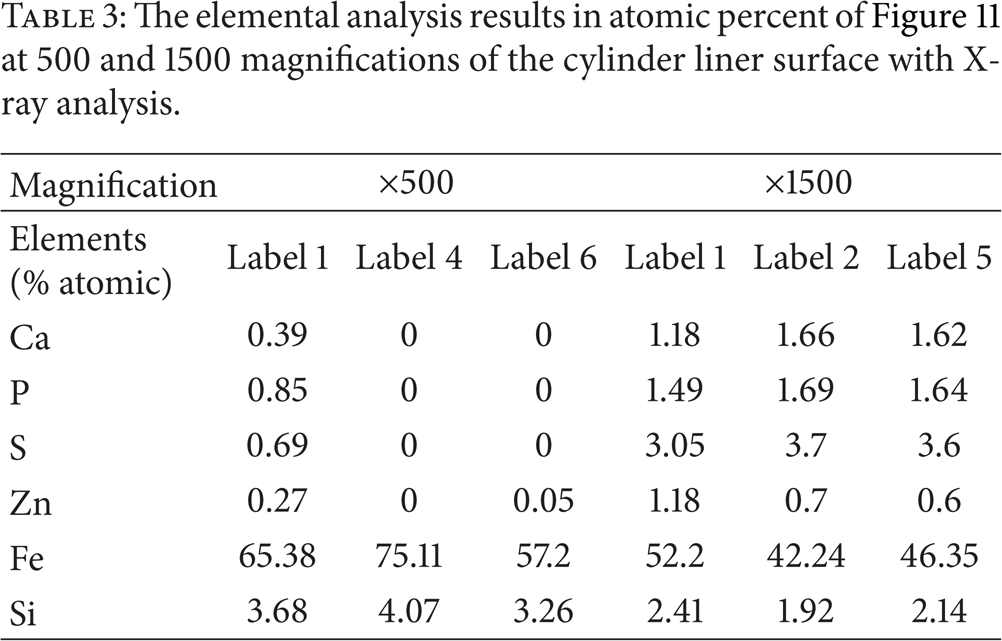
Figure 10 illustrates two areas on the cylinder liner surface to identify protective additive layer at different magnifications in SEM images. Figure 10(a) shows the elemental accumulation of additives on rubbed area of cylinder liner which was labeled as 1, 4, and 6 in X-ray spectra at magnification 500 of SEM image. It can be seen that the accumulation of Ca, P, and Zn was higher at label 1 and very low at labels 4 and 6. In these labeled areas (1, 4, and 6), very weak protective additive layers were formed. Figure 10(b) shows red rectangle marked area of Figure 10(a) at magnification 1500 where the stronger protective additive layers (darker irregular spotted areas) are formed. The elemental analysis of labels 1, 2, and 5 shows that this area was highly influenced by oil protective additive layers where higher levels of additive accumulation of Ca, Zn, S, and P were detected. Table 3 illustrates the elemental analysis results of Figure 10 in atomic percent at 500 and 1500 magnifications.
The elemental analysis results in atomic percent of Figure 11 at 500 and 1500 magnifications of the cylinder liner surface with X-ray analysis.

SEM image and X-ray analysis of elemental accumulation of additives on liner surface at magnification × 500 (a). SEM image and X-ray analysis of elemental accumulation of additives in red marked area on liner surface at magnification × 1500 (b).
AFM contact mode technique was applied to the samples for quantitative wear width and depth measurements. PointProbe Plus Contact (PPP-CONT) and silicon nitride (Si3N4) cantilever without coating (width = 46 μm, length = 452 μm, and nominal spring constant = 0.081 N/m) were used in AFM measurements. Scans were carried out in ambient conditions. Figure 11(a) illustrates an AFM image of the unworn area of the cylinder liner with protective oil additive layer and white pads on the image show higher level of additive accumulation of Ca, Zn, P, and S. Figure 11(b) shows an AFM image of the worn area that contains one of the wear scar which is illustrated in Figure 9(b) and measured wear scar width was 3.28 μm and the depth was 424.56 nm. The measured length of this wear scar by optical microscopy was 863.13 μm. The wear volume of this wear track was (0.00328 mm × 0.86315 mm × 0.00042456 mm) 1.202 × 10⁻⁶ mm³. It can be seen in Figure 11(b) that no elemental accumulation of additives was detected near the wear scar.

The AFM images of cylinder liner; scanned area with protective additive layer (a). Scanned area with no protective additive layer and detected wear scar (b).
Figure 12 shows the AFM image of the second wear scar of nonprotective additive layer area. The width of the wear scar was 3.18 μm and the depth was 482.15 nm. The length of this wear scar was 873.68 μm. The wear volume of this wear track was (0.00318 mm × 0.87368 mm × 0.00048215 mm) 1.34 × 10⁻⁶ mm³. Total wear volume of detected wear scars on cylinder liner surface was 2.542 × 10⁻⁶ mm³.

The AFM image and the dimensional measurement of the wear scar detected in Figure 11(b) in nonprotective additive layer area of cylinder liner.
Figure 13 shows the SEM image of the oil ring surface which was compared in two areas: worn (G3, marked with green) and unworn (G2, marked with red). Table 4 shows the results of X-ray analysis of Figure 13. As can be seen in X-ray spectra, the additive elements such as Ca, Zn, and P decreased and Fe, Si, and S elements increased in the worn area. This indicates that zinc phosphate coating was removed from the ring surface during reciprocating motion.
Detected elements on unworn (G2) and worn (G3) areas of the oil ring surface with X-ray analysis.


The SEM image and X-ray analysis of elemental accumulation of additives in worn and unworn areas of oil ring surface.
Figure 14 shows the AFM images of Figure 13 of unworn and worn areas. Figure 14(a) illustrates unworn area where the average surface roughness (R a ) was 1.12 μm. Figure 14(b) shows that the worn area where surface coating was removed and the average surface roughness was 0.154 μm.

AFM images and roughness (Ra) of oil ring: unworn area (a); worn area (b).
As illustrated in Figure 15(a) and Figure 15(b), two wear scars on the oil ring surface were detected by optical microscopy and SEM, which were approximately 2 μm in width. The AFM measurement of the white marked area in optical microscopy of the wear track is shown in Figure 15(c), where the width of wear track was 1.65 μm, the length was 440 μm, and the depth was 100.94 nm. Therefore, wear volume of this wear track was (0.00165 mm × 0.44 mm × 0.00010092 mm) 7.32 × 10⁻⁸ mm³. The second wear track which is on the left side of the first measured wear scar was 1.94 μm in width and 92.49 nm in depth. The wear volume of this second wear track is (0.00194 mm × 0.44 mm × 0.00009249 mm) 7.89 × 10⁻⁸ mm³. The total wear volume of ring was 15.21 × 10⁻⁸ mm³. The wear rates (w = Vtotal/F·L) for liner and ring were calculated by dividing the total wear volume to factoring the force (F = 100 N) and the total sliding distance (L = 30.24 m). The calculated wear rate for cylinder liner was 8.40 × 10⁻¹⁰ mm³/Nm and for zinc phosphate coated ring was 5.29 × 10⁻¹¹ mm³/Nm.

Optical image (a); SEM image of worn area of the oil ring surface (b); AFM image and measurement of the wear scar detected on the rubbed area (c).
4. Discussion
The functions of a piston ring are to seal off the combustion pressure for reducing the blow by, to distribute and control the lubricant, to transfer heat, and to stabilize the piston in internal combustion engines. Piston rings for modern internal combustion engines should meet all the requirements of a dynamic seal for linear motion that operates under demanding thermal and chemical conditions [14, 15]. Therefore, piston ring materials should be resistant to the operating conditions. Piston rings are manufactured from the cast iron or steel and are often surface-treated or coated [16, 17]. Under operation, thermal load, extreme pressure, and corrosive effects are the most important running parameters. To protect the rings surface from the effects of operation conditions especially from the corrosion, coating techniques have gained importance in the automotive industry. The main types of the corrosive protection coatings for rings are phosphate chemical conversion coatings, chromate chemical conversion coatings, and anodizing coatings. As Kennedy and coworkers indicated in their study, the piston ring coating is applied with a layer with thickness of 3 to 5 microns [18]. In general, phosphate chemical conversion coating is applied for oil control rings in internal combustion engines which is a conversion process where the surface of the casting is transformed by a chemical treatment of phosphoric acid into iron-containing phosphate crystals [19]. In this study, calcium which exists as an element in the additive composition of crankcase oil was detected on the zinc phosphate coated of the new oil control ring surface by X-ray spectroscopy measurements. The technical bulletin of HG Products explained that when the calcium modified zinc phosphate is applied as a coating material, it produces lighter, more adherent, tighter, and more uniform coatings than regular light zinc phosphates [20]. Nair explained the reason for using calcium as a phosphating additive by suggesting that calcium is a corrosion inhibitor and indicated that addition of calcium in zinc phosphating baths decrease the coating weight [21].
In this study, zinc, calcium, and phosphorus ratios were detected as 5.82%, 1.765%, and 6.135% on the new oil ring surface, respectively, before the experiments. At the end of the reciprocating test, the quantities of zinc, calcium, and phosphorus elements decreased to 1.08%, 0.89%, and 2.37% on the ring surface and higher elemental ratio of calcium, phosphorus, sulfur, and zinc (1.18%, 1.49%, 3.05%, and 1.18% in atomic percent, resp.) were found on the cylinder liner surface, originated from the lubricant and oil ring coating. This result shows that the coating material was removed from the ring surface and additive elements such as Ca, Zn, S, and P from the oil transferred and formed a protective layer on the cylinder liner surface. In contrast to other additives, detected sulphur additive on the ring and cylinder surfaces originating from lubricant was raised in the worn area of ring surface. Hivart et al. and Pokorny et al. showed in their research that the phosphate coatings do not exhibit intrinsic lubricating properties but can absorb and hold a considerable quantity of lubricant by virtue of their porosity [22, 23]. However, no porosity was detected in the present study after the surface observations. Pokorny et al. observed the surface morphology of the zinc phosphate, zinc-calcium phosphate, and manganese phosphate coated materials with SEM and they had measured average surface of zinc-calcium phosphate coating which was R a = 1.78 μm. Morina et al. used AFM to investigate the surface morphology and roughness changes by using a pin-on-reciprocating plate tribometer and the oils comprise combinations of base oil (PAO6), zinc dialkyldithiophosphate (ZDDP), and molybdenum dithiocarbamate (MoDTC) additives. They concluded that at least three scans they had collected on the same wear scar during the AFM measurements and they showed the morphology of large antiwear pads (white smooth patches) elongated in the sliding direction with dark strips. They also measured line roughness of test samples with AFM images [24]. Papadopoulos, Priest and Rainforth made surface analyses on the grey cast iron cylinder liner and chromium coated piston ring after reciprocating test and showed worn and unworn areas of the surfaces with optical and SEM images. They found that wear scars in the direction of sliding of a cylinder liner and cylinder liner-piston ring surfaces have become smoother due to wear after testing [25]. Rosén et al. examined an ordinary car engine grey cast iron cylinder liner surface with AFM and found that wear scar widths were smaller than 4 μm. They also calculated the honing mark heights below 0.49 μm. In the present study, similar AFM results were detected, where wear width and depth were 3.20 μm and 0.48 μm and the honing mark height was 0.320 μm [26]. Friction coefficients were measured during the experiments and the values of friction coefficients were approximately 0.11. Truhan et al. carried out friction tests with ring segment and prepared cast iron flat in tribotest rig and they foundthat friction coefficient was about 0.11 between 90 and 100°C lubricant temperature and at 100 N load [27]. Parallel to this, in Tomanik's study test results showed the usual boundary lubrication friction coefficient of ∼0.11 when lubricant condition approaches boundary regime [28]. In this study, the same friction coefficient was applied in boundary lubrication regime which is in the same condition with Truhan et al.'s and Tomanik's studies. It is interesting to find out that zinc phosphate coating removed on oil ring surface and contaminate with the lubricant during the friction process. This result raises two important questions as follows.
When the zinc phosphate coating is removed during the friction process and contaminate with the lubricant, does it have an antagonist effect on the additive composition of oil in an internal combustion engine?
If zinc phosphate coating is removed during the friction process in an internal combustion engine, why do ring manufacturers use this coating technique? Do they use this technique to extend the life of the oil ring as a spare part?
To find out the answers to these questions, zinc phosphate coated spheroidal graphite cast iron oil ring and uncoated spheroidal graphite cast iron oil ring will be tested in same reciprocating tribotest rig and in an internal combustion engine test bench.
5. Conclusions
The tribometer experiment in the study has focused on the tribological performance of the zinc phosphate coating in the light of surface analysis and surface layer protection of calcium-zinc phosphate coated oil control ring and cylinder liner with calcium, phosphorus, zinc, and sulphur containing lubricant in boundary lubrication regime. The following conclusions were drawn from the experimental results.
The unused oil control ring was coated with calcium modified zinc phosphate and the detected calcium elemental ratio on the ring surface is 1.66% (in atomic).
Zinc phosphate coating was removed during the friction process on the ring surface.
Calcium, zinc, and phosphorus elemental rates (1.11%, 2.88%, and 3.89% atomic percent, resp.) decreased on the oil control ring surface especially in worn area at the end of the test.
Higher levels of calcium, phosphorus, sulphur, and zinc elemental ratios (1.18%, 1.49%, 3.05%, and 1.18% in atomic percent, resp.) were detected on the cylinder liner surface due to elemental transfer from the ring surface and protective additive layer of lubricating oil.
Cylinder liner wear rate (8.40 × 10⁻¹⁰ mm³/Nm) was higher than the zinc phosphate coated ring (5.29 × 10⁻¹¹ mm³/Nm).
Footnotes
Abbreviations
Conflict of Interests
The authors declare that there is no conflict of interests regarding the publication of this paper.
Acknowledgments
The authors would like to thank the Lamcos Yves Berthier (Lamcos INSA Lyon, France) for providing and supporting the Tribometer Impact II, Dr. Hiroshi Fujita for the oil support from Idemitsu Kosan Co., Ltd., petrochemical company in Japan, and Dr. Oğuzhan Gürlü from Istanbul Technical University for supporting AFM in this work.