
Abstract
Some important information pertaining to blade fault is thought to be concealed in highly unsteady casing vibration. This paper explores suitable methods to best reconstruct blade related signals from raw casing vibration, which could be used for diagnosis of blade fault. The feasibility of translation invariant wavelet transform and cycle spinning (TIWT-CS) technique in reconstruction of these signals is investigated in this paper. Subsequently, a new parameter for blade fault diagnosis, namely, the energy profile of blade signal (EPBS), is formulated. Experimental results show that TIWT-CS method effectively retained blade related signals, while other unwanted signals such as system noises and aerodynamic induced vibration are reasonably suppressed. EPBS provides an indication of the condition of blade faults in rotor system, whereby the exact position and the quantity of faulty blades, as well as the root cause of blade fault, can be identified. In comparison, the energy profile plots using unfiltered casing vibration were found to be highly unstable and therefore provides inconsistent results for diagnosis of blade fault.
1. Introduction
Blade fault is one of the most destructive and elusive problems in power generation and aerospace industries. The most common types of blade fault include blade rubbing, low and high cycle fatigue failures, blade creep, fouled blade, loose blade, and blade induced foreign object damage (FOD). Undetected blade fault could further deteriorate to trigger some serious consequences such as in the event of FOD that could potentially undermine the functionality and total integrity of the machine. Traditionally, detection of blade fault is often conducted via spectrum analysis of bearing vibration. This method monitors changes in the vibration spectrum and in particular the amplitude of blade pass frequency (BPF) and its sidebands components. Any abnormal changes in the amplitudes of these frequencies together with the presence of some peculiar vibration peaks in the vibration spectrum could indicate the occurrence of blade fault. This method has been studied by Kubiak et al. [1] and Simmons ([2, 3] and Parge et al. [4] and Parge [5]), amongst others. In more recent years, the application of advanced signal analysis techniques such as wavelet analysis and artificial intelligence methods to detect blade fault has been reported. Angelakis et al. [6] applied neural networks technique to classify healthy and faulty blade condition based on experimental study. Peng et al. [7] used the reassigned wavelet scalograms to improve the detection of rubbing and found that the amplitude of vibration components at high frequencies increases in proportion to the severity of rubbing. The authors, Lim and Leong [8], had also explored a method to detect blade rub using operational deflection shape (ODS) of the rotor casing. However, most of these methods are found inadequate for detailed blade fault diagnosis purposes. For instance, they failed to provide detailed information regarding the physical configuration of blade fault and thus failed to reveal its root cause.
In this study, we hypothesize that a more detailed blade fault diagnosis method can be established if we can reconstruct vital blade signal from raw casing vibration in view of the close proximity between blades and rotor casing. However, raw and unfiltered casing vibration is known to be complex and highly volatile in nature (see Figure 1), of which could comprise many vibration components such as aerodynamics induced vibration, harmonics of operating frequency, blade pass frequency, blade fault signal (e.g., high frequency rubbing signal), and stochastic system noises. The objective of this study is therefore to investigate suitable signal denoising method to denoise and reconstruct the underlying blade signal from the raw casing vibration which is useable for more detailed blade fault diagnosis.

Two samples of raw casing vibration measured from an experimental rotor system. Unfiltered casing vibration is seen to be complex and highly volatile in nature.
This paper is organised in five sections. Section 1 provides the background of the this study. This is followed by the introduction on the wavelet-based denoising and signal reconstruction in Section 2. Specific details on translation invariant wavelet transform and cycle spinning (TIWT-CS) technique to denoise and reconstruct blade signal are also given in this section. Section 3 describes the methodology and the details of the experimental study. Section 4 discusses the experimental results and provides the summary of findings achieved in this study. Lastly, the overall conclusion of this study is given in Section 5.
2. Wavelet Denoising and Signal Reconstruction
The main objective of any denoising algorithm is to find the best estimation of ○(n) of the underlying true signal x(n) by eliminating additive noises, d(n), which present in the noisy signal, y(n):

One of the most common denoising methods is the Fourier-based denoising algorithm. This method assumes that the underlying true signal is mainly present at low frequency region and therefore by passing the noisy signal through a low-pass filter; this will automatically eliminate high frequency noises in the noisy signal. However, this method may not be suitable for machinery fault diagnosis application. The reason is that by running the noisy signal through a low-pass filter, it will not only eliminate high frequency system noise but also wipe out all other high frequency signal related to machinery fault (e.g., blade rub) that are located in the same frequency band. For machinery fault diagnosis, denoising of signal has to be carried out more selectively of which the simple band-pass filter can no longer fulfill the need. In view of these requirements, multiresolution wavelet denoising method is proposed and investigated for the reconstruction of blade signal from raw casing vibration. In this study, the blade signal that could be recovered from raw casing vibration should possess the following characteristics.
It is free from random system noises.
All important blade related signals that coincide with system noise such as blade rub signal will be retained.
The instantaneous fluctuation of blade pass frequency signal will also be well preserved.
Signals related to rotor dynamics (e.g., harmonics of operating speed) and aerodynamics (e.g., flow induced vibration) will be suppressed intentionally in order to minimise the influence of these signals from affecting blade faults diagnosis results even though these signals are generally not considered as noises.
Essentially, wavelet analysis computes the similarity between the signal and the wavelet function at specific time and scale (frequency subband). A larger wavelet coefficient represents a very strong and important signal at particular subband frequency. In contrast, small wavelet coefficient represents either the trivial details of signal or the system noise and therefore can be eliminated. Let one denote the wavelet transform of noisy signal as

where W denotes the wavelet transform operator. Therefore, the estimation of underlying true signal, ○(n), is simply an inverse wavelet transform of the thresholded wavelet coefficients, where T denotes the thresholding operator:

In short, the basic idea of wavelet-based denoising is to perform thresholding operation on the wavelet coefficients before reconstructing the remaining wavelet coefficients back to time domain via inverse wavelet transform as illustrated in Figure 2.
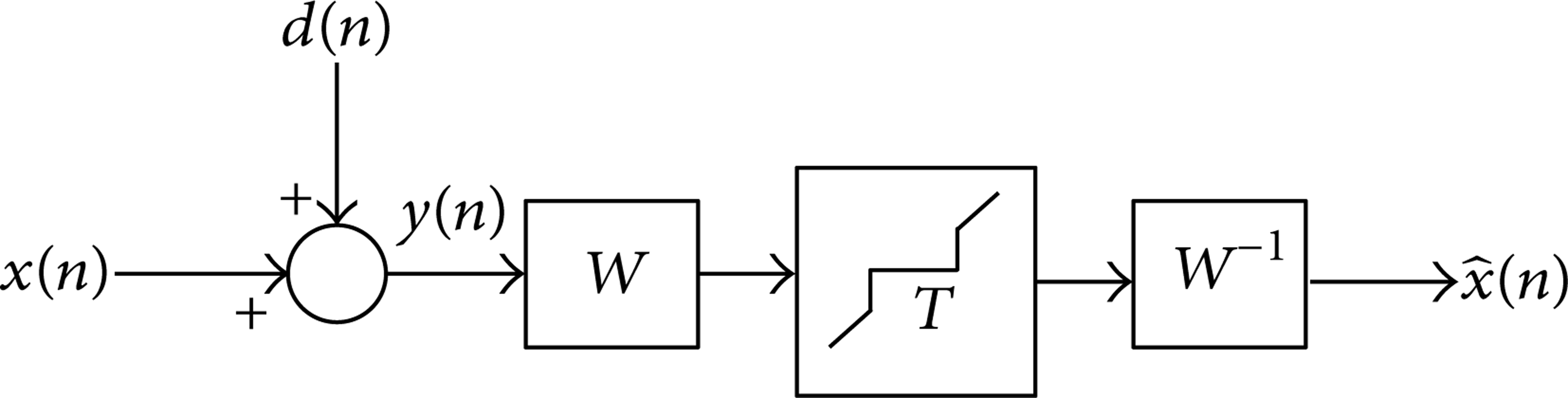
Block diagram depicting the basic idea of wavelet denoising.
2.1. Translation Invariant Wavelet Transform (TIWT)
TIWT is a type of wavelet transform which is almost similar to the algorithm of discrete wavelet transform (DWT). In classical DWT, the process of down sampling or decimation is performed after each level of wavelet decomposition. The decimation process retains only the even indexed elements of the wavelet coefficients. This is done mainly to reduce by half the signal length for each level of decomposition and thus improves the computational efficiency (see Figure 3(a)). As a result, the signal is shifted in time, rendering DWT a translation variant process. In other words, the reconstructed signals of the original signal would be different from the reconstructed signal of the shifted version of the original signal. In order to overcome the translation variant problem of DWT, TIWT denoising algorithm was proposed by Coifman and Donoho [9]. Essentially, TIWT does not decimate any wavelet coefficients for each level of decomposition. Instead, upsampling process is applied by inserting zeros between the filter coefficients to make the signal exactly the same size as the original signal for every level of decomposition (see Figure 3(b)). TIWT is therefore a redundant scheme as the output of each level of decomposition contains the same number of samples as the input but only at half the signal resolution (see Figure 3(b)). It is this characteristic of TIWT that makes it a translation invariant process, which can be exploited to improve its capability in signal denoising.

A comparison of (a) DWT and (b) TIWT. In DWT, an original signal will pass through a pair of low-pass and high-pass wavelet filters followed by downsampling, resulting in decomposed signals having a length shortened by half after each level of decomposition. In TIWT, as downsampling process is not applied for each level of decomposition, which results in equal signal length for every level of decomposition.
2.2. Thresholding of Wavelet Coefficients
One of the most important step in wavelet denoising is to determine the optimum threshold value. If a threshold value is set too large, it will cause some of the important features in the signal to be overly suppressed or even eliminated. In contrast, if the threshold value is set too small, some important features of a signal will still be concealed in the noisy signal. In general, two different methods of threshold value estimation could be employed, namely, the universal threshold estimation and the level-dependent threshold estimation. Universal threshold estimation computes the optimum threshold value based on the noise variance and the length of the signal. The computed threshold value is then uniformly applied on all wavelet coefficients. Universal threshold value T is given by (4), whereby σ and N represent the estimation of noise variance and the length of the signal, respectively.
Consider

In comparison, Stein's unbiased risk estimation (SURE) is an adaptive level-dependent threshold estimator proposed by Donoho and Johnstone [10]. The SURE threshold values are computed based on the minimum risk associated with a particular threshold value and is given by
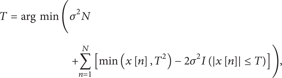
where x[n] is the original signal and I is the indicator function of which its value is determined as I = 1 if |x[n]| ≤ T and I = 0, otherwise. Heuristic SURE is another type of threshold value estimation as proposed by Donoho. Essentially, this method is the hybrid of universal threshold estimation and SURE estimation. The optimum threshold values of heuristic SURE are decided based on the significance test of the two. As a result, if the signal-to-noise ratio is very small, the universal threshold value is adopted. Otherwise, SURE threshold values will be adopted for each level of signal decomposition. In this study, heuristic SURE threshold estimation is used to determine the optimum threshold value of the signal automatically.
After having determined the optimum threshold value, thresholding process is carried out by following certain rules of thresholding. The simplest rules of wavelet thresholding are known as hard and soft thresholding rule and are given by (6) and (7), respectively.
Consider


In short, hard thresholding nullifies all wavelet coefficients which are smaller than the threshold value, leaving the larger one unchanged. For soft thresholding, besides being able to nullify all coefficients that are smaller than threshold value, it also scales down the remaining coefficients to achieve continuous distribution of the wavelet coefficients. In this study, soft thresholding rule was adopted as it produces smoother reconstructed blade signal in our application.
2.3. Signal Reconstruction via Inverse TIWT and Cycle Spinning
Cycle spinning technique as proposed by Donoho [11] makes use of the periodical translation invariant nature of TIWT to enhance its denoising capability. Without cycle spinning technique, some remaining noises may still be present in the reconstructed signal. The basic idea of cycle spinning technique is that the remaining noises can be systematically reduced by linearly averaging multiple set of the reconstructed signals produced from a single noisy signal. Essentially, TIWT and cycle spinning technique (TIWT-CS) enables multiple set of the reconstructed signals to be obtained based on one noisy signal by periodically shifting the signal one at a time. Each periodically shifted signal is then separately transformed, thresholded, inversed, and then shifted back to obtain the individual estimate of the reconstructed signal. The multiple reconstructed signals are then linearly averaged to obtain the final estimation of signal as illustrated in Figure 4.
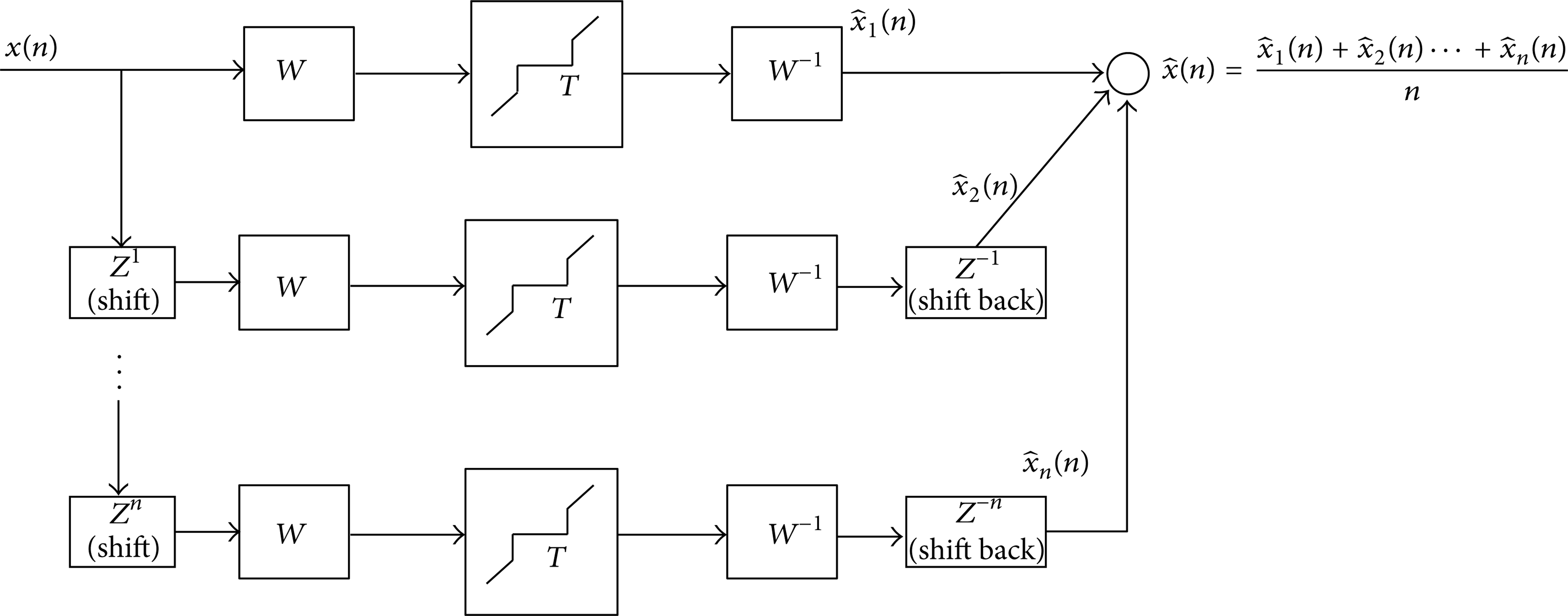
The concept of TIWT and cycle spinning technique for systematic signal denoising. Each periodically time shifted signal is separately transformed, thresholded, inversed, and shifted back to obtain the individual reconstruction of signal. Subsequently, multiple sets of reconstructed signals are then linearly averaged to obtain the final reconstructed signal.
2.4. Overall Signal Analysis Scheme
In this study, the raw casing vibration of one cycle of rotation was extracted from continuous vibration measurement. TIWT (coiflet 5) is then applied onto the extracted signal, started from decomposition level 1 to 8. Subsequently, heuristic SURE method was applied to determine the optimum threshold value of the signal automatically. Prior to performing thresholding operation based on soft thresholding rule, wavelet coefficients at level 6 to 8 (which contain mostly the harmonics of operating speed) were deliberately suppressed by increasing the threshold value of these scales by twofold. This is done to reduce the influence of these frequency components from affecting the results of blade fault diagnosis. Subsequently, inverse TIWT was then performed to reconstruct blade signal from raw casing vibration. After that, cycle spinning technique was applied onto the raw casing vibration signal of which the original casing signal was periodically shifted, one position at a time. The shifted signal then undergoes similar denoising sequence and processes (e.g., TIWT, thresholded, and inverse TIWT) before finally being shifted back to the original position. The series of reconstructed blade signals were then linearly averaged to yield the final estimation of the reconstructed blade signal. Thereafter, the reconstructed blade signal was then further divided into 12 segments to represent the vibration signal associated to the twelve number of blades in the test rotor. The root mean square (RMS) value of each signal segment was then to be calculated. The combination of RMS values represents the energy profile of blade signal (EPBS) plotted in polar representation format.
3. Experimental Study
An experimental study was conducted to simulate two typical blade fault conditions that occurred in turbomachinery, namely, creep induced blade rubbing (hereafter known as creep rub) and rotor eccentricity induced blade rubbing (hereafter known as stage rub) (see Figure 5). An experimental rig that consists of a rotor and casing, twelve number of blades, and experimental control mechanisms was designed and fabricated as illustrated in Figure 6. The mechanical parameters that were controlled in this study include blade length (to simulate creep), blade tip clearance (to simulate rotor eccentricity), and rubbing severity. Various lengths of blades were fabricated to represent normal blades (153 mm) and creep blade (155 mm and 157 mm). The initial blade tip clearance (measured from blade tip to inner surface of casing) was designed to be 7 mm. In order to examine the vibration response of creep blade, the healthy blade was replaced with a longer blade of various intended lengths. In order to simulate creep rub condition, a component termed as “top-head” made of aluminum sheet metal was installed onto the tip of the blade to extend the blade length and to act as the rubbing medium between the blade and casing. In this study, two conditions of creep rub were created, namely, single blade rub induced at blade number 7 (hereafter denoted as B7) and double blades rub induced at blade number 8 and 9 (hereafter denoted as B8 and 9).

Typical types of blade rubbing that occur in rotating machinery: (a) creep rubbing; (b) eccentric rubbing.
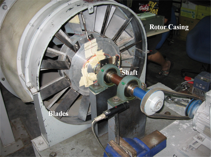
Experimental rig to simulate blade fault conditions.
Meanwhile, rotor eccentricity condition (also known as impending stage rub) was simulated in the experiment by gradually reducing the blade tip clearance. This was done by removing tiny pieces of sheet metal each with 1 mm thickness that placed between the upper and lower casing. In the experiment, the initial blade tip clearance of 7 mm was reduced to 2 mm to represent condition of rotor eccentricity. Subsequently, the condition of stage rubbing was created by fitting top-head onto each and every blade in order to rub against casing. All vibration signals in the experiment were measured during steady state (1500 rpm) using accelerometers placed at the upper casing.
4. Experimental Results and Discussion
4.1. Comparison of Reconstructed Blade Signal and Raw Casing Vibration
A comparison between the reconstructed blade signal and raw casing vibration for all experimental conditions is illustrated in Figure 7. From Figures 7(a) and 7(b), the reconstructed blade signal of baseline conditions was seen to be relatively smooth as compared to raw casing vibration. The TIWT-CS algorithm has greatly reduced the spikiness of raw casing vibration caused by stochastic system noises and unsteady aerodynamics induced vibration. Under close examination, the fluctuation of twelve number of blade pass frequency signal can be seen. In contrast, the highly unsteady casing vibration has caused the blade pass frequency signal to be smeared. For rotor eccentricity condition (see Figure 7(c)), as the air gap between blade tip and casing had reduced, the raw casing vibration is seen to be more intense due to the increased pressure in the interior of the casing. In comparison, the reconstructed blade signal of rotor eccentricity condition is observed to be relatively smooth. The instantaneous fluctuation of blade pass frequency signal can also be seen with the amplitude range about 1.5 × of the baseline condition. For both creep rubbing conditions (B7 and B8 and 9), the vibration characteristics of casing vibration have changed significantly. In these cases, the reconstructed blade signals are found to be mostly the high frequency rubbing signals, while effects due to operating frequency and system noises are minimised. The amplitude range of these signals have increased from 2 mm/s (baseline condition) to about 10 mm/s for single blade rub B7 and 15 mm/s for double blade rub B8 and 9, respectively. For stage rubbing, significant increase in casing vibration is evident due to continuous rubbing impact exerted by every rubbing blade onto the casing. The amplitude range of this signal has increased exponentially to about 40 mm/s, which is about 20 × of baseline condition. Likewise, high frequency rubbing signal is well preserved in the reconstructed blade signal, of which only some extremely high peaks in time waveform are being normalised.

Comparison of reconstructed blade signal and unfiltered raw casing vibration for all experimental conditions. (a) Baseline number 1, (b) baseline number 2 (c) rotor eccentricity, (d) single creep rub B7, (e) double creep rub B8 and 9, (f) stage rub.
4.2. Comparison of EPBS and Energy Profile of Raw Casing Vibration
The comparison of EPBS and energy profile of raw casing vibration for baseline and creep rubbing conditions is illustrated in Figure 8. The EPBS of baseline condition is seen to be fairly consistent and circular in shape with only minor amplitude fluctuation around 0.6 mm/s being observed. In comparison, the energy profile of raw casing vibration is seen to be highly unsteady and uneven in shape. Therefore, blade fault diagnosis using the energy profile of raw casing vibration is difficult as it is adversely affected by the presence of unwanted signals such as flow induced vibration and random system noises. Subsequently, EPBS of creep rubbing and baseline condition are compared. The EPBS shape of creep rubbing conditions is significantly different from the baseline condition. The considerably inflated and skewed shape of EPBS for creep rubbing conditions indicate that the vibration energy has increased significantly due to blade rubbing. In addition, EPBS shape of single creep rub B7 and double creep rub B8&9 are found to be distorted with energy surge coincided with the position of rubbed blade in rotor. This indicates that analysis on the shape of EPBS could be used to estimate the positions as well as the number of rubbed blade that occurred in the rotor, which is generally unattainable based on conventional vibration analysis method. In contrast, the energy profile of raw casing vibration for both creep rubbing conditions is observed to be highly unsteady and chaotic (especially for creep rub B7 condition) and therefore blade fault diagnosis based on this method could result in misdiagnosis due to the influence of unwanted signals.

Comparison of (a) EPBS and (b) energy profile of raw casing vibration for baseline and creep rub conditions.
Figure 9 compares the EPBS and energy profile of raw casing vibration (in logarithm scale) for rotor eccentricity induced faults. At a glance, the energy profile of raw casing vibration for both baseline and rotor eccentricity are seen highly unsteady and overlapping. It is difficult to differentiate between them based on the shape of its energy profiles. In comparison, EPBS of rotor eccentricity is fairly consistent and circular in shape. The uniformly increase in EPBS shape of rotor eccentricity condition indicates a total increase in vibration energy due to increased air pressure. This enables it to be differentiated from the baseline condition. For stage rubbing, an enormous and collectively surge in vibration energy of both EPBS and energy profile of raw casing vibration can therefore provides evidence about the occurrence of massive stage rubbing.

Comparison of (a) EPBS and (b) energy profile of raw casing vibration for baseline, rotor eccentricity, and stage rub.
4.3. Summary of Findings
This study demonstrated the viability of using the reconstructed blade signal from raw casing vibration for more detailed blade fault diagnosis. Experimental results show that the underlying blade signal can be reconstructed based on TIWT-CS algorithm. TIWT-CS algorithm enables important features associated with blade fault such as the instantaneous fluctuation of blade pass frequency signal and blade rubbing signal to be reconstructed while selectively suppresses any unwanted effects due to aerodynamics, rotor dynamics, and random system noises.
By analysing the shape and magnitudes of EPBS, the severity as well as the root cause of the blade fault could be identified. For instance, an enormous and uniformly increase in the shape of EPBS could indicate the occurrence of stage rubbing, while a skewed EPBS indicates the occurrence of creep rubbing. This information provides useful insight to plant personnel on the subsequent corrective measures that required during maintenance works.
The merit of EPBS in diagnosis of blade fault is evident especially for differentiating rotor eccentricity from baseline condition as well as revealing the physical configuration of blade faults in creep rubbing. EPBS thus provides a simple and effective mean for more detailed blade fault diagnosis.
5. Conclusions
The feasibility of TIWT-CS to reconstruct blade signal from highly unsteady casing vibration is investigated in this paper. This method is found to be able to reveal subtle changes in blade signal due to blade fault. Subsequently, EPBS is formulated based on the reconstructed blade signal. Experimental results show that the analysis of shape and magnitude of EPBS can be used to detect the severity as well as to identify the root cause of the blade fault. Beside this, EPBS is also found to be able to provide more information on the physical configuration of blade fault such as the quantity and the exact position of faulty blades in rotor as compared to the energy profiles generated from raw casing vibration.
Conflict of Interests
The authors declare that there is no conflict of interests regarding the publication of this paper.
Footnotes
Acknowledgment
This work is supported by Exploratory Research Grant Scheme (ERGS) (R.K130000.7840.4L089) as financed by the Ministry of Education Malaysia.