
Abstract
Direct inkjet printing is a versatile additive manufacturing technology to produce complex three-dimensional components from ceramic suspensions. By successive printing of cross-sections, the sample is built up layer by layer. The aim of this paper is to show the different possibilities of direct inkjet printing of ceramic suspensions, like printing of oxide (3Y-TZP, Al2O3, and ZTA) or nonoxide (Si3N4, MoSi2) ceramics, featuring microstructures, laminates, three-dimensional specimens, and dispersion ceramics. A modified thermal inkjet printer was used and the ink replaced by aqueous ceramic suspensions of high solids content. The suspensions were processed in an attrition mill or agitator bead mill to reduce the grain size <1 μm to avoid clogging of printhead nozzles. Further significant parameters are rheological properties (viscosity and surface tension) and solids content which were adjusted to the requirements of the printheads. The printed and sintered samples were analysed by SEM. Mechanical properties of 3Y-TZP samples were examined as well by use of the ball-on-three-balls test. The biaxial flexural strength of 3Y-TZP specimens was up to 1393 MPa with a Weibull modulus of 10.4 for small specimens (3 × 4×0.3 mm3).
1. Introduction
Additive manufacturing (also known as freeform fabrication or generative manufacturing) comprises a group of technologies that feature construction of objects from 3D model data by assembly of materials, typically layer by layer [1]. By these means complex three-dimensional ceramic components can be produced directly without the need for moulds or part-specific tools. Depending on the technology the shape of the sample is realized by consolidating a powder bed either by addition of a binder (three-dimensional printing [2–4]), or by selective heat treatment (e.g., selective laser sintering or selective laser melting [5–8]), or by selective curing of a photosensitive resin containing ceramic particles (stereolithography [9–12]), or by direct deposition of material (e.g., fused deposition modelling [13, 14], 3D printing in filamentary form [15, 16], aerosol jet printing [17], or direct inkjet printing [15]).
Following ASTM F2792-12a, direct inkjet printing (DIP) is considered a form of 3D printing as the construction of a specimen is realized by material deposition through a nozzle of a printhead [1]. In contrast to classical 3D printing where a bonding agent is deposited in a powder bed (binder jetting), the emitted droplets in DIP contain the building material which is selectively deposited on a substrate (material jetting) [1]. The latter enables additive manufacturing of layers and (micro) structures as well as complex three-dimensional geometries from ceramic suspensions with high solids content. The selective deposition of single particle-loaded droplets permits high precision whose level of detail even allows accurate placement of different materials next to each other. Furthermore, the resulting structures printed by DIP feature high density and mechanical properties similar to conventionally fabricated ceramic components. Due to direct deposition of materials from suspensions, it is possible to produce multimaterial parts or even cavities which are not feasible in such form through other fabrication technologies. Additionally, the drop-wise use of varying materials makes it possible to specifically introduce internal stresses even in complex geometries.
In drop-on-demand inkjet printing a distinction is made between piezoelectric and thermal printheads. While both employ a pressure pulse to form drops, the method varies: the former ensures displacement of ink within the printhead chamber and drop ejection through deformation of a piezoelectric crystal thus mechanically creating a pressure pulse, while thermal printheads (also called bubble-jet) force ink through the nozzle by generating a bubble caused in the ink by a rapidly heated resistor [18, 19]. Thermal printheads were used for the studies shown in this paper.
The ceramic suspension used as ink in DIP consists of a suspension comprised of ceramic particles, dispersant, and functional additives, that is, surfactant, binder, and humectant. Depending on the specific requirements of the utilized printhead these ensure the necessary adjustment of rheological suspension properties like viscosity and surface tension. A further prerequisite for the ink development results from the nozzle diameter. As picolitre sized droplets are ejected through the fine nozzles of the printhead, the particle size needs to be controlled to prevent clogging of nozzles. Lejeune et al. [20] and Magdassi [18] have recommended the ratio of nozzle diameter to particle size to be larger than 50 or 100, respectively. Furthermore, for efficient and defect-free build-up on the one side and stabilization of dispersed particles against agglomeration, flocculation, and subsequent sedimentation on the other side high solids content (>20 vol%) is recommended [21].
Oxidic high-performance ceramics, in particular alumina (Al2O3) and yttrium stabilized zirconia (3Y-TZP), are distinguished by high flexural strength, wear resistance, and fracture toughness as well as confirmed biocompatibility. Based on these characteristics they have been used for many years in the field of endoprosthetics, for example, as hip joint ball or as matrix material for dental prosthesis like crowns and frameworks [22]. In recent years, zirconia has even been used for dental implants [23, 24]. The steadily rising demand for ceramic materials is due to aesthetic aspects and frequently occurring biological reactions, inflicted by application of metallic implants. Metallic hip joint parts (ball and acetabulum made of titan- or cobalt-chrome-alloys) may cause friction at the metal/metal pairing, generating undesirable biological reactions, for example, local and systemic metal intoxications.
Alumina and zirconia are bioinert; that is, after the implantation, no chemical or biological interactions between implant and surrounding tissue take place. Based on clinical studies it becomes more and more apparent that loosening of zirconia dental implants consistently takes place, like it has been observed in the early 1990s on monolithic alumina hip joint acetabula [25, 26]. The occurring loosening can be explained by the inert behaviour of the ceramic surface and the insufficient stimulation of the bordering bone tissue [25, 26]. For an enhancement of the cell adhesion and differentiation strategies for bioactivation have to be located. As the microstructure of a material significantly influences the biologic reaction at the interface [27–29], it is reasonable to change the microstructure of a surface in such a way that the cells could respond favourably with a change into osteoblasts (bone-building cells) to enhance the bone engraftment. Since no literature has been found to confirm response of cells to surface modification alone of alumina or zirconia further research has to be done to verify this thesis. With a high resolution printhead potential microstructures for this field of research could be produced by DIP.
Functionally graded materials (FGMs) are combinations of two or more different materials with a continuously varying distribution across the geometry of a part. In contrast to conventional composites FGMs are characterized by very smooth transitions between different materials, which substantially improve material properties or open up entirely new applications [32]. However, conventional forming technologies as slip casting or pressing are limited concerning their possibility to define and control such gradient material transitions [33]. In contrast DIP permits precise, accurate placement of single picolitre sized droplets and is thus eminently suitable to realize complex shaped geometries with functional material gradation.
The aim of this paper is to show the different possibilities of direct inkjet printing of ceramic suspensions, like printing of oxide or nonoxide ceramics, featuring microstructures, laminates, three-dimensional specimens, and dispersion ceramics. Ceramic suspensions are characterized regarding their particle size distribution, rheological properties (viscosity and dynamic surface tension), and solids content. The printed and sintered samples are analysed by SEM.
This paper provides an overview on work concerning direct inkjet printing originated at the Institute of Mineral Engineering of RWTH Aachen University. This concerns recapitulation of previously published work (on Si3N4, MoSi2, complex shaped structures of zirconia, and three-dimensional zirconia specimens for ball-on-three-balls test) as well as innovative novel experimental work (regarding microstructures, laminates, and dispersion ceramics).
2. Materials and Methods
A modified office type drop-on-demand thermal inkjet printer (HP DeskJet 930c, Hewlett Packard, Palo Alto, USA) was used for all samples unless stated otherwise. The modifications allowed layerwise build-up of parts from cross-sections. The printed layers were subsequently dried and the substrate lowered owing to the installation of a z-axis thus ensuring a consistent distance between the printhead and the substrate or the uppermost layer. Figure 1 shows a schematic of the printing system. This printer uses thermal printheads, of which only the black ink cartridge (HP51645A) was used to eject the ceramic suspensions. After draining and rinsing the cartridges, they were completely dried to prevent dilution with residual water. Subsequently they were refilled with a minimum of 25 mL of ceramic suspension and the remaining air was evacuated. The printhead provides 600 dpi spatial resolution by use of 304 nozzles with ∼30 μm nozzle diameter each.
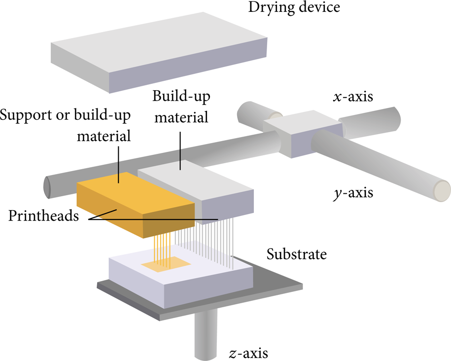
Schematic of the printing system (after [30]).
2.1. Materials Printed
2.1.1. Oxide Ceramics
Zirconia and alumina inks were prepared for DIP. The aqueous zirconia starting suspension had 40 vol% of solids content of 3Y-TZP (TZ-3YS-E, Tosoh, Tokyo, Japan) and 4 vol% of dispersant (Dolapix CE64, Zschimmer & Schwarz GmbH & Co. KG, Lahnstein, Germany). To prepare the suspension the submicrometer-sized 3Y-TZP powder with a specific surface area of (7 ± 2) m2/g, a mean particle size of 0.6 μm and a sintered density of 6.05 g/cm3 [39] were attrition-milled (30 min, 1200 rpm) in aqueous media using 1 mm zirconia beads [31]. For the alumina starting suspension an alumina powder (CT 3000 LS SG, Almatis, Ludwigshafen, Germany) with a specific surface area of 7.8 m2/g, a mean particle size of 0.5 μm, and a sintered density of 3.95 g/cm3 was dispersed in distilled water with dispersant Dolapix CE64 and milled using a laboratory agitator bead mill (MicroCer, Netzsch-Feinmahltechnik GmbH, Selb, Germany) with zirconia grinding beads (diameter 0.2–0.3 mm). These basic zirconia and alumina suspensions were diluted in order to achieve ceramic inks with final solids content of 27 vol% [21, 34, 36] and 31.1 vol%, respectively (Table 1). Further organic additives like humectants (Glycerol 85%, Hedinger, Stuttgart, Germany) and drying accelerators (Ethanol, Merck KGaA, Darmstadt, Germany) were added to increase the compatibility with the chosen thermal printhead [21, 30, 35, 39].
Zirconia (3Y-TZP) and alumina ink composition [30].

In order to print complex shaped structures of zirconia with enclosures and/or undercuts a supportive carbon based suspension was developed. This supportive ink was an aqueous dispersion of submicrometer sized, thermal type carbon black particles (Arosperse 15, Evonik Chemicals, Essen, Germany) with an average particle size of 0.28 μm. An alkali free carboxylic acid ester based dispersant was used (Dolapix ET85, Zschimmer & Schwarz GmbH & Co. KG, Lahnstein, Germany). The suspension was ball-milled for 36 h using Al2O3 beads of 5 mm diameter prior to jetting [36].
The 3Y-TZP and alumina ink as well as a pigment based reference ink (HP45) were characterized at 20°C in terms of particle size distribution, viscosity, and surface tension. The density of the 3Y-TZP ink was determined using a pycnometer (25 mL, Brand, Wertheim, Germany). The particle size distribution was measured according to the full Mie theory using the low-angle laser light scattering method (Mastersizer 2000, Malvern Instruments, Malvern, UK). Furthermore, the viscosity was determined at a shear rate of 1000/s using a rotational rheometer (Viscolab LC10, Physica, Germany) with a double gap concentric measuring system. The surface tension was analyzed according to the bubble pressure method (Proline t15, SITA Messtechnik, Dresden, Germany) for a bubble lifetime of 0.5 s [21, 34].
Printing of aqueous oxide ceramic suspensions was carried out by layerwise deposition using a modified drop-on-demand inkjet printer as described above. Printed structures contained single drops for printability evaluation [21], channel structures [30, 35], bridge frameworks [36], dental crowns [39], and molar teeth [40]. Furthermore test specimens with defined dimensions were produced to measure mechanical properties like characteristic strength, Weibull modulus, and fracture toughness.
Before sintering the printed components were first dried at 80°C for 6–12 h. The organic residue was pyrolized at 550°C for 3 h and the parts were manually removed from the substrate. Subsequently they were sintered in a powder bed at 1450°C for 2.5 h. [30, 34, 39, 41].
To determine the density of the sintered samples the principle of Archimedes with distilled water as immersion liquid was used, while green density was calculated by measuring volume and weight. A ball-on-three-balls test was carried out using a universal testing machine (Zwick Z010, Zwick/Roell, Ulm, Germany) with a jig especially designed at ISFK (Leoben, Austria) on two sets of rectangular shaped specimens (3 × 4 × 0.3 mm³ and 2 × 2 × 0.3 mm³) [42–44]. Fracture toughness was determined for 3 × 6 × 30 mm³ specimens by a four-point-bending unit (type 1186, Instron, Darmstadt, Germany) [30]. The characteristic strength σ0 and Weibull modulus m were calculated with a specific software (PEST/CARES, NASA, Cleveland, Ohio, USA) [45] using the maximum-likelihood method [46]. The microstructure of sintered parts was characterized by SEM (Leo 440i, Leo Elektronenmikroskopie GmbH, Oberkochen, Germany) and TEM (Philips CM30, Royal Philips N.V., Eindhoven, Netherlands).
2.1.2. Nonoxide Ceramics
As examples of nonoxide ceramics silicon nitride (Si3N4) and molybdenum disilicide (MoSi2) were used to realize structural and functional parts by DIP. The basis of the aqueous suspensions was α-Si3N4 powder (SN-E10, UBE Industries, Tokyo, Japan) with a specific surface area of 10 m2/g and a mean particle size of 0.5 μm and MoSi2-powder (Grade C, H. C. Starck GmbH, Goslar, Germany) with a specific surface area of 1.5 m2/g and a mean particle size of 2.8 μm. To allow liquid phase sintering of Si3N4, yttrium aluminum garnet (YAG, Treibacher Industrie AG, Althofen, Austria) was used as sintering additive. Si3N4 and MoSi2 were separately dispersed in aqueous media and ball-milled, using a laboratory agitator bead mill with ZrO2 grinding beads as mentioned above. This was necessary to meet the requirements of the printheads regarding particle size as described above. Solids content of the Si3N4- and MoSi2-suspensions was 30.2 and 26.7 vol%, respectively. After ball milling, the suspensions were stabilized and adjusted to the required physical and rheological ink properties of the printhead. The detailed ink composition and procedure were described elsewhere [37, 38].
Layerwise printing of aqueous nonoxide ceramic suspensions was carried out using the modified drop-on-demand inkjet printer described above. Printed structures contained pillar arrays and gearwheels of Si3N4 as well as MoSi2 heating elements. Furthermore, bulk parts with defined dimensions were realized to evaluate mechanical properties (characteristic strength, Weibull modulus, fracture toughness, and hardness).
After printing the green bodies were submitted to a debinding process. Si3N4 specimens were treated in air for 2 hours at 600°C while MoSi2 was debinded for 2 hours at 600°C in argon atmosphere to prevent oxidation. Si3N4 was pressureless sintered in a resistance heated furnace (HPW 250, FCT, Rauenstein, Germany) for 2 hours at 1780°C under flowing nitrogen. To avoid decomposition of the Si3N4 parts they were sintered in a powder bed consisting of Si3N4, sintering additives, and boron nitride. MoSi2 samples were fired for 15 minutes at 1700°C under flowing argon.
The microstructure of green and sintered parts was characterized by SEM. The density of the sintered samples was determined using the principle of Archimedes with distilled water as immersion liquid, while green density was calculated by determining volume and weight. Hardness was determined by use of Vickers indentation with an indenter load of 19.8 N and a dwelling time of 10 s. Fracture toughness (KIc) was calculated from median cracks emerging from the Vickers imprint according to the ICL method [47]. The strength analysis was performed on disc-shaped specimens (thickness (3 ± 0.05) mm, diameter (12 ± 0.1) mm) using the ball-on-three-balls (B3B) test [42–44]. The B3B test was performed with a universal testing machine (type 1186, Instron, Darmstadt, Germany). The characteristic strength σ0 and Weibull modulus m were calculated with a specific software (PEST/CARES, NASA, Cleveland, Ohio, USA) [45] using the maximum-likelihood method [46].
2.2. Printing Strategies
2.2.1. 2D–3D Patterns
As DIP uses a high resolution printhead (600 dpi), it is possible to produce potential microstructures for research in the field of bioactivation of surfaces. To start with, microstructures, either with pillar arrays or with hollows, were chosen to determine the best environmental conditions for cell growth. Based on a cell size of about 100 μm, distances between primary structure elements (pillar/pillar or hollow/hollow) from 100 μm to 300 μm were printed with the alumina suspension to observe cell growth.
2.2.2. Laminates of ZrO2 and ZTA
A suspension of zirconia toughened alumina was prepared by grinding aqueous suspensions of alumina (CT3000 LS SG, Almatis, Ludwigshafen, Germany) and zirconia (TZ-3YS-E, Tosoh, Tokyo, Japan) individually in an agitator bead mill as described above at 2500 rpm for 7 hours. The resulting suspensions were mixed to achieve a ratio of Al2O3: ZrO2 of 60: 40 and further additives like dispersant (Dolapix CE64, Zschimmer & Schwarz GmbH & Co. KG, Lahnstein, Germany), humectant (Glycerol 85%, Hedinger, Stuttgart, Germany), and drying accelerator (Ethanol, Merck KGaA, Darmstadt, Germany) were added to ensure compatibility of the rheological properties with the printhead, resulting in a final solids content of 27 vol%.
Small specimens of 3 × 4 mm² consisting of successively printed layers of ZTA and 3Y-TZP (each consisting of 10 layers) were alternately printed with the abovementioned modified printer using different printheads for each suspension. After drying the samples were sintered at 1550°C for 2 hours. The microstructure of the samples was analyzed using SEM.
2.2.3. Functionally Graded Materials
Commercial alumina suspension (BA15PSH, Baikowski Group, Annecy, France) and zirconia powder (TZ3YS-E, Tosoh Corporation, Yamaguchi, Japan) were conditioned to aqueous inks by high energy milling and adding different additives, such as ethanol, ethylene glycol, binder, and an antifoaming agent. Solids content was adjusted to 21 vol% for both ceramic inks. Composition and detailed preparation procedure have been reported elsewhere [21]. Three-dimensional structures were built up using two different printheads for alumina and zirconia. Subsequently, single drops of the materials were precisely combined on the substrate. The printing system was based on a conventional powder bed printer (Z510, Z-Corporation, Burlington, USA), which permits multicolour printing. The printhead for yellow colour was used for alumina ink, while zirconia ink was printed by the cyan colour printhead. Rectangular parts, based on coloured model files, were printed to demonstrate the potential of DIP for the fabrication of FGM parts. However, the printer, which was used in this study, is limited to the production of colour gradients in two directions, as no file format with true volumetric colouring was available. Optical documentation and analysis of structures was carried out by photography and scanning electron microscopy.
3. Results and Discussion
The properties of the 3Y-TZP and alumina ink as well as a pigment based reference ink (HP45) in terms of density, particle size distribution, viscosity, and surface tension are depicted in Table 2. Results of laser scattering showed a medium particle size of about 280 nm and 328 nm, as well as a characteristic size of 890 nm and 523 nm for the d90 value for zirconia and alumina, respectively. However, the agglomerate size fits the requirements of the printhead and was in the range of a printable suspension for thermal inkjet printing processes [18, 30]. Although the viscosities of the ceramic inks were higher than the viscosity of the reference ink, they were still within the printable region of thermal printheads that are capable of ejecting fluids with a viscosity up to 30 mPas [18]. In terms of surface tension both suspensions were within the region of the reference ink (42.0 mN/m and 66 mN/m versus 53.0 mN/m), and both their densities were higher by factor ∼2.
The properties of the 3Y-TZP, Al2O3, and HP45 inks at 20°C [31].

For zirconia, after heat treatment, precise, dense three-dimensional structures in mm scale were obtained. Up to 97% of the theoretical density was achieved. The linear shrinkage was isotropic and of about 20%. No process-dependent defects could be observed as shown in Figure 2(a). The SEM micrograph displayed a fine and homogeneous microstructure. Grain size was below 1 μm and a nanosized porosity was present [30, 31, 36, 39]. A TEM micrograph in Figure 2(b) shows the grain size and shape of a printed structure after sintering [35].

SEM micrograph showing the fracture surface of a printed and sintered 3Y-TZP part (a); TEM micrograph of a microstructure of printed and sintered 3Y-TZP (b) [30].
The investigations of the mechanical properties on a small number of printed 3Y-TZP specimens (Figure 3) yielded a flexural strength of up to 1366 MPa with a Weibull modulus of 5.3 for the smaller specimens (2 × 2 × 0.3 mm³) and 1393 MPa with a Weibull modulus of 10.4 for the 3 × 4 × 0.3 mm³, respectively [34].

Printed and sintered 3Y-TZP samples with dimensions 2 × 2 × 0.3 mm³ (above) and 3 × 4 × 0.3 mm³ (below) [34].
Furthermore, the fracture toughness was 8.9 MPam0.5. In terms of Weibull modulus (m), the inkjet printed 2 × 2 × 0.3 mm³ specimens showed an uncommonly low m in contrast to that of the 3 × 4 × 0.3 mm³ specimens. This suggested a wider critical flaw size distribution in this set. In order to clarify the origin of failure in all these sets, a fractographic analysis was performed on some of the broken specimens. Due to the analysis it was thus supposed that in absence of other microstructural defects or processing damage, even the smallest inaccuracy on the surface subjected to tensile stress during B3B-testing is critical [34]. These values were obtained without any optimization of the microstructure [30].
Complex shaped structures with high accuracy, for example, a “box with two movable matches” (Figure 4(a)), a channel structure (Figure 4(b)), or a bridge framework (Figure 5) [36], were produced by DIP. On the one hand, the channel structure with a wall thickness of 200 μm demonstrates the accurateness which this process is capable of [35]. On the other hand, when the printing unit is equipped with a single printhead, complex shaped structures can be constructed with overhangs, undercuts, and enclosures. Since only one cartridge can be used at once, here it was first filled with the supportive ink and the base was completely built up. Afterwards it was replaced by another cartridge filled with the ceramic ink and the framework was printed onto the base. Therefore the optimum distance between the printhead and substrate surface could not be maintained in case of printing the ceramic ink. The larger the distance is, the longer the flight of droplets lasts. This misleads the position of the drop impact on the substrate and therefore reduces the accuracy of the printed structure. However, in this study, inaccuracies, due to the distance between the printhead and the substrate, were compensated, because of the fact that the supportive carbon framework acted as a mold [36].


Produced by DIP: the supportive base made of carbon black (a) and the sintered 3Y-TZP bridge framework (b) [36].
In case of the “matchbox” (Figure 4(a)) it was possible to subdivide the printing procedure in more than two steps. Because of that it was also possible to establish the undercut and the enclosure of the matches [35]. As both inks were aqueous, mixing with each other is a crucial point of interest when a system with multiple printheads is used. However, in this specific case the base was deposited and completely dried before the ceramic ink was deposited onto it. As a result no mixing of both phases was observed [36].
3.1. Nonoxide Ceramics
Developed aqueous inks of Si3N4 and MoSi2 were printable after the adjustment of physical properties and the additive system. Clogging of nozzles or feed channels of the printheads was only occasionally observed, demonstrating effectiveness of high-energy milling and particle stabilization. Multilayer samples were successfully printed, resulting in a green density of (1.77 ± 0.21) g/cm3 for Si3N4, which corresponds to more than 50% of the theoretical density. MoSi2 samples possessed a green density of (2.94 ± 0.31) g/cm3, which is marginally below 50% of the theoretical density. Sintered Si3N4 samples exhibited a density of (3.17 ± 0.05) g/cm3, which corresponds to a relative density of 96.4% [37]. SEM analysis (Figure 6(a)) illustrates the homogeneous microstructure which confirms the density measurements. For MoSi2 a relative density of only 87.9% ((5.55 ± 0.15) g/cm3) could be obtained. Nevertheless, the microstructure contains low porosity as shown in Figure 6(b). However, amorphous SiO2 can be identified at triple points due to the poor wetting behavior towards the MoSi2 matrix. SiO2 was formed because MoSi2 was oxidated during the printing process especially at high drying temperatures. This is an explanation for the reduced density compared to monophase MoSi2.
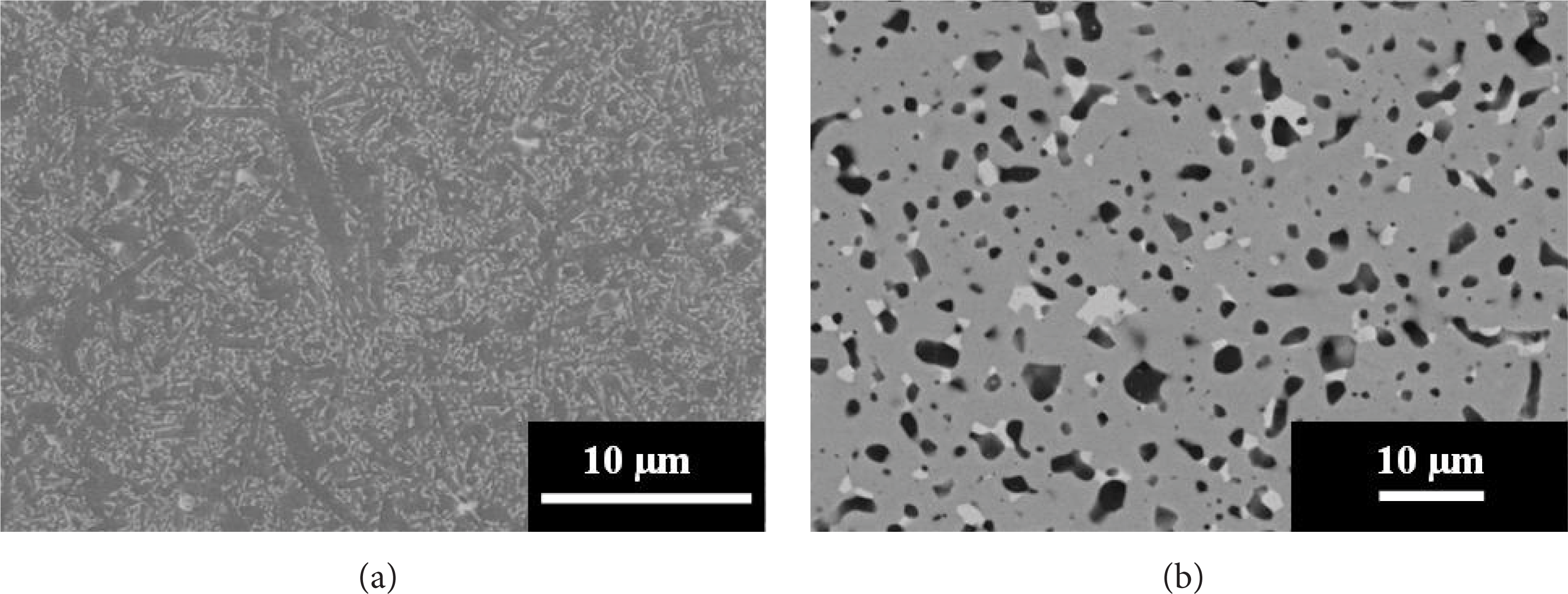
SEM micrograph of plasma etched Si3N4 microstructure (a). SEM micrograph of polished MoSi2 microstructure (b).
The characteristic strength which could be obtained was 643.8 MPa for Si3N4 and 677.6 MPa for MoSi2, with a Weibull modulus of 1.8 and 3.3, respectively. The low Weibull modulus of both series is a result of a wide range of critical flaws, which may be attributed to blocked or malfunctioning nozzles of the printheads. High characteristic strength on the one hand and low Weibull moduli on the other hand indicate that the reliability of the DIP process for the build-up of nonoxide ceramic parts has to be further enhanced. Hardness and fracture toughness of Si3N4 were determined as 15.1 GPa and 8.7 MPam0.5, respectively, while in the case of MoSi2 values of 10.8 GPa and 4.7 MPam0.5 were achieved.
Si3N4 is used as material for structural ceramic parts with severe mechanical load. Prototype miniature gear wheels have been realized by successively printing 10 layers with a thickness of 8 μm, respectively (Figure 7(a)). While the surface of the sintered parts is flaw-free, the contours seem imperfectly rounded (Figure 7(b)). This, however, is not caused by errors during the DIP process but was induced by the transformation of the 3D model file to cross-sectional slices, which are necessary for the printing system [37].

Printed Si3N4 gearwheels (green) (a). SEM picture of sintered Si3N4 gearwheels (b) [37].
Besides the field of structural ceramics, potential applications for Si3N4 are in the field of mechanical sensors (e.g., cantilevers), which is why pillar arrays, as demonstrated in Figure 8(a), were printed. By use of the DIP technology it is possible to place single droplets exactly on top of each other, to realize pillars or similar structures with heights up to 500 μm. The homogeneity of distance between single pillars as well as their uniformity is clearly noticeable [38]. Other functional parts which are interesting concerning the application of nonoxide ceramics are heating elements, for instance. Figure 8(b) shows a printed MoSi2 heating element, consisting of 50 single layers, with good shape accuracy, although single misplaced drops were occasionally identified [38].

3.2. 2D–3D Patterns
As shown in Figure 9, micropillar arrays were printed with alumina ink.
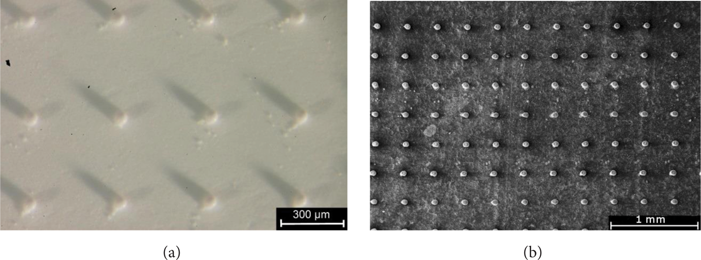
Printed Al2O3 pillar arrays on a disc shaped Al2O3 substrate (a); SEM micrograph of a printed Al2O3 pillar array on a carbon substrate (b).
To observe cell growth, primary structure elements (pillar/pillar or hollow/hollow) were printed with distances from 100 μm to 300 μm. These distances were chosen based on the fact that the cell size is of about 100 μm. To guarantee that cells on these substrates had the same microstructured environment all over the surface, it was crucial to ensure accuracy in distance between those microstructures. In Figure 10 it is evident that DIP is capable of producing such accurate structures.
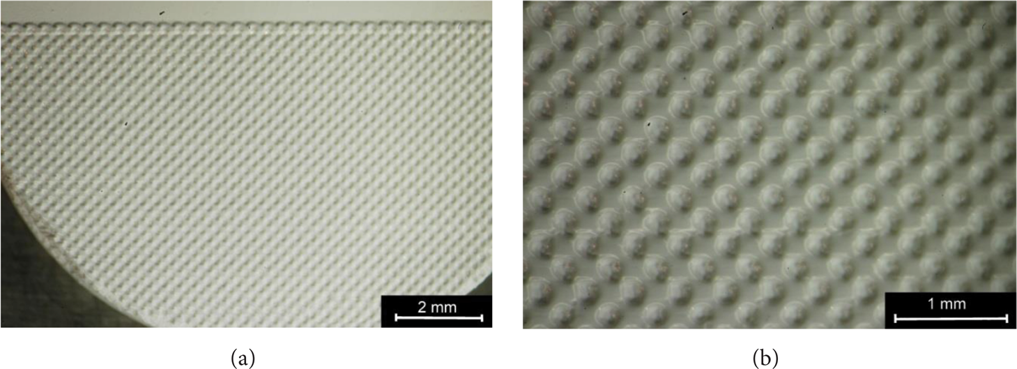
Printed hollows with an Al2O3 suspension on a disc shaped Al2O3 substrate (a); magnification of the same printed structure (b).
3.3. Laminates of ZrO2 and ZTA
Figure 11 shows a SEM micrograph of the cross-section of a printed multimaterial layered specimen perpendicular to the printing direction. The sample consists of successively printed layers of ZTA and 3Y-TZP (each consisting of 10 layers). While a clear distinction between 3Y-TZP (lighter) and ZTA (darker) is shown, the micrograph also clearly features the areas where clogged nozzles for ZTA caused grooves which were subsequently filled with 3Y-TZP. Further magnification shows good bonding between layers of the same material as well as at the interface between different materials (ZTA/3Y-TZP) (Figure 12). No cracks along the interface or delamination were detected.

SEM micrograph of the cross-section of a printed multimaterial layered specimen.

SEM micrograph of the cross-section at the interface of ZTA and 3Y-TZP.
3.4. Functionally Graded Materials
Both ceramic inks were reliably jettable and long term stable. Problems like nozzle clogging or kogation on heating elements were not observed, which is a prerequisite for flawless part production by DIP [48]. Exemplary rectangular FGM parts were produced by printing graded colour models of cyan (=ZrO2) and yellow (=Al2O3) colours. Figure 13 shows the predefined colour gradient (a) and a central section of the surface of the resulting material gradient (b). The presented structure consists of 5 layers, which were printed on top of each other. The process was realized by the modified 3D printing system placing droplets of Al2O3 and ZrO2 ink in direct juxtaposition. After deposition on the substrate the ink was immediately dried, which is why only a marginal mixing of droplets occurred. Nevertheless, it was possible to create smooth material transitions by using this colour printing mode, as shown in the corresponding SEM micrograph (Figure 13(c)).

Colour gradient from yellow (=Al2O3) to cyan (=ZrO2) (a), surface of resulting printed green layers of Al2O3 and ZrO2 (b), and corresponding SEM micrograph (c).
The colour gradation was transformed into an almost stepless material transition. The lower limitation of step size is defined by the diameter of single droplets, as long as they are placed next to each other. By overlapping the droplets, even smoother transitions may be achievable. Compared to previous studies, where solids content was adjusted to values considerably above 25 vol%, the amount of solids of the inks was reduced to 21 vol% in the present study [41]. Contrary to descriptions in literature and to our own experience, this did not cause any drying problems like cracks or bulged layers [21]. The reason for this finding may be found in the printing system, which has been used in the actual study. The amount of ink, which is ejected by the printheads of this adapted powder bed printer, is reduced as compared to other printing systems, which have been used previously. This corresponds to reduced drying periods, which compensates the higher amount of volatile ink components, which evaporate during the drying process.
4. Conclusions
Small zirconia specimens of different shapes (“box with two movable matches”) (Figure 4(a)), channel structure (Figure 4(b)), bridge framework (Figure 5), and rectangular test specimen (Figure 3) were successfully produced by DIP using a thermal inkjet printer. The prepared aqueous zirconia suspension was characterized in terms of particle size distribution, viscosity, density, and surface tension, satisfying all physical requirements for the process. The suspension yielded solids content of 27 vol% and mechanical tests displayed a high B3B flexural strength (1393 MPa; 3 × 4 × 0.3 mm³) and a fracture toughness of up to 8.9 MPam0.5 without any optimization of the microstructure. Additionally, DIP allowed theoretical densities of about 97% to be achieved. It is apparent that the technology is suitable for the production of defect-free, high-strength ceramic components [34].
Furthermore, it has been shown that DIP is a promising technique to establish complex and accurate shaped structures with wall thicknesses of about 200 μm, as well as undercuts and enclosures. Additionally, it was possible to produce accurate structures as needed for in vitro cell tests with the aim of bioactivation of surfaces. Further steps, based on the subsequent observed cell reaction, should include the optimization of the chosen microstructure or even combinations of pillar arrays and printed hollows. Additional interest should be focused on the implementation of an additional y-axis, more parallel working printheads, and a specific printing software to satisfy the nozzle cleaning and deposit drying requirements [36].
Printed laminates of ZrO2 and ZTA showed good bonding between layers of the same material as well as at the interface between different materials (ZTA/3Y-TZP). Further research should look into the mechanical properties of these layered samples as well as the use of different layer thicknesses or even interlocking structures to further enhance the mechanical properties.
Aqueous inks of Si3N4 and MoSi2 with high solids content were developed and used to produce structural and functional parts by layerwise build-up via DIP. High green and sintered densities of printed components resulted in excellent mechanical characteristics. Low Weibull moduli for both materials, however, imply that further optimization of the process technology and material parameters is required. Enhanced reliability would unlock the enormous potential of DIP for the fast and flexible production of complex-shaped nonoxide ceramic parts [37, 38].
FGM structures were realized via DIP by specifically combining highly concentrated aqueous alumina and zirconia inks. The inks were ejected from different printheads on a modified powder bed printer, which allows the combination of single drops on a substrate. Graded structures starting from 100% alumina and 0% zirconia were built up to 0% alumina and 100% zirconia with a smooth material transition. The smoothness of transition is only limited by the droplet size, where a specific overlapping of single droplets could even increase this smoothness. The enormous potential of DIP for the production of FGM was confirmed in our study. The direct deposition of single, picolitre sized droplets, offers possibilities concerning spatially precise material composition, which are not attainable in this way by other shaping techniques at present. Limitations are not process but software related. A file format which includes compositional information inside the volume of a model is necessary to realize three-dimensional parts with material variations in each of the three spatial dimensions simultaneously. This is of utmost interest for many applications, such as bioceramics, where mechanical stress may differ significantly at different positions of one part. The possibility to locally adapt the material composition to this stress, using DIP, may result in substantially increased efficacy and efficiency.
Conflict of Interests
The authors declare that there is no conflict of interests regarding the publication of this paper.
Footnotes
Acknowledgments
The research was kindly supported by the Deutsche Forschungsgemeinschaft (DFG, TE 146/25-1) and in terms of an AiF sponsorship Program of the industriellen Gemeinschaftsforschung (IGF) by the Bundesministerium für Wirtschaft und Technologie (IGF-no. 493 ZN of the Forschungsgemeinschaft der Deutschen Keramischen Gesellschaft e.V.), which is gratefully acknowledged. The authors acknowledge Heraeus Kulzer (Hanau, Germany) for their kind support as well. Raul Bermejo, Marco Deluca, and Robert Danzer (ISFK, Montanuniversität Leoben, and Materials Center Leoben Forschung GmbH, Austria) are gratefully acknowledged for the ball-on-three-balls tests of zirconia specimens.