
Abstract
For firefighters and rescuers, the disaster relief works are difficulty performed in the tunnels because of their constricted space. To reduce the losses of accident, the safety of tunnels and factories should be ordinarily kept under surveillance. Hence, a multisensor based smart tracked vehicle is designed for the application of autonomous detection and surveillance in this paper. Besides, multisensors, communication modules, wireless cameras, an electronic compass, and a GPS module are installed in the vehicle. The key feature is the integration of disaster detection and warning systems so that the vehicle can move autonomously. Furthermore, a LabVIEW graphical programming software is applied to design a human machine interface (HMI) and integrate all systems such that the vehicle can be guided by High Speed Downlink Packet Access (HSHPA) based remote control. Moreover, basic stamp microcontrollers are utilized as its control kernel such that the remote monitoring and control system (RMCS) can be constructed successfully.
1. Introduction
Since 1970, the applications of robots are increasingly diversified. The applications contain the industrial, military, aerospace, and medical and other purposes. In particular, robots not only save human resources, but also replace humans to perform dangerous tasks. In recent years, autonomous mobile robots are developed rapidly [1–6]. In 2004, Yang et al. proposed a combined navigation strategy by two interfaces [1]. The novices can operate rescue robots via the proposed strategy efficiently. Moreover, in order to achieve the intelligent robot positioning function, some scholars [3, 4] proposed different control laws to deal with the path planning and the autonomous navigation. Besides, many researchers presented the integration of multisensors to reduce uncertainty in autonomous mobile robots [5–7]. However, multismart vehicles, which integrated disaster detection, warning system, and autonomous cruise, are rarely explored.
In this paper, a multisensor based smart tracked vehicle is designed for the application of autonomous detection and surveillance. The key feature is the integration of disaster detection and warning systems such that the vehicle can move autonomously. Furthermore, in order to guide the vehicle by HSHPA based remote control, the authors design an HMI and integrate all systems using a LabVIEW graphical programming software. Moreover, basic stamp microcontrollers are utilized as its control kernel such that the RMCS can be constructed successfully.
2. System Architecture
The system architecture, shown in Figure 1, contains a vehicle, a monitoring client, and a communication. The LabVIEW based monitoring client is developed for a human machine interface. Besides, the wireless networks communication between the vehicle and the monitoring client is based on the IEEE 802.11 standards or HSDPA (High Speed Downlink Packet Access). Moreover, the vehicle system consists of a sensor system, a power system, and a control computer.
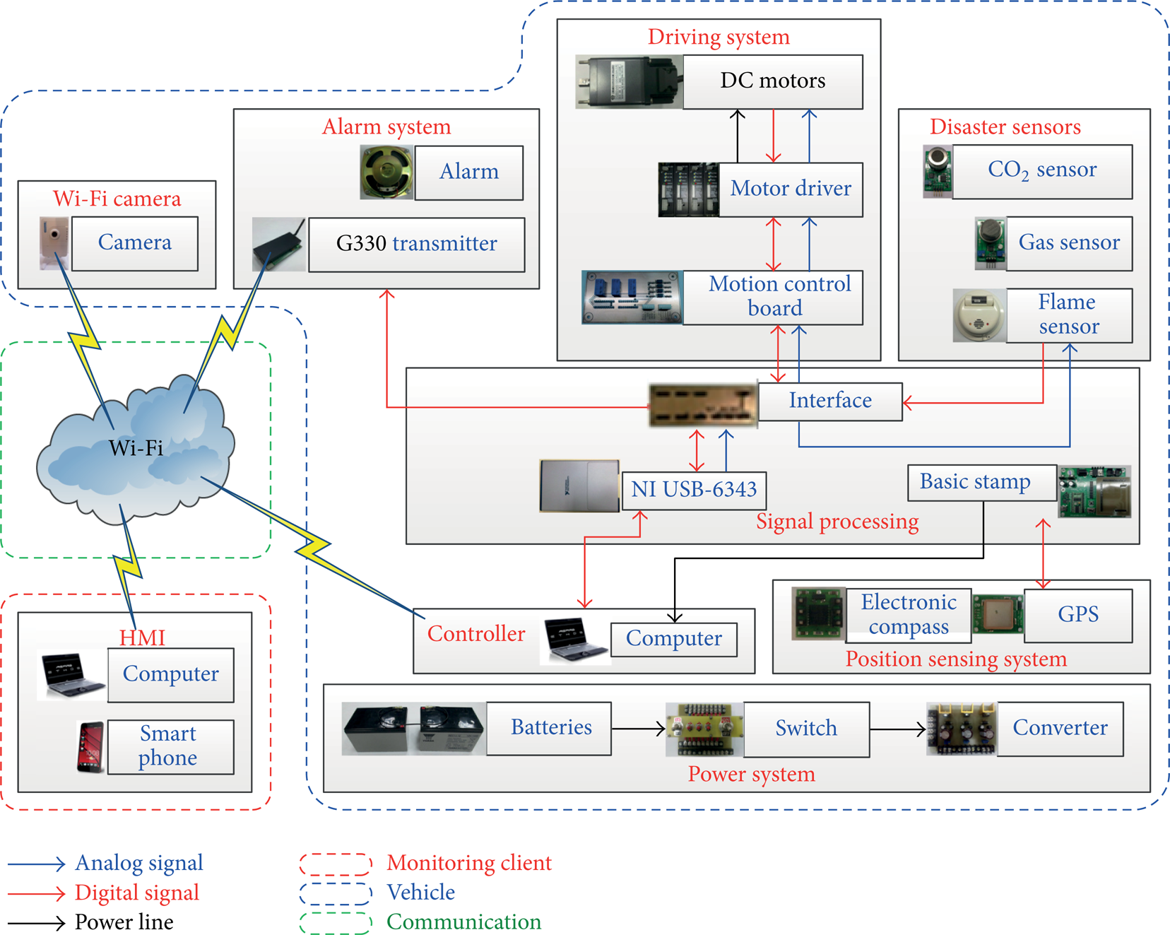
System architecture.
Sensor System. The system includes disaster sensors and a position sensing system. Disaster sensors consist of a CO2 sensor, a nature gas sensor, and a flame sensor. By the aforementioned disaster sensors, this sensor system can not only detect whether there is fire sources and gas leaking in the environment, but also assist firefighters in predetection to minimize the risk of injury. Besides, the position sensing system consists of an electronic compass and GPS. Its main function is to estimate the position and orientation of vehicles.
In addition, we utilize basic stamp microcontrollers (BSM) to calculate the signal values returned by the GPS, and the electronic compass. The integrated module, shown in Figure 2, contains a BSM, a GPS and an electronic compass. In order to transmit signals, we designed a suitable layout of I/O interfaces between BSM, GPS, and the electronic compass.
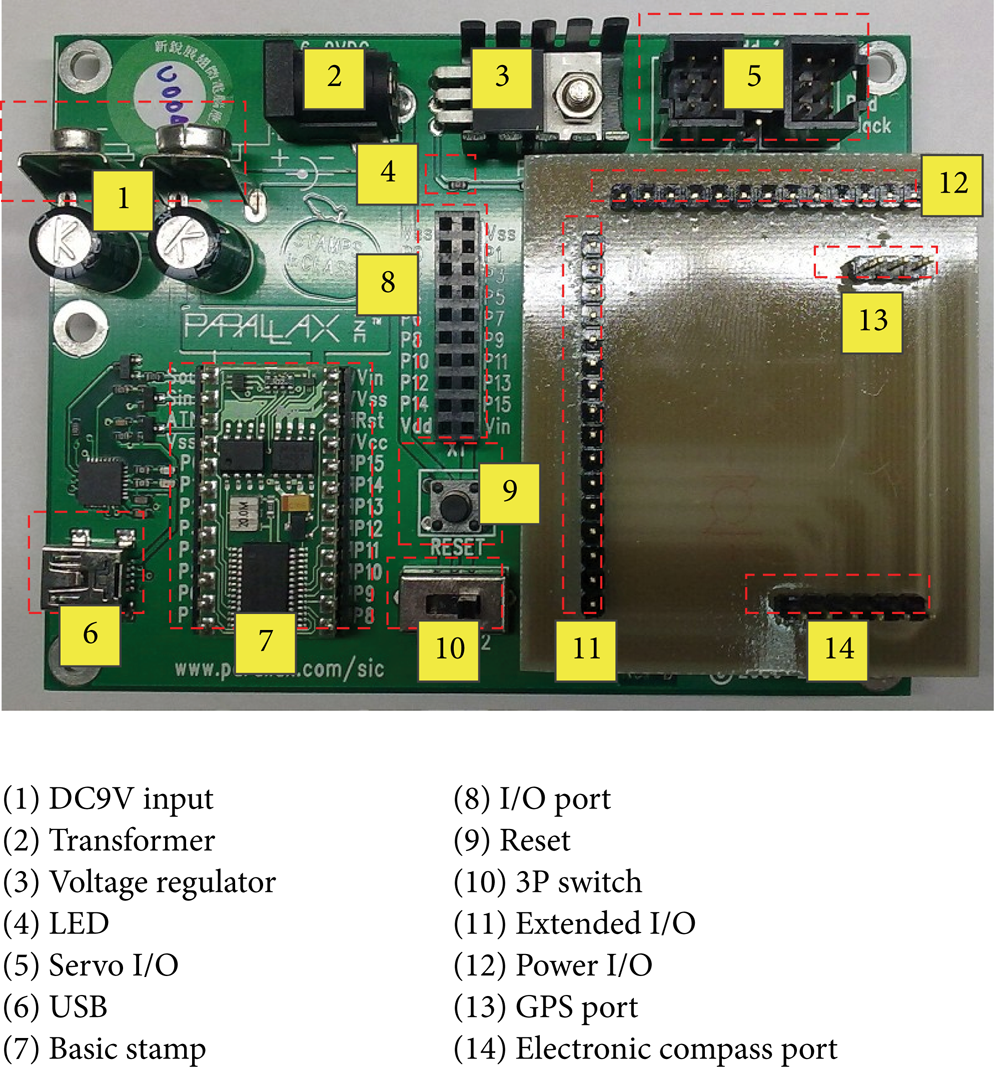
The integrated module.
Power System and Controller. The power system, shown in Figure 3, is composed of two lead-acid batteries as the main source of power supply. Through homemade voltage conversion modules, the system can provide 5 V, 12 V, and 24 V voltage, respectively. Because the efficiency of batteries is particularly important, we measured the discharge capacity of lead-acid batteries, as shown in Figure 4. In this paper, the endurance of the battery is 600 minutes.

The power system.

The discharge capacity of lead-acid batteries (at 25°C).
In order to achieve autonomous navigation capabilities, all signals are transmitted by signal conversion interfaces to PC/controller for processing and path planning. Furthermore, all signals of the alarm and the real-time video are transmitted by a wireless network to the remote monitoring client so that the supervisors can monitor the present condition via PC or handheld communication devices.
Mechanism of the Homemade Vehicle. Recently, many different structures of the rescue vehicles are proposed. In 2006, Ye et al. presented a novel shape-shifting mobile robot system for the urban search and rescue application [8]. Moosavian et al. [9] proposed manufacturing procedures of a teleoperative rescue robot. The following year, Weidong et al. [10] designed a tracked robot for destroyed mine search and rescue. In this paper, we proposed an improved caterpillar mechanism for stair climbing. The proposed vehicle contains an improved caterpillar mechanism, 4 high power DC motors. Moreover, it is assembled by aluminum frameworks. Refer to Figure 5; the homemade intelligent vehicle consists of aluminum extrusion frame. Because the structural strength is sufficient, the vehicle can meet the needs of outdoor mobile carrier. Figure 6 shows the finished vehicle. The sizes of vehicle are illustrated in Figure 7.
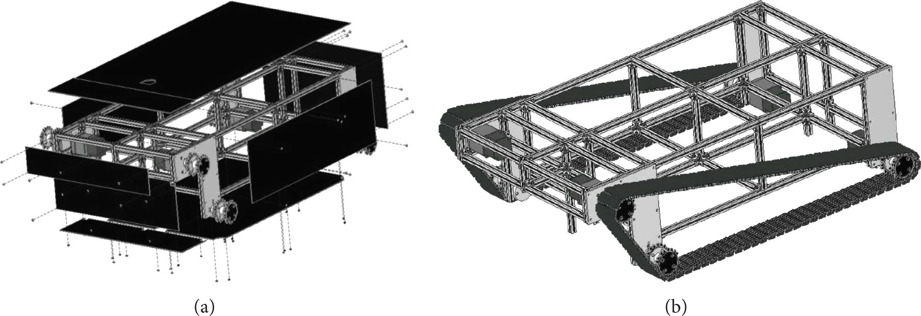
Exploded view of the homemade vehicle.
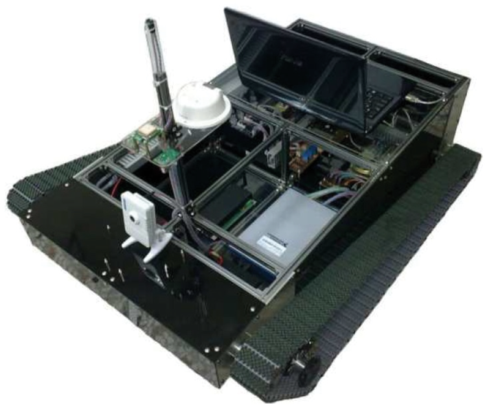
The finished vehicle.

The sizes of vehicle.
3. GPS/DR Navigation
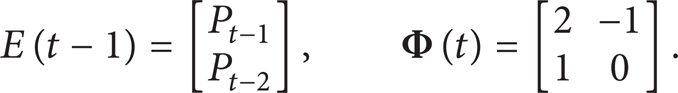
Dead Reckoning (DR). In [11] DR is commonly used in the path planning for autonomous vehicle navigation. In general, when vehicles navigate in the 2D plane, the sailing direction and the moving distance are very important information. Refer to Figure 8; the vehicle location at k-time can be estimated by the following equation:
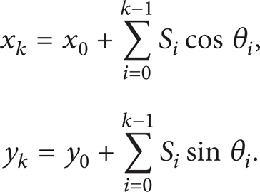
2D dead reckoning.
The most important step of DR is the angle computation between the present vehicle position and next path point. In our system, because the update rate of the electronic compass is larger than that of GPS, the data of electronic compass is used to compute the steering angles. Figure 9 illustrates the steering adjustment values of the vehicle. The forward and back angles of the vehicle are 0°and 180°, respectively. For the calculation of the acceleration, 7 sector boundaries are defined as 0°∼180°, 180°∼360°, 0°∼105°, 225°∼360°, 0°∼45°, 315°∼360°, and 345°∼15°. If the vehicle vector is at 345°∼15°, the orientation is correct. Otherwise, the orientation will be made as an adjustment.

Vehicle steering adjustment.
Kalman Filter. Generally, smart vehicles can autonomously move on two-dimensional plane via electronic compass and GPS. Unfortunately, to enhance the positioning accuracy, the GPS is usually expensive. In this paper, the main purpose is based on low-cost GPS sensors to achieve autonomous navigation function. Besides, the update rate of GPS is 1 Hz. Therefore, in the case of continuous movement of vehicles, we need to use state estimated algorithms to enhance positioning accuracy.
The Kalman filter [12, 13] is a very powerful algorithm. It can effectively estimate the state of dynamic systems. Assume that Newton's system with measurement is described as
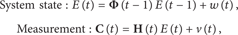
where
The two major steps of Kalman filter are “Prediction” and “Correction,” shown as Figure 10. The goal is to find an equation that computes a posteriori state estimate

The operation of the Kalman filter.
The two-dimensional vehicle motion model can be created via the vehicle location information. Consider the following:
Therefore, the velocity and acceleration could be obtained by every capturing interval. By using the algorithm in Figure 10, the state space of the Kalman filter is

where
Moreover, the parameters of the measurement in (2) are defined as

By this way, the Kalman filter can estimate the continuously moving object. Figure 11 shows the results of the navigation simulation via the Kalman filter and GPS. Blue trace is the actual location of the vehicle. Green and red traces are the GPS measurement result and the Kalman filter estimation result, respectively. From the simulation results, the Kalman filter estimation can not only correct the GPS position offset, but also make the vehicle of a smoother movement.

Navigation simulation results.
4. Experimental Results
Figure 12 indicates the flow chart of the path planning strategy. We can take advantage of the signals of the electronic compass to detect whether the vehicle has deviated from the path.
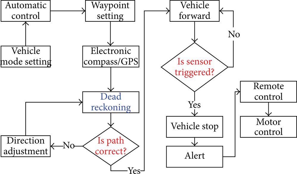
The flow chart of the path planning strategy.
If the actual path is correct, the vehicle will remain cruise. On the contrary, if the sensors are triggered, the vehicle immediately stops and sends a warning message. Meanwhile, to prevent damage of the vehicle, the automatic mode will be switched to the remote mode. Moreover, the HMI, shown as Figure 13, contains a Google map, an electronic compass interface, the vehicle velocity, and the triggered state of the sensors. In addition, the real automatic cruise is shown as Figure 14. By using GPS and the electronic compass, the vehicle can navigate autonomously in outdoor and transmit the real-time images to supervisor client. The video of the vehicle automatic cruise is shown as the hyperlink: http://www.youtube.com/watch?v=PcpE5EeIGCY&feature=youtube. The average maximum path error is 23 cm. In Figure 15, the gas and fire sensors are triggered and the vehicle stops immediately. If the alert is lifted, vehicle the automatic cruise continually.

Human-machine interface.

The real automatic cruise.
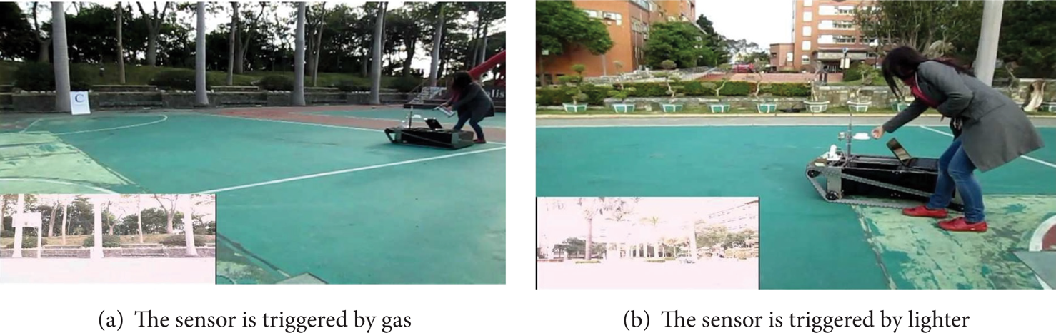
The sensor is triggered by gas and lighter.
5. Summary
In this paper, a multisensor based tracked vehicle is implemented for the autonomous detection and surveillance. The vehicle is equipped with multisensors, communication modules, wireless cameras, an electronic compass, and a GPS module. The main goal is the integration of disaster detection and warning systems so that the vehicle can move autonomously. Furthermore, a LabVIEW graphical programming software is applied to design an HMI and integrate all systems such that the vehicle can be guided by HSHPA based remote control. Moreover, basic stamp microcontrollers are utilized as its control kernel so that the RMCS can be constructed successfully.
Conflict of Interests
The authors declare that there is no conflict of interests regarding the publication of this paper.
Footnotes
Acknowledgments
This research was supported by Ministry of Education under Industry-Academy Cooperation Contract 99E-52-067. The authors express their gratitude for this sponsorship here.