
Abstract
Springback in metal forming process often results in undesirable shape changes in formed parts and leads to deterioration in product quality. Even though springback can be predicted and compensated for through the theories or methodologies established thus far, an increase in manufacturing cost accompanied by a change in die shape is inevitable. In the present paper, it is suggested that the cost accompanied with springback compensation can be minimized while allowing the processing of various three-dimensional curved surfaces by using a flexible die composed of multiple punches. With the die being very flexible, the iterative trial-and-error method can be readily applied to compensate for the springback. Thus, repeated designing and redesigning of solid or matched dies can be avoided, effectively saving considerable time. Only some adjustments of punch height are required. Detailed designs of the flexible die as well as two core algorithms to control the respective punch heights are described in this paper. In addition, a closed-loop system for the springback compensation using the flexible die is proposed. The amount of springback was simulated by a finite element analysis and the modified displacement adjustment (DA) method as the springback compensation model was used in the closed-loop system. This system was applied to a two-dimensional quadratic shape problem, and its robustness was verified by an experiment.
1. Introduction
Springback occurring with removal of constraints is a major cause of shape error in metal forming process and many scientific investigations to eliminate or compensate the shape error have been reported. Increasing sheet tension [1, 2], also referred to as stretch forming, which can be finitely applied to sheet metal forming depending on material's formability [3], was investigated as a typical means for eliminating such shape error. Apart from this method, arc bottoming and pinching die technique were also considered [4]. Although studies on optimizing the forming parameters such as die shape, blank holder force [2], friction [5], and the ratio of radius of curvature to sheet thickness (R/t) [6] and utilizing the hardening model [7] and Bauschinger effect [6, 8] have been carried out to eliminate or reduce the springback, their results are largely dependent on forming processes or material conditions.
Several approaches that are more generic than the preceding method were proposed to control the amount of springback and compensate for it. These approaches iteratively adjust the die shape using a closed loop. Webb and Hardt [9] proposed the deformation transfer function (DTF) between the die and part shapes. This method is based on geometrical information obtained from an experiment. The DTF is defined as the ratio of the measured shape change of the part and die in spatial frequency domain. Although it is very effective when the target shape has a simple geometry such as a two-dimensional shape, its use is limited by the linearity in relationship between shape change of part and die [3]. Karafillis and Boyce [10, 11] presented the force descriptor method (FDM) based on so called spring forward concept in which the die shape is compensated by inversed internal force. Gan and Wagoner [12] show that the displacement adjustment (DA) method is more effective to reach a convergence than the FDM for two-dimensional problems. In the DA, the die shape is adjusted depending on the amount of shape error in the Z-direction between the target and formed shapes after springback. However, the shape error defined only as a vector in the Z-direction cannot represent the springback behavior of curved features. The springback behavior in the X-direction has to be considered in the compensation of the die. Furthermore, this method is sensitive to the algorithm of finding the shape error in X- or Z-directions [3].
In general, the amount and behavior of springback are changed according to the target shape, material, and working environment; thus designing and fabricating a number of compensated dies are inevitable. Although advanced models of compensation such as an accelerated springback compensation method [3], the smooth displacement adjustment (SDA) [13], the surface controlled overbending (SCO) [13], and a combined model with an optimization scheme [14] were suggested, it is difficult to reduce cost and work in practice. To solve this problem, in this work, springback compensation model was employed using a flexible die. The use of a flexible die can result in reduced time and cost to design and manufacture the die [15, 16], since it is capable of changing its forming surface freely. In short, this paper proposes a closed-loop system for springback compensation using the flexible die and a slightly modified DA method.
The flexible die is made of three modules: punch, punch motion control, and joint modules. Its detailed design is mentioned in Section 2. In order to make various forming shapes using only one flexible die, two algorithms are required. The relative heights of the punches in the punch module must be determined. The punch height calculation algorithm described in Section 3 is based on the Bezier-curve equation and it helps in arranging the punch module. In addition, as stated in Section 3, the punch motion control algorithm provides a reasonable engineering design to control the height of punches. In Section 4, the springback compensation procedure using the closed-loop system based on the modified DA method was depicted and applied to a two-dimensional quadratic problem.
2. Design and Manufacturing of Flexible Die
The flexible die, which is composed of a number of punches with adjustable heights to form various three-dimensional curved surfaces, is the main part of a flexible forming technology. As shown in Figure 1, the flexible die (Figure 1(a)) has a superior ability to create various forming surfaces when compared to a conventional solid or matched die (Figure 1(b)) [17]. The structure of a flexible die can be divided into three sections: the punch, control, and joint modules according to their functions. The punch module consists of a number of punches and can attain a three-dimensional forming surface when their heights are adjusted by the control module. The control module is composed of a servomotor set and a linear guide that adjusts the punch's height according to the geometrical information of the target surface. The joint module is necessary for sequential movement between the punch and control modules.
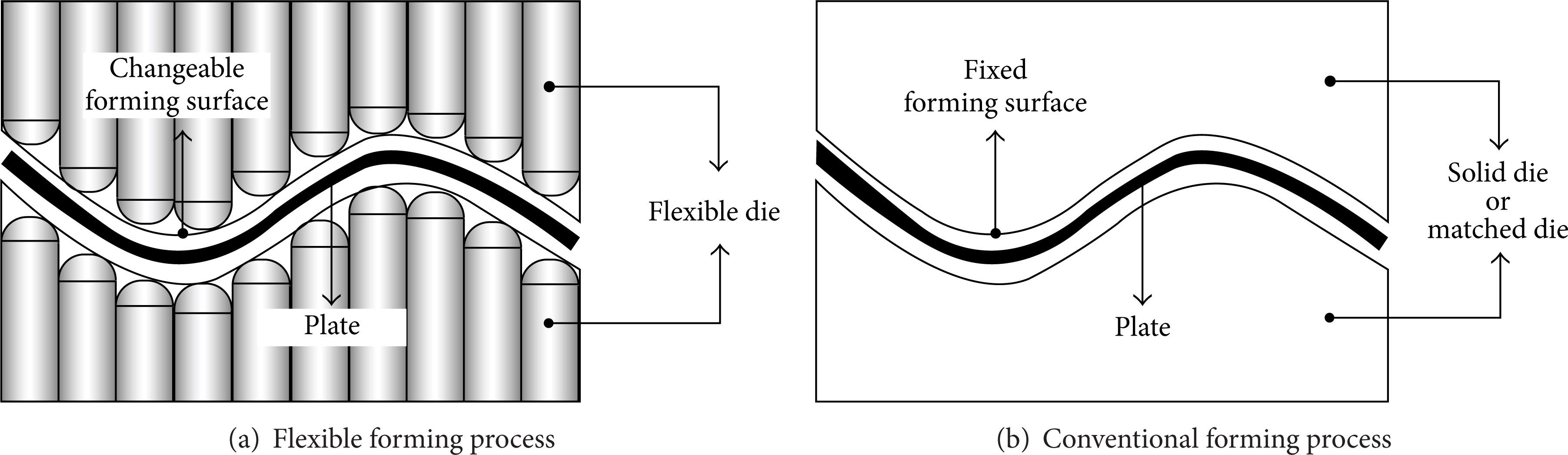
Flexible and conventional forming process.
2.1. Punch Module
Figure 2 illustrates a conceptual design of the punch module. It can be divided into three sections: punch array, side frame, and lower frame, as shown in Figure 2(a). Figure 2(b) shows the top view of the punch module. Punches in the punch array are arranged in a matrix form of M × N and its detailed shape, which is made up of five parts, the head, screw, cap, support, and joint, is described in Figure 3.

Conceptual design of punch module.
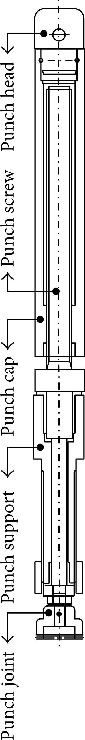
Punch structure.
The punch head is important in the flexible forming process, since this part is in contact with the forming material as described in Figure 4. The contact point, which can be identified from the geometries of the punch head and forming surface, determines the relative height of the punches (a detailed description is given in Section 3.1). Obviously, the form error in punch head translates to a shape error in the final part due to a difference between the target shape and the forming surface. The punch head was processed to a hemisphere having a radius of r p with a high degree of precision as shown in Figure 5.

Contact point between punch head and plate.

Shape of punch head.
Once the relative height of punches was determined, the height was adjusted by a screw motion between the punch screw and cap as illustrated in Figure 6. The outer surface of the punch screw was fabricated as a male screw and the inner surface of the punch cap was processed as a female screw. The heights of the punches were controlled by the number of revolutions of screw. Additionally, the female screw was processed in a limited area, also called an effective region, in order to minimize the friction generated by the combination of the punch screw and cap. The required torque, which increases with friction, was minimized by reducing the length of the effective region. The reduction in friction subsequently reduced manufacturing costs.
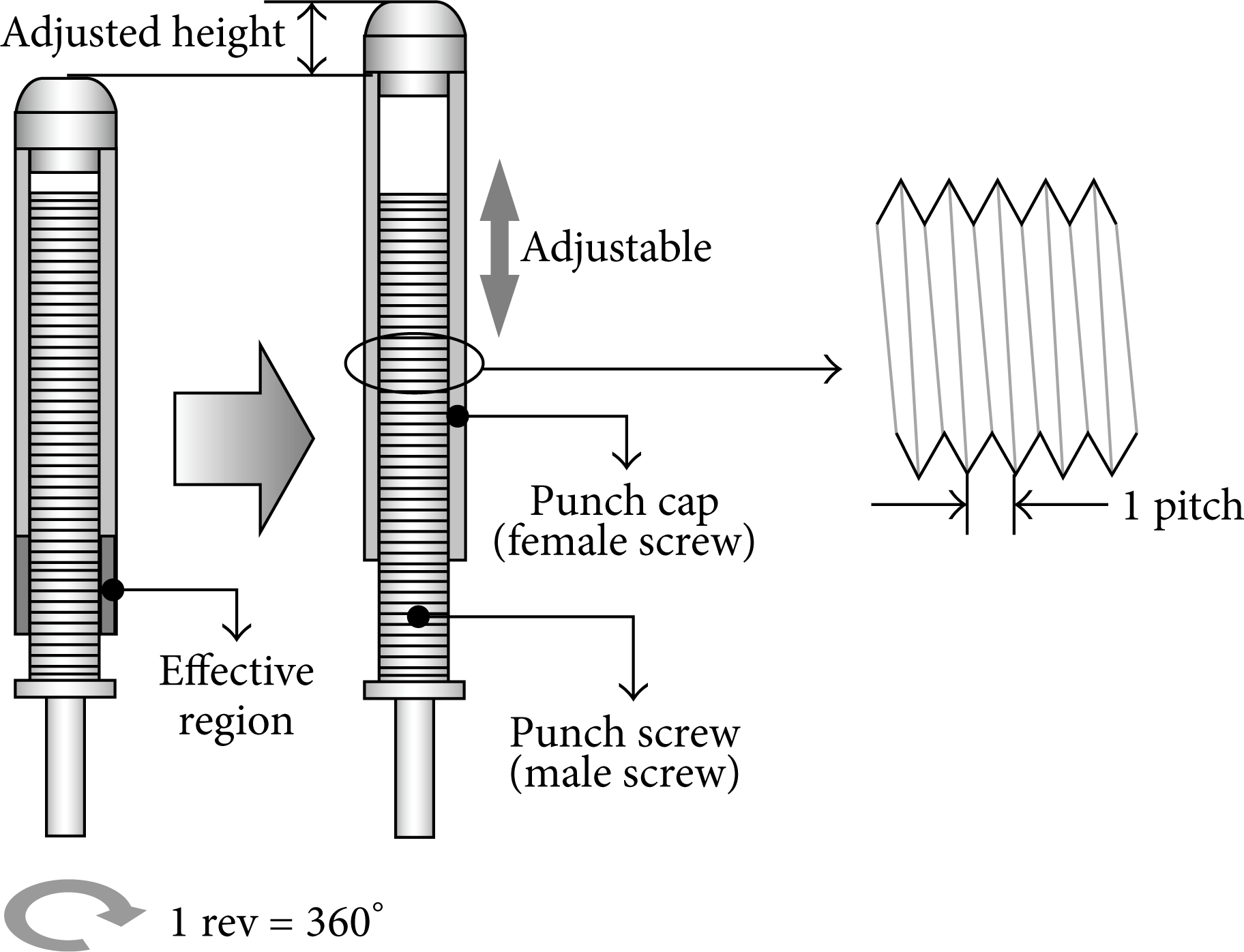
Illustration of punch height adjustment by screw motion.
As described in Figure 2(a), the punch support was connected with the lower frame of the punch module to keep the formation of the punch array. The function of the punch joint is to connect the punch with the joint module. Its role is mentioned along with that of the joint module in Subsection 2.3.
The punches are assembled into a punch array in M × N matrix form and its size is determined by the size of each punch. As shown in Figure 5, the punch size, Pwidth, is twice as much as the punch tip radius, r p , since the punch head has a hemispherical shape. If the size of the flexible die is defined by × W[mm2], M and N are determined by the relationship

We set both L and W to be multiples of 2r p . The punch array used in this work is 15 × 10, since the size of flexible die is 300 × 200 mm2 and the punch tip radius is 10 mm. The lower frame and the side frame support the forming load to maintain the formation of the punch array.
2.2. Punch Motion Control Module
The flexible forming process is significantly different from the conventional forming process using a solid die. Arranging the punch array is necessary to form a sheet metal. To construct the forming surface corresponding to a target surface, the respective punch's height has to be adjusted using the punch motion control module. As mentioned briefly in Subsection 2.1, the relative height of punches can be adjusted by a rotary motion transferred from the servomotor in the control module to the punch and its change in height, Δh, is defined by the pitch and revolution angle, rev, as shown in Figure 6.
In flexible forming, time is required to arrange the punch array prior to a forming. The best solution to minimize the arranging time of all punches is to have a one to one match between punches and servomotors as presented in Figure 7. The heights of all punches inside the punch array of M × N can be adjusted by servomotors of M × N at a time. However, the manufacturing cost greatly increases when a larger forming area or a smaller punch size is required. Additionally, larger power consumption is required and the design of the motion controller will be complicated. If the punch size is smaller than that of the servomotor, it is complex to install the servomotor in the control module. Consequently, the one to one control system may not be optimum due to the increase in manufacturing cost. In this study, the control module was designed as a compromise using a servomotor set composed of a limited number of servomotors and linear guides.

Control system with a one to one match between punches and servomotors.
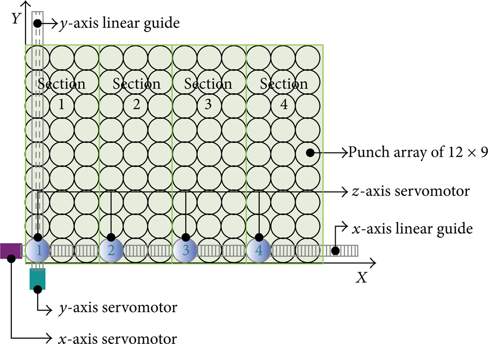
Figure 8 illustrates the conceptual design of the servomotor set. The z-axis and x-axis servomotors were transferred along the Y-direction using the y-axis servomotor connected to another linear guide. In this way, the height of all punches was adjusted. Figure 9 describes an example of a servomotor set, which is composed of six servomotors and two linear guides to control the 12 × 9 punch array. The composition of the servomotor set differs according to the size of the punch and the punch array. In this research, four servomotors including two Z-axis servomotors were used in one flexible die.

Conceptual design of a servomotor set.
Example for servomotor set arrangement.
Another point to consider in designing the control module is the torque required in transferring the rotary motion. In order to reduce the power consumption of servomotors associated with large torques and to reduce manufacturing costs, the torque required for motion control was calculated using a geometric coefficient of friction as represented in Figure 10. The torque required to move up and down (T u and T d , resp.) was calculated as follows [18]:

Using this estimated torque, the Panasonic A4 series with output of 100 W (MSMD012P1S) was selected and their permitted torque is 0.5 Nm in a continuous running range. A capability margin was also considered.

Geometrical coefficient of square thread.
2.3. Joint Module
The punch height is controlled by the servomotor in the control module. This was achieved by utilizing the servomotor set to control the punch heights sequentially since it is impossible to install the servomotor on all punches due to limitations of cost and space. There are two functions performed by the joint module. Firstly, as shown in Figure 11, joint and disjoint motions were included into the sequential movement of servomotors. The joint module was designed to be connected with the punch joint. Figure 12(a) shows a conceptual diagram of the joint module in combination with the punch joint. Secondly, it transfers the rotary motion to the punch by a combination of the punch joint and furrow of joint module. Figure 12(b) describes a detailed design of the joint module.
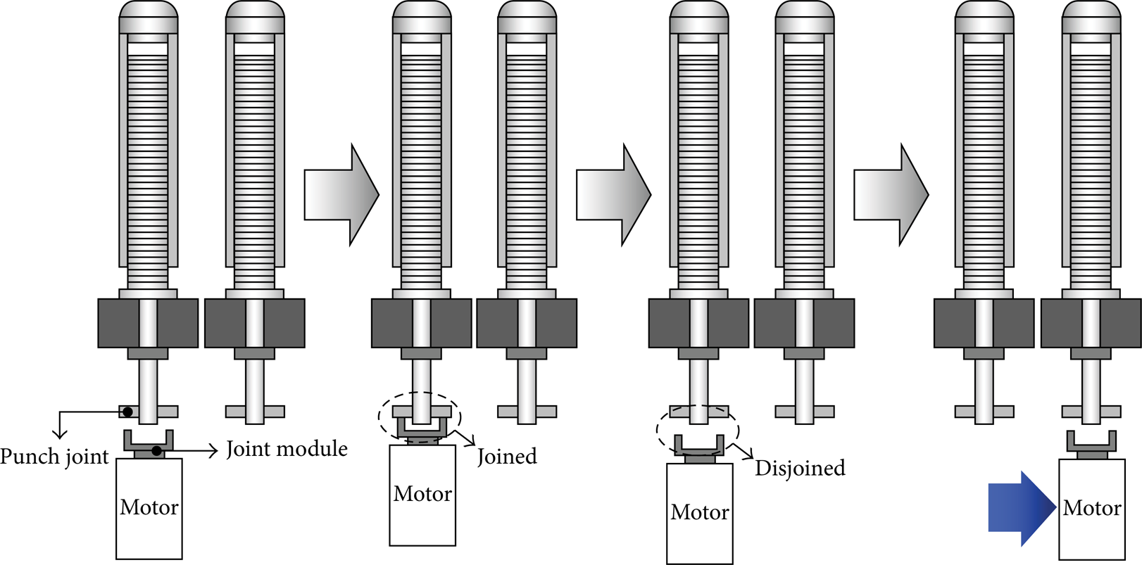
Joint and disjoint motion between punch and servomotor.

Joint module design.
2.4. Flexible Forming Apparatus
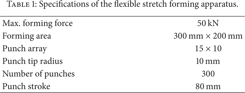
Based on the detailed design of the respective modules, the flexible die was fabricated. The punch size, punch head radius, and forming area were 20 mm, 10 mm, and 300 mm × 200 mm, respectively. Accordingly, the punch array was determined by a 15 by 10 matrix. The upper and lower punch modules were manufactured as described in Figure 13 and their specifications are summarized in Table 1. Two control modules are located in the upper and lower parts of the punch module. The servomotor set described in Figure 14(a) was composed of two Z-axis servomotors and X- and Y-axis servomotors, which determined the position of the Z-axis servomotors in the X-Y plane. The joint module and punch joint are shown in Figure 14(b). The joint module enables the servomotor to connect and disconnect from the punches and facilitates the sequential control of the punches. The joint and disjoint operation of joint module is controlled hydraulically.
Specifications of the flexible stretch forming apparatus.

Flexible forming apparatus.

The device for sequential movement of servomotor.
3. Development of Algorithms for Punch Motion Control
3.1. Punch Height Calculation Algorithm
In the forming process adapting a flexible die, the relative height of punches has to be determined to construct the forming surface for the required target surface. Accurate calculation of relative height is required for the minimization of forming error induced by the difference between the forming and target surfaces. The relative height, at first, was calculated by paying attention to the two-dimensional quadratic shape having a constant radius of curvature, and then, this scheme was expanded to an arbitrary two-dimensional quadratic shape. Further, the punch height calculation algorithm is based on the Bezier-curve equation.
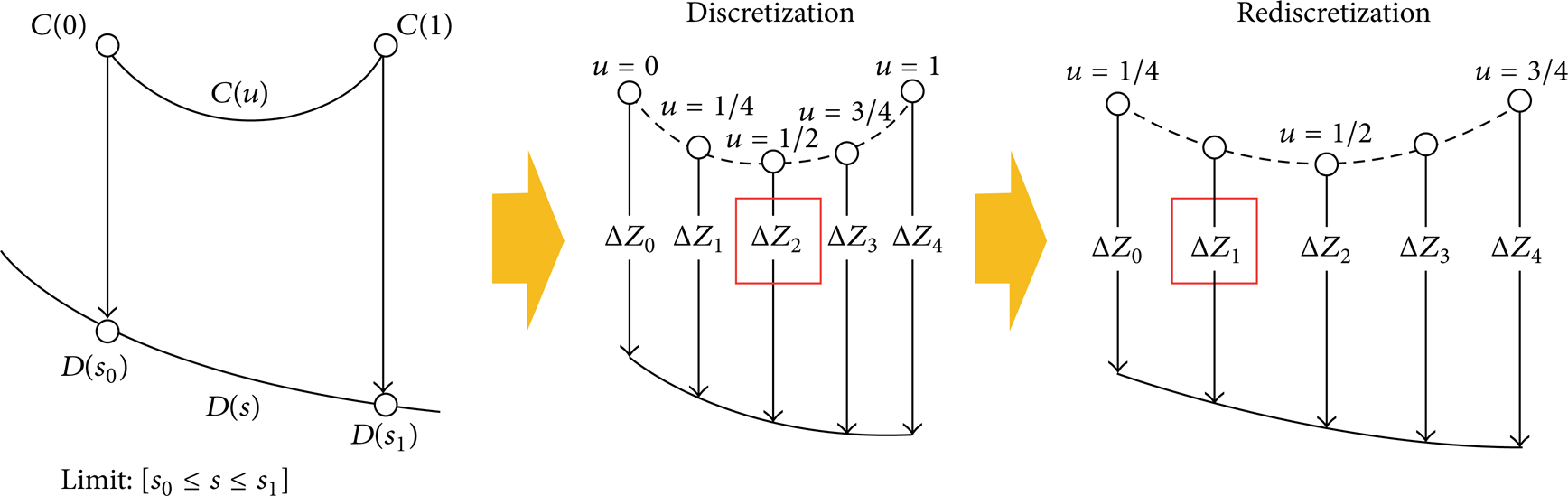
Since the punch is fixed to the lower frame, all of the punches are constrained in the X- and Y-directions and can be only adjusted along the Z-direction. As shown in Figure 15, each punch is moved from its initial position along the Z-direction to the target surface. The relative height of the ith punch, ΔZ i , can be defined as the distance from the initial point to the final point in the Z-direction. The final position of the punch is determined by the contact point between the punch and the target surface. It is possible to calculate the punch height by measuring the moving distance of the contact point. In effect the calculated punch height is the minimum distance between the punch and target surface in the Z-direction. Regardless of the shape of the punch head and target surface, this scheme, also called the minimum distance method, is used to calculate the relative height of punches.
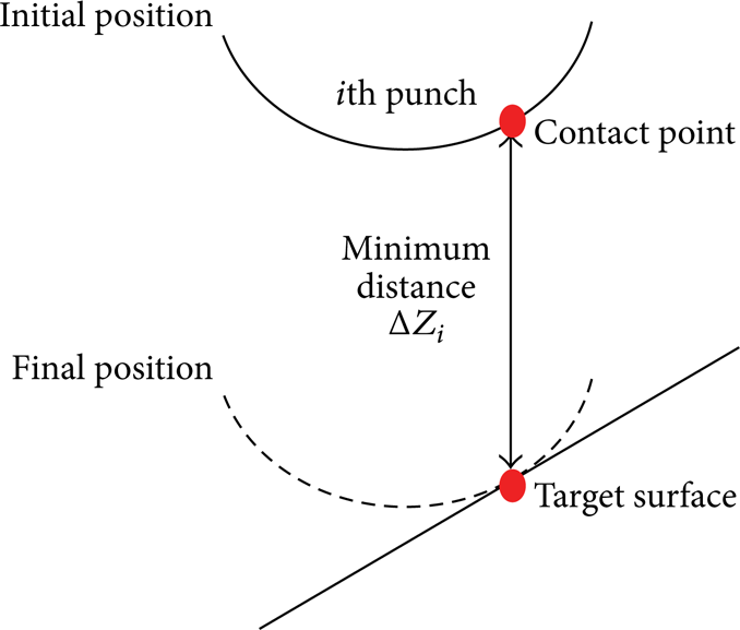
Minimum distance method.
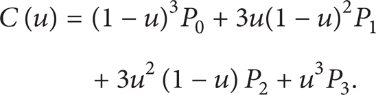
To calculate the minimum distance between the punch and target surface, a curved surface has to be expressed mathematically. Among the various mathematical equations for curved surfaces, a parametric equation was selected considering the convenience of using it in a computer program. Of particular importance is the third-order Bezier-curve equation, which determines a curve using four control points as shown in Figure 16, which was used in this study. It is expressed as

where u is a parameter and P i indicates the control points. B i,n is a basis function expressed by the Bernstein polynomial:

Rewrite the third-order Bezier-curve equation
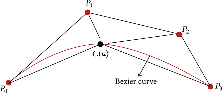
Third-order Bezier curve and its control point.
Using (4), the shape of each punch head and that of the target surface can be expressed mathematically. To obtain the Bezier-curve equation with respect to a given shape defined by the radius of curvature, R, four control points need to be defined. Fortunately, P0 and P3 are determined by both end points of a given curve and we know that the P1 and P2 are on a tangent line at both end points. As a result, in the case of the quadratic shape of punch head or target surface having a constant radius of curvature r p or R, P1 or P2 will remain as an unknown variable by the symmetry condition. Also, assuming that there is no error at the center point, P1 or P2 can be determined. Eventually, all of the control points can be expressed as a function of the radius of curvature and the end points. In arbitrary quadratic shape defined by only the end points, unlike the previous case, P1 and P2 cannot be calculated explicitly. In this case, they must be estimated by trial and error.
Because the quadratic surface can be expressed by mathematical model, it is possible to calculate the relative height of punches using the minimum distance method. The punch height calculation procedure is illustrated in Figure 17 and can be summarized as follows:
surface modeling using a Bezier-curve equation;
projection of the discretized points onto the target surface and determination of ΔZ i ;
adjustment parameter range of punch according to i;
repeating previous procedure until convergence;
repeating procedures 2 to 4 for all punches.
Punch height calculation procedure.
In the first step, two Bezier-curve equations, C(u) and D(s), are defined with respect to punch head shape and target surface, respectively. In sequence, the distance in the Z-direction is calculated at the discretized points, and then the minimum distance, ΔZ i , is found out by comparison. Since the shape of the punch head is always convex, there is an actual minimum distance around point i. Therefore, in the third step, the second step is repeated after the range of parameter is limited to points adjacent to the ith point. All of these procedures are carried out until a convergence is achieved. All of the relative punch heights can be obtained by repeating the second, third, and fourth steps. A remaining assignment to conduct the flexible forming process is a punch motion control.
3.2. Punch Motion Control Algorithm
There are two types of punch motion control, fixed and positive [19]. The former uses the flexible die arranged to the target surface as shown in Figure 18(a); this method is suitable for forming simple curved surfaces, because the forming procedure is more concise. On the other hand, the positive type illustrated in Figure 18(b) is a real-time control method. In the forming procedure, all the punches always make contact with the forming material and the forming load is transferred from the punch to the material. The formability can be increased by avoiding local deformation. However, it is difficult to control the punch height and the forming load simultaneously and the manufacturing cost becomes high due to a number of control units. In the present work, a fixed control type using a servomotor set was selected.

Punch control type of flexible forming process.
Figure 19 shows the overall data flow in the punch motion control. Firstly, the current state of all of the punches is loaded with the target position calculated by the punch height calculation method. Using this data, a punch motion data, which describes the difference between current and target positions of the respective punches, is generated. If the punch motion data is larger than 0.05 mm, this algorithm returns to 1 as a value of motion factor. On the contrary, 0 is returned to the motion factor matrix. This procedure is to reduce the time used to construct the forming surface. The motion factor was made of 0 or 1 in the M × N matrix form. In the next step, the motion path is determined. As mentioned before the punch array is a number of sections according to k, which is a number of Z-axis servomotors. This means that a number of controlled punches are k in one step. If all of the motion factors of k punches have a value of 0, there is no need to operate the servomotor set. The motion path is defined by the summation of motion factors and its value is evaluated to activate the control or not. The servomotor set is operated when the motion path is larger than 0. All of the punches are controlled according to this algorithm established using LABVIEW 8.6.

Punch control algorithm.
Figure 20 shows the moving pattern of the servomotor set according to the motion path. Figure 20(a) illustrates the initial state of the servomotor set and the motion path. The red color indicates that the value of motion factor is 1. Three sequences are needed to adjust the punch height. Firstly, the Z-axis servomotors are moved by the X-axis servomotor and then 1st and 4th Z-axis servomotors are operating as shown in Figure 20(b). The next sequence is illustrated in Figure 20(c). The X- and Z-axis servomotors are moved to the second target point along the Y-direction and then four-punch height is controlled. A similar sequence is repeated in the third step as shown in Figure 20(d). Finally, the servomotor set is moved to the initial position.

Example for movement of servomotor set by motion path.
3.3. Realization of Forming Surface
Using these algorithms a forming surface of quadratic type was constructed as shown in Figure 21. This configuration having a single radius of curvature of 300 mm was used as the target surface in springback compensation using the DA method.

Quadratic type 3D forming surface.
4. Springback Compensation Based on DA Method
The flexible forming apparatus was developed in this study with the objective to compensate the springback at a minimum cost. The closed-loop system, which is based on a slightly modified DA method, is suggested for springback compensation.
4.1. Closed-Loop System Based on DA Method
The DA method proposed by Gan and Wagoner is summarized as follows (Figure 22) [12].
A trial die shape is defined (for the first iteration, the die shape is the same as the target shape).
A FE simulation was performed.
The formed shape after springback was compared with its target and the shape error is defined as the vector of Z-coordinates.
The shape error is added to the nodal coordinate in the current die.

DA procedure.
Since the target surface is of quadratic shape representing a curved feature, a slight modification was applied to the DA method. In addition, the punch height calculation procedure was incorporated in it. A modified DA procedure is described as follows.
A trial die shape is defined (for the first iteration, the die shape is the same as the target shape).
Calculating the punch height using a Bezier-curve equation and the flexible die is modeled.
Obtain the formed shape by a FE simulation that incorporates springback analysis.
The formed shape is compared to its target and the shape error is defined as the vector of X- and Z- coordinates.
The inversed shape error is added to the nodal coordinates in the current die shape.
Obtain new die shape in the form of a Bezier-curve equation by trial and error.
Repeat steps 2 to 6 until the die shape is optimized.
Figure 23 shows the closed-loop system for springback compensation. Once the target shape is defined, a die shape is determined as the target shape in the first iteration. Then, a final shape after springback can be obtained through an explicit-implicit sequential FE simulation, and the detailed contents of this FE simulation are explained in Section 4.1.1. The number of iterations in the simulations is governed by the shape error, ε s , calculated by the root mean square (RMS) error method. In this equation, Δy2 was defined as follows:

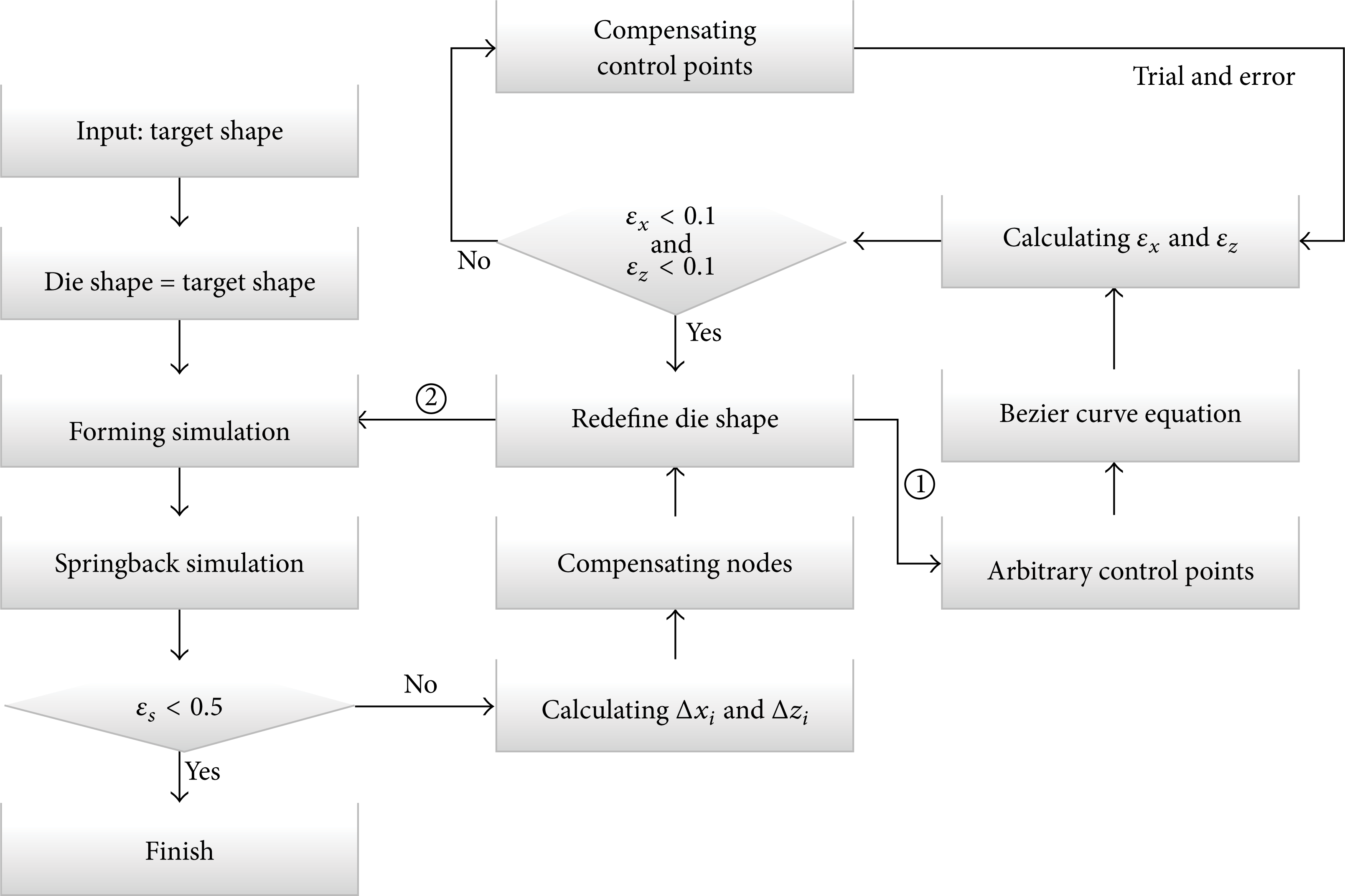
Flow chart for springback compensation.
If the shape error is larger than a critical value, for example, 0.5 mm as in this study, an additional iteration is carried out. In the case of less than 0.5 mm, the amount of elastic recovery is very small. Thus it is regarded as meaningless value, and it is not necessary to do springback compensation. In this step, the surface nodes defining the die surface in the previous step are compensated in the opposite direction to the springback error. Then, the redefined die shape is expressed as the Bezier-curve equation by trial and error, since it is defined by compensated nodal coordinate not curvature radius. As a result the compensated FE model can be obtained and a similar procedure is repeated until the optimized die shape is determined.
The springback compensation model using the flexible die is clearly defined. However, one assumption was overlooked throughout the description of the compensation model. Efforts were made to accurately predict the springback using the FE code [20] and the FE model presented in this work was established in a similar manner. Before the presentation of the results, the FE model used to predict the springback error is reviewed in the following text.
4.1.1. FE Simulation
There is a sequential coupling between the FE simulation and the springback compensation algorithm. Since the DA method is based on the simulation result, its robustness must be guaranteed. The FE model, which is composed of plate, elastic pad, and lower and upper dies, was constructed using ANSYS Parametric Design Language (APDL) supported by ANSYS as shown in Figure 24. The initial size of the plate was 300 mm × 200 mm and its thickness was 4 mm. The material properties of the mild steel plate are summarized in Table 2 and the work-hardening model;

where C10 and C01 are the material properties obtained from a compression test. Figure 25 shows the nominal stress versus nominal strain curve of a urethane pad with a shore A hardness of 90.
Material properties of ASTM A36.


FE simulation model and result.

Nominal stress versus nominal strain curve.
The punch module had an array of 15 × 10 and the punch tip radius was 10 mm. Each punch was arranged and modeled using the relative heights obtained from the punch height calculation algorithm. The upper and lower dies were set to form the target surface to a radius of curvature of 300 mm. The upper die represents a solid die of quadratic shape having a radius of curvature of 295 mm offset from the target surface in a concave direction by as much as the thickness of the elastic pad. On the other hand, the radius of curvature of the lower die is 309 mm offset from target surface in convex direction as much as the sum of thicknesses of the elastic pad and the plate. These dies are assumed to be rigid bodies and the friction coefficient was assumed to be 0.2.
The forming simulation was carried out using the LS-Dyna solver in ANSYS. Since this solver is based on an explicit scheme, the long-term static deformation is not directly obtained [22]. Therefore the explicit-implicit sequential method [23] was used to analyze the springback. This method transfers the results of the explicit forming simulation into an implicit code and carries out a simple residual stress calculation to obtain the long-term static condition. In this study, the springback simulation was performed by ANSYS. The elastic recovery occurred in the plate; only the plate was considered in this step.
To verify the simulation result, an experiment was carried out as shown in Figure 26 and its concave surface was measured using a three-dimensional shape scanner. The plate was made of ASTM A36 steel with a thickness of 4 mm. The result of the experiment was measured by 3D scanner for the comparison of curvature. The simulation and experimental result are plotted with the target surface in Figure 27. The formed surface before springback is almost the same as the target surface. This implies that the conventional solid die could be replaced with a flexible die. Consequently, it can be seen that the formed shape after springback agrees with the experimental result.

Flexible forming experiment and result.

Comparison of results from simulation and experiment.
4.2. Springback Compensation
The target surface in the closed-loop system is the same as the shape used in the FE simulation. The previous result can be applied to the first iteration in the closed-loop system. This shows that the final formed shape, that is, the formed shape after springback, is different than the target shape. The calculated springback error, ε s , was 5.21 mm which is much larger than 0.5. Therefore, a second iteration was used. In the second iteration, the springback errors in the X- and Z-directions were calculated and then the compensated node was determined by the following relationship (Figure 28):


Compensation process using springback error.
In order to calculate the relative height of punches with respect to the compensated die shape, the Bezier-curve equation was defined based on the compensated node. Figure 29 shows the redefined die surfaces by the trial-and-error method. Notably, the Bezier-curve equations represent the compensated nodes well with regard to the upper and lower surfaces. Figure 30 is the final result after the second iteration. The formed shape using the modified DA method agrees well with the target surface because the springback error is lower than 0.5 mm. This is further verified by the experimental curve showing a similar result. The closed-loop system was finished in this step and the final die shape was obtained.

Compensated forming surface after the second iteration.

Final result.
5. Conclusion
This work was performed to obtain the desired metal part shape with a minimum cost. To compensate for springback, a closed-loop system was proposed. The flexible forming technique and a modified DA method based on FE simulations were used. Detailed designs of all the modules of the flexible die such as punch, control, and joint modules were made. Eventually, the flexible forming apparatus was fabricated and used in this study for experiments. In order to operate this apparatus, two algorithms for punch height calculation and punch motion control were developed. The former was to provide the relative height of punches in order for the punch module to represent the target surface. The die surface and the shape of the punch head were expressed by a Bezier-curve equation for the curved surface. Based on these equations, the relative height of the punches was calculated by the minimum distance method. The latter has the common goal with the former. However, its main goal is to control the height of each punch using the servomotor set. The closed-loop system for springback compensation was applied to a simple two-dimensional problem. The springback error converges rapidly and was verified by experiments.
The springback compensation method using the flexible die proposed in this study was developed into a detailed design from a conceptual design. Although a simple two-dimensional problem was considered in this study, more complex three-dimensional problems will be studied in future work. Expanding of the punch height calculation method and the effectiveness of the springback compensation model such as the DA method in complex problems will also be considered in subsequent work.
Conflict of Interests
The authors declare that there is no conflict of interests regarding the publication of this paper.
Footnotes
Acknowledgments
This work was supported by the National Research Foundation of Korea (NRF) Grant funded by the Korea government (MSIP) through the Engineering Research Center (no. 2012R1A5A1048294) and the Human Resource Training Project for Regional Innovation (no. 2012H1B8A2026095).