
Abstract
This study numerically investigated the influence of using the second row of a double-row deswirl vane as the inlet guide vane of the second stage on the performance of the first stage in a two-stage refrigeration centrifugal compressor. The working fluid was R134a, and the turbulence model was the Spalart-Allmaras model. The parameters discussed included the cutting position of the deswirl vane, the staggered angle of two rows of vane, and the rotation angle of the second row. The results showed that the performance of staggered angle 7.5° was better than that of 15° or 22.5°. When the staggered angle was 7.5°, the performance of cutting at 1/3 and 1/2 of the original deswirl vane length was slightly different from that of the original vane but obviously better than that of cutting at 2/3. When the staggered angle was 15°, the cutting position influenced the performance slightly. At a low flow rate prone to surge, when the second row at a staggered angle 7.5° cutting at the half of vane rotated 10°, the efficiency was reduced by only about 0.6%, and 10% of the swirl remained as the preswirl of the second stage, which is generally better than other designs.
1. Introduction
In addition to high full load efficiency, the partial load efficiency of the two-stage centrifugal chiller shall be increased, as the chiller usually operates under partial load. In addition to efficiency, an extensive range of operation or a low surge flow rate is of great importance in chiller operation. Most current two-stage refrigeration centrifugal compressors are the inline type, with a return channel and a deswirl vane, as shown in Figure 1. The deswirl vane of a compressor recovers the diffuser outlet tangential velocity into static pressure, allowing the refrigerant to enter the second stage without pre-swirl, thus, increasing the compression ratio of the second stage.

Schematic diagram of the first stage of a centrifugal compressor.
With the help of intercooler-economizer, the coefficient of performance of a two-stage chiller is mostly (not always) better than a single stage chiller at full load condition. However, partial load performance and the surge flow rate of a two-stage chiller are not necessarily better than those of single stage one. In an inline type two-stage refrigeration centrifugal compressor, under partial load, the first stage uses inlet guide vanes (IGV) to postpone the surge, but there is no IGV for postponing the surge of the second stage. Therefore, several compressor manufacturers have designed all or part of deswirl vanes as rotatable vanes. The deswirl vane rotates a certain angle at low flow rate, partial swirl is reserved as the preswirl of the second stage, and the deswirl vane is regarded as the IGV of the second stage. Thus, there are IGVs at the first stage and second stage under partial load in order to assist the compressor to delay the surge.
In terms of the studies related to deswirl vanes, Lenke and Simon [1] used numerical calculation to discuss the flow field in the deswirl vane. They used two different turbulence models to calculate the flow field under full load and partial load. The result was compared with experiments, while the difference between the two turbulence models in the flow field at the full load was very small; the difference in the flow field under partial load was significant. Motohiko et al. [2] used CFD to calculate the first compression stage with deswirl vane. The detailed flow field showed that the flow separation inside the diffuser extended to the suction surface of the deswirl vane. Veress [3] indicated that the use of a deswirl vane and its blade profile was special; thus, it could not be designed by referring to other blade shapes, and new design methods must be developed. The paper used CBL (constant blade loading) and the inverse design method to build the blade shape. Finally, three-dimensional flow field analysis was conducted for validation. Veress and van den Braembussche [4] designed a three-dimensional deswirl vane, where the leading edge of the vane was at the inlet of the return channel, and analysis results of the three-dimensional Navior-Stokes equation showed that the performance was better than the traditional two-dimensional vane. Wang and Chen [5] used numerical calculation to discuss the influence of flow separation in return channel and deswirl vane on the second stage impeller; if the flow entered the return channel with a very high tangential velocity, the return channel had flow separation. This flow separation entered the deswirl vane to generate secondary flow, which made the flow field very complex. Cambio [6] indicated that mounting an IGV at the inlet of the two stages actually contributed to increasing the efficiency of partial load and reducing the surge flow rate. However, the cost derived from the second stage IGV must be considered. Seki et al. [7] experimentally proved that the energy consumption of a two-row IGV was lower than the traditional design by about 6%. Besides, under partial loads, the pressure loss of rotating part of deswirl vane was lower than that of rotating the entire vane, and the cost of the mechanism was also lower.
Deswirl vanes are divided into two rows in order to use the second row as the IGV of the second stage. The current practice (Seki et al. [7]) is to design the second row vane as a rotatable vane (rotating center located on the center of vane) after splitting a full deswirl vane. When the second row vane is turned at an angle, the capability of the second row to remove swirl is reduced, and a part of swirl remains as the preswirl of the second stage. However, as rotating a part of a continuous blade at an angle results in geometric irregularity, it may degrade the performance. Staggering the first and second rows after splitting a full deswirl vane into two rows may be an improvement.
The main purpose of this study is to explore the influence of cutting and staggering deswirl vane on the performance of the first stage of a two-stage refrigeration centrifugal compressor. The compressor performance in this paper includes pressure ratio, surge flow rate, and tangential velocity residual at the outlet of the first stage.
2. Physical Model and Boundary Conditions
This study takes the first stage of an existing 550RT two-stage refrigeration centrifugal compressor (as shown in Figure 1) as the research subject. The flow elements include impeller, vaneless diffuser, low solidity diffuser (LSD), return channel, deswirl vane, and band channel. There are 11 impeller vanes, 12 LSD vanes, and 12 deswirl vanes (as shown in Figure 2). As the geometry is periodic, only one passage between the blades of the impeller, LSD, and deswirl vanes is calculated, respectively. The inlet guide vane of the first stage is excluded in the present computation.
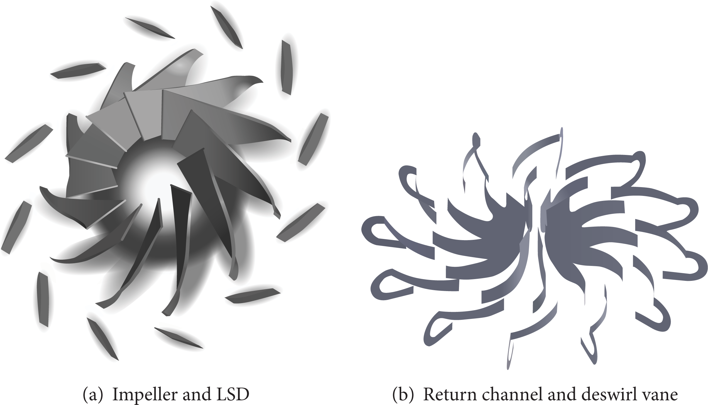
Blade geometry of impeller, LSD, and deswirl vane of the first stage.
The schematic diagram of cutting position (or splitting position) and staggered angle of deswirl vane is as shown in Figure 3.

Schematic diagram of (cutting position, staggered angle) of deswirl vane.
The compressor operates steadily at 11000 rpm. The equations used in this study include Continuity equation, Reynolds average momentum equations (rotating frame for impeller, stationary frames for the others), and Reynolds average energy equation. The physical properties (temperature, pressure, density, enthalpy, and entropy) of refrigerant R-134a are obtained from interpolation of the refrigerant properties table.
The boundary conditions used in this study are shown in Table 1.
Boundary conditions.
When the flow rate is high, the pressure markedly increases as the flow rate decreases, and setting the exit static pressure to calculate the flow rate is likely to converge. However, when the surge flow rate is approached, as the pressure-flowrate curve is nearly horizontal, a small pressure increase can greatly reduce the flow rate. Moreover, when the flow rate is lower than the surge flow rate, the pressure decreases with the flow rate, thus, setting the exit static pressure to calculate the flow rate renders it difficult to obtain result. Therefore, the outlet flow rate shall be set to calculate the exit pressure, which mode requires longer computer time.
3. Numerical Method and Meshing
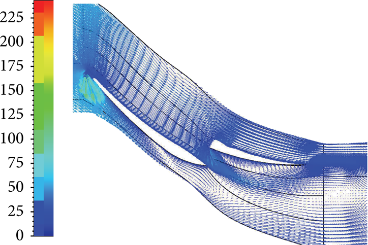
This study uses the Numeca FINE/Turbo package to calculate the flow field and performance of a compressor. The physical properties of R134a are already constructed in this software. The convective term of Reynolds average momentum equations (at rotating and stationary frames) and Reynolds average energy equation uses second-order upwind difference, the numerical iteration uses time marching to compute a steady-state solution, and the turbulence model is the Spalart-Allmaras model (suggested by FINE/Turbo). The convergence criteria are the residuals of velocities, pressure, temperature, and turbulent kinetic energy smaller than 10−5. The mesh of the computational domain is as shown in Figure 4. For a convenient view, the mesh of computational domain is reproduced as Figure 4.

The mesh system of the first stage.
The cell numbers of the grid test are 183372, 364266, 726604, and 1166056, with the result as shown in Table 2. The pressure ratio of the 726604 cells is slightly different from the pressure ratio of the 1166056 cells. This study uses approximately 730 thousand cells for all calculations.
Grid test (single row, flow rate 11.3 kg/s).
4. Results and Discussion
The compressor of this study is a 550RT centrifugal chiller. The performance of this chiller had been measured according to the test standards of ASHRAE 90.1/2011 and AHRI 551/591. The uncertainty of pressure measurement is about 0.7% and the uncertainty of mass flow rate measurement is about 3.0%. The geometry of the flow elements of the compressor is imported into Numeca FINE/Turbo package for flow field analysis and performance calculation. This study focuses on the deswirl vane of the first stage; thus, the numerical simulation only aims at the first stage. Figure 5 shows the numerical calculation is well consistent with the experimental measurement, the average error is about 2%, and the points where the pressure begins to decrease with the flow rate (regarded as the surge starting point in this study) are quite close to each other; thus, the numerical calculation of this study is sufficiently reliable.

Pressure-flowrate curve of the first stage and comparison between numerical calculation and experimental measurement.
For convenient expression, the form of the deswirl vane is represented by (cutting position, staggered angle, and second row deswirl vane rotation angle), for example, (2/3, 15, 10) (Figure 3(d)):
the 2/3 of vane length from the inlet of single-row vane is the cutting position; one row is divided into two rows;
the second row vane takes the motor shaft as the rotating center, rotated 15° clockwise;
the center point of the second row vane is taken as the rotating center, rotated 10° clockwise.
4.1. Performance Comparison of Different Staggered Angles of Deswirl Vane
Figure 6 shows the pressure ratio at different staggered angles when the cutting position is at 1/2 of the vane. The surge flow rate of a single row deswirl vane shall be about 8 kg/s, as the pressure ratio of 7.5 kg/s is lower than 8 kg/s. The pressure ratio of the deswirl vane (1/2, 7.5, 0) is a little lower than that of the single row at low flow rate, is very close to the single row at high flow rate. The surge flow rate is about 8 kg/s. Generally speaking, the difference between (1/2, 7.5, 0) and a single row is slight. However, the pressure ratio of a deswirl vane (1/2, 15, 0) is very different from the former two types, and the difference increases as the flow rate decreases. The surge flow rate is about 8.5 kg/s.

Pressure ratios of different staggered angles when cutting position is at 1/2 of the vane.
Figure 7 shows the flow field of (1/2, 15, 0) at the surge flow rate (8.5 kg/s). Figure 7(a) shows that the vaneless diffuser have recirculating flow, and the return channel has obvious flow separation; thus, as these recirculating flows connect to each other, the pressure cannot increase continuously at a low flow rate due to high pressure loss. In addition, the second row guide vane has several recirculating flows at the hub (Figure 7(b)) and the shroud (Figure 7(c)). The range of the recirculating flow at the hub outlet is very large and extends to the band channel; thus, pressure loss is further increased.

Velocity field (m/s) of deswirl vane (1/2, 15, 0) at surge flow rate (8.5 kg/s).
Figure 8 shows the flow field of deswirl vane (1/2, 7.5, 0). Figure 8(a) shows the recirculating flows in vaneless diffuser and return channel of (1/2, 7.5, 0) is smaller than those of (1/2, 15, 0). The flow fields in Figures 8(b) and 8(c) are much smoother than (1/2, 15, 0). There is only a small recirculating flow at the hub outlet, which is even smoother than the flow field of a single row (Figure 9). Figure 9(a) shows that, in the meridional flow field of the single-row deswirl vane, the recirculating flow of the return channel is apparently smaller than Figures 7(a) and 8(a). However, Figure 9(b) shows the deswirl vane has a strip recirculating flow in the downstream of the hub. The performance of the return channel of the single row is better than (1/2, 7.5, 0), and the performance of deswirl vane (1/2, 7.5, 0) is better than the single row, thus, they have equivalent overall efficiency.

Velocity field (m/s) of deswirl vane (1/2, 7.5, 0) at 8.5 kg/s.

Velocity field (m/s) of a single-row deswirl vane at 8.5 kg/s.
According to Figures 7, 8, and 9, the difference in deswirl vanes result in different flow fields of vaneless diffuser and return channel, though the impeller, vaneless diffuser, LSD, and return channel are identical. Namely, the downstream influences upstream, and the influence varies with the flow rate. At a high flow rate, the LSD, vaneless diffuser, and return channel do not have recirculating flow; thus, the variation in the flow field of the deswirl vane will not influence the upstream, just like the single row and (1/2, 7.5, 0) in Figure 6. When the flow rate decreases till the vaneless diffuser and return channel have recirculating flow, the geometry and flow field of deswirl vane influence the upstream. The pressure ratio of (1/2, 15, 0) is low, because even if at a high flow rate, a recirculating flow or stagnation flow similar to Figure 7(b) occurs in the suction surface of the second row vane, thus, the main stream cannot flow along the vane, and the effect of the deswirl is reduced. Since the tangential velocity is not completely recovered as static pressure, and the recirculating flow results in pressure loss; thus, the pressure ratio of (1/2, 15, 0) at a high flow rate is obviously lower than that of the single row or (1/2, 7.5, 0).
4.2. Performance Comparison of Different Cutting Positions of Deswirl Vane
Figure 10 shows the pressure ratio of the first stage in the case of different flow rates and different cutting positions. It is observed that when the staggered angle is 15°, the cutting position has slight influence, and the pressure ratio is apparently lower than staggered angle 7.5°, meaning the influence of a staggered angle on performance is greater than that of cutting position. Generally, staggered 15° is not a good design. (1/3, 15, 0) is similar to (1/2, 15, 0) when the flow rate is 8.5 kg/s, and there is a very large recirculating flow on the suction surface of the hub of the second row. This large flow separation resulted from the large incident angle (difference between the inlet flow angle and the inlet blade angle) of the second row. Flow separation is likely to expand as it occurs on the suction surface. The hub and shroud of (2/3, 15, 0) also have large recirculating flow when the flow rate is 8.5 kg/s. The second row vane of (1/3, 15, 0) is long, and flow separation occurs on the upstream suction surface of the second row; however, as the vane is long enough, the separation bubble is reattached in the vane downstream and will not extend into the band channel, thus, it is an internal recirculating flow. The second row vane of (2/3, 15, 0) is not long enough for the recirculating flow to be reattached; thus, the recirculating flow extends into the band channel, forming a recirculating flow crossing two flow elements, which influence on performance is not less than (1/3, 15, 0).

Pressure ratios of different cutting positions.
Figure 10 shows the pressure ratio of (2/3, 7.5, 0) at a high flow rate is almost identical to that of (1/2, 7.5, 0); however, the difference increases as the flow rate decreases, and the surge occurs in (2/3, 7.5, 0) when the flow rate is 8.5 kg/s. The flow field of the shroud of (2/3, 7.5, 0) is smooth when the flow rate is 8.5 kg/s; however, extensive recirculating flow and stagnation flow occur in the suction surface of the hub (as shown in Figure 11). Besides, there is a stagnation flow at the inlet of band channel. These make the performance of (2/3, 7.5, 0) worse at a low flow rate.
Velocity field (m/s) of (2/3, 7.5, 0) at flow rate 8.5 kg/s (hub).
According to Figures 8(b) and 11, the overlap between the first row and second row of (1/2, 7.5, 0) is higher than that of (2/3, 7.5, 0). The blade angle of the deswirl vane (included angle to radial direction) decreases from the inlet to the outlet, thus, cutting and staggering at large blade angle region make the first row and the second row largely overlap. The inflow angle at the inlet of the second row vane is inconsistent with the blade angle at low flow rate; however, as the staggered angle is not large, the fluid is squeezed into the narrow channel formed by the overlapped two rows of the vane, and flow direction is forced to be consistent with the vane; thus, the expected flow separation does not occur. The overlap region of (2/3, 7.5, 0) is small, and although there is partial guide effect, it cannot completely control the flow direction. Therefore, there is recirculating flow in suction side of the second row of (2/3, 7.5, 0). The aforesaid discussion also explains why the performance of staggered angle 7.5° is better than that of staggered angle 15°. At a low flow rate, flow separation is very likely to occur on the suction surface, staggered angle 15° results in wide overlapped channel of the first row and the second row, and the effect of forced diversion is weak; thus, flow separation is inevitable. In the case of staggered 22.5° and a low flow rate, a very large recirculating flow at suction surface of the second row vane causes the flow field highly disorderly, and the numerical calculation cannot converge; thus, this part of the results is not shown.
4.3. Performance Comparison after the Second Row Deswirl Vane Rotates
Figure 12 shows the residual tangential velocity of different cutting positions and staggered angles when the second row vane is not rotated. Figure 12 shows that the residual tangential velocity of the single row, (2/3, 7.5, 0), and (1/2, 7.5, 0) decreases with the flow rate. The tangential velocity residual of (1/2, 7.5, 0) at a low flow rate is slightly lower than the single row and slightly higher than (2/3, 7.5, 0). In general, if the deswirl vane flow field has less stagnation flow or recirculating flow, the fluid flows along the blade shape relatively, and the residual of the tangential velocity is low. The stagnation flow or recirculating flow of staggered angle 7.5° is apparently less than that of staggered angle 15°; thus, the residual tangential velocity is low.
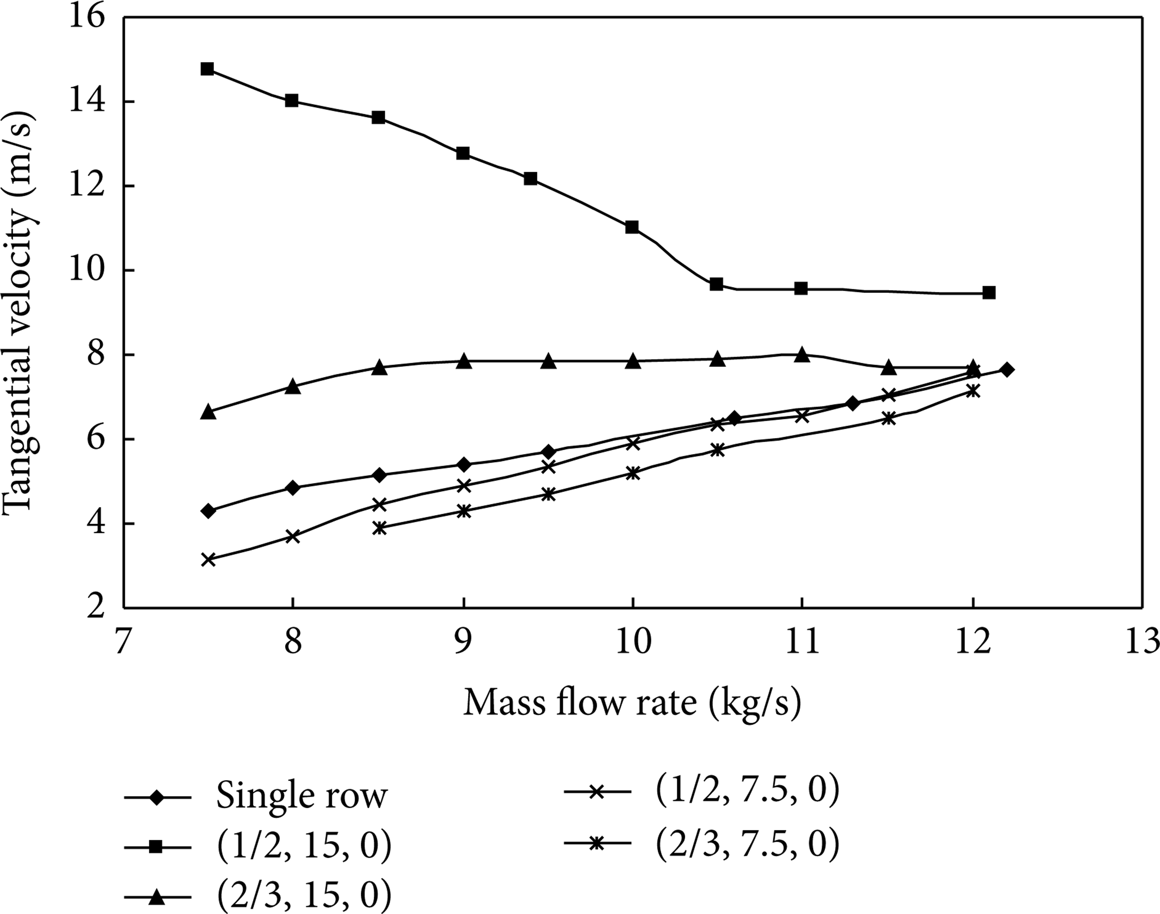
Tangential velocity residual at deswirl vane outlets at different flow rates.
The second row deswirl vane is rotated at an angle in order that the outlet of deswirl vane has higher swirl residual as the preswirl of the second stage impeller in order to postpone the surge of the second stage. Figure 13 shows the pressure ratio at different flow rates when the second row deswirl vane is rotated 10°. Figure 13 shows the pressure ratio of (1/2, 7.5, 10) is not significantly different from (1/2, 7.5, 0) at a high flow rate but is apparently lower at a low flow rate. The rotated second row vane leaves more tangential velocity when the flow rate is low; it decreases the pressure ratio of the first stage at low flow rate. The flow field of deswirl vane (1/2, 7.5, 10) is smooth. However, the surge flow rate increases to 8.5 kg/s after the rotation of the second row vane. As (1/2, 7.5, 0) converts most tangential velocity into static pressure, rendering the static pressure at the outlet of (1/2, 7.5, 0) higher, that is, higher “back pressure,” forcing the upstream vaneless diffuser and return channel to adjust the internal velocity distribution, thus, reducing their internal recirculating flow. The dynamic pressure at the outlet of (1/2, 7.5, 10) is high; thus, the outlet static pressure and “back pressure” are low, and unlikely to influence upstream velocity distribution, meaning they have large recirculating flow (as shown in Figure 14), the pressure at flow rate 8 kg/s decreases obviously, and the surge occurs earlier.

Pressure ratio of the second row vane rotated 10°.

Meridian plane velocity field (m/s) of (1/2, 7.5, 10).
Figure 13 shows the pressure ratio of (2/3, 7.5, 10) at a low flow rate is higher than (2/3, 7.5, 0), which is very different from the condition of (1/2, 7.5, 10). The deswirl vane of (2/3, 7.5, 0) has large recirculating flow at low flow rates (as shown in Figure 11); thus, the performance is poor. When the second row vane is rotated 10° clockwise, the overlap region is enlarged, and the recirculating flow on the suction surface of the second row vane disappears (as shown in Figure 15). There remains some stagnation flow; however, the flow field is obviously better than (2/3, 7.5, 0); thus, the pressure ratio is higher, and the surge flow rate of (2/3, 7.5, 0) and (2/3, 7.5, 10) is 8.5 kg/s.

Velocity field (m/s) of (2/3, 7.5, 10) at 8.5 kg/s.
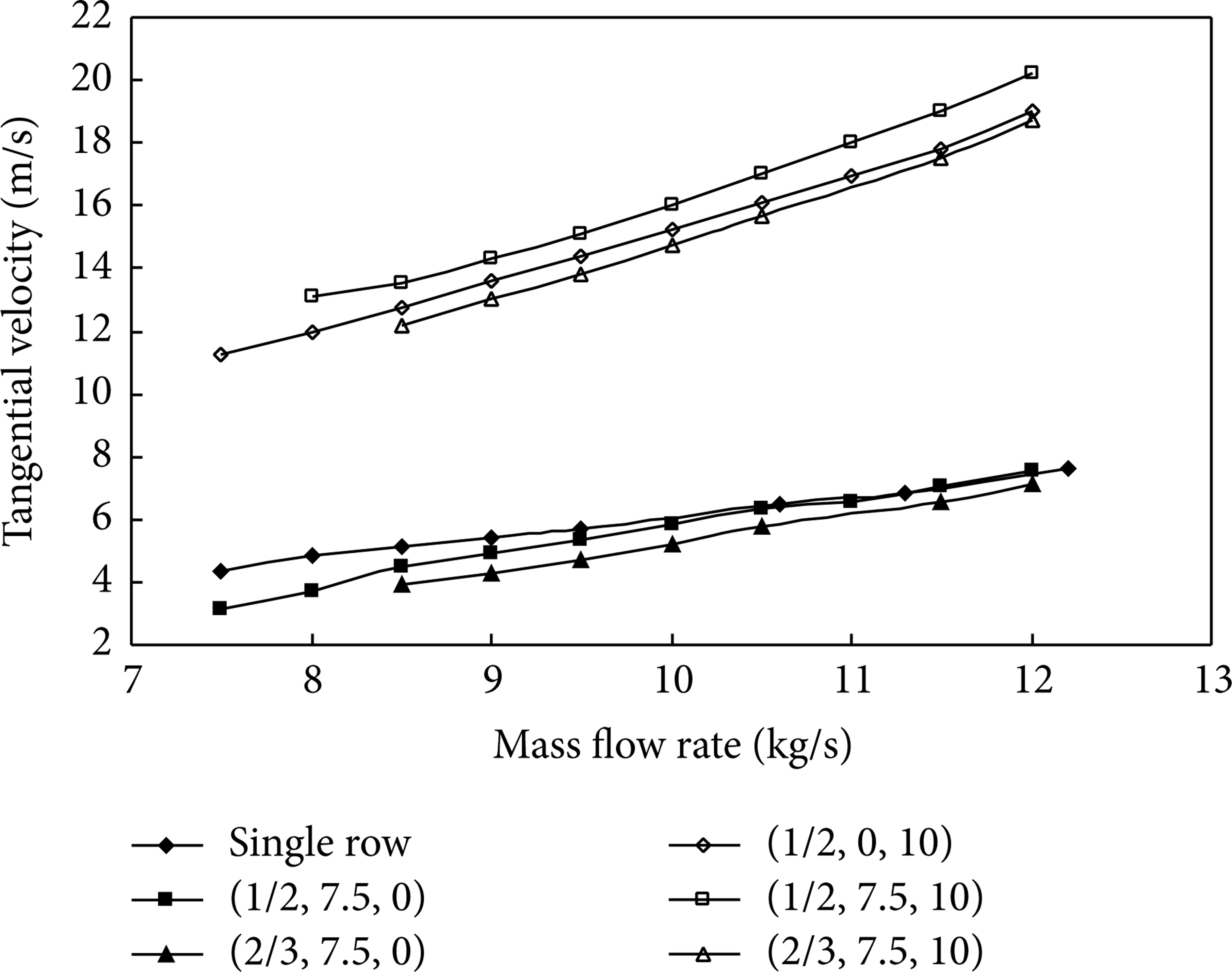
Figure 16 shows the residual tangential velocity of (1/2, 7.5, 10), (1/2, 0, 10), and (2/3, 7.5, 10), where (1/2, 7.5, 10) provides the maximum preswirl for the second stage. The second row vane of (1/2, 7.5, 10) and (1/2, 0, 10) is relatively long; thus, more tangential velocity remains from the same rotation angle. The increased tangential velocity from (1/2, 7.5, 0) to (1/2, 7.5, 10) is higher than that from a single row to (1/2, 0, 10) or from (2/3, 7.5, 0) to (2/3, 7.5, 10). The efficiency loss from (1/2, 7.5, 0) to (1/2, 7.5, 10) at a low flow rate is about 0.6%.
Residual tangential velocity of the second row rotated 10°.
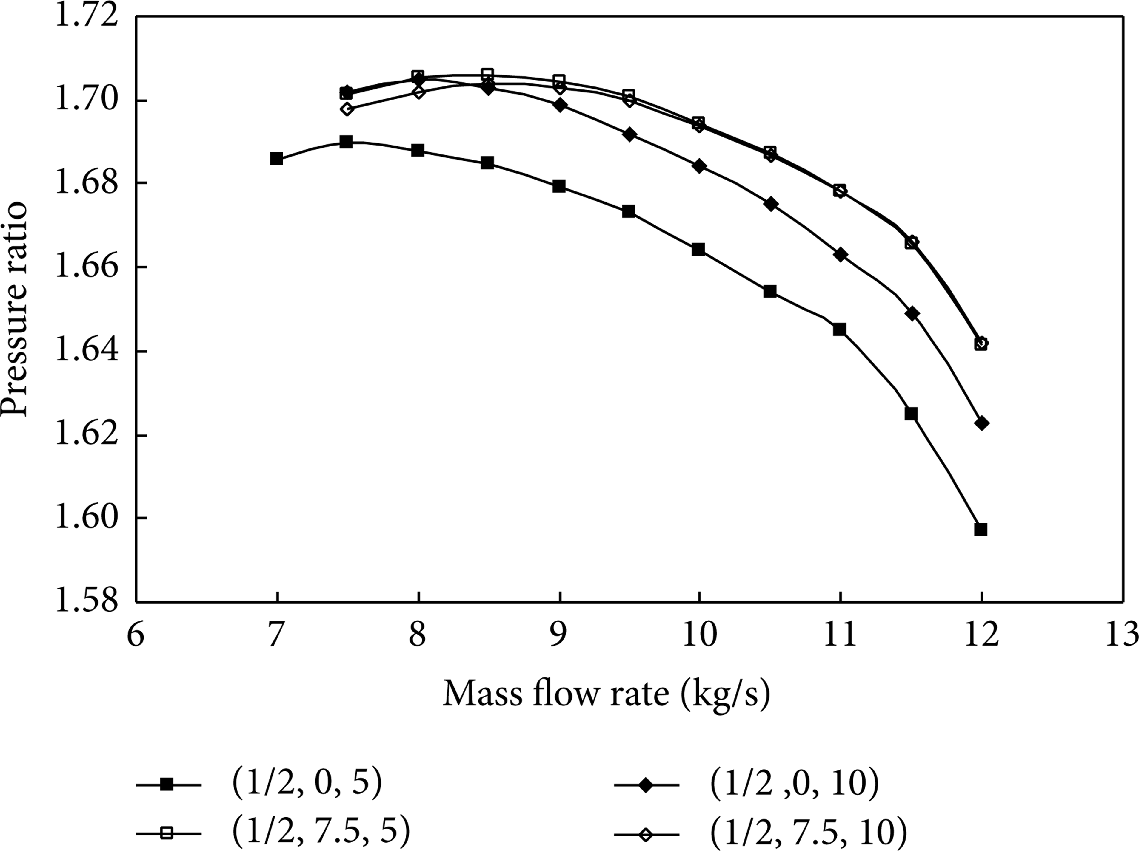
When the single row vane is split but not staggered, the second row vane is rotated 5°and 10°, with the performance of (1/2, 0, 5) and (1/2, 0, 10) as shown in Figure 17. Figure 17 shows that the performance of (1/2, 0, 5) is quite poor, as the second row rotates a small angle but not staggers with the first row, which causes geometric irregularity of the deswirl vane; thus, the deswirl vane has recirculating flow, while the upstream flow field deteriorates. However, when the second row vane is rotated 10°, a staggering-like effect occurs, and the two rows of vane overlap. The flow field of (1/2, 0, 10) at a low flow rate is much smoother than that of (1/2, 0, 5), and the pressure ratio is apparently increased, which is quite close to (1/2, 7.5, 5) and (1/2, 7.5, 10). Generally, the overall performance of staggered angle 7.5° is better than other cases. Rotating the second row vane of (1/2, 7.5, 0) effectively provides preswirl for the second stage; but the surge flow rate of the first stage increases at the same time. The IGV of the first stage may be used earlier.
Pressure ratios of staggered angles 0° and 7.5°.
Finally, there is one point about this compressor should be interpreted. During the performance test of this chiller, the second stage always surged earlier than the first stage. Therefore, this study focused on IGV for the second stage and investigated the effect of the second IGV on the performance of the first stage as the first IGV was fully opened. Nevertheless, as operating at a much lower flow rate of this compressor, both these two IGVs should be rotated simultaneously. The optimum design of the split deswirl vane depends on the interactions of all elements of the two-stage centrifugal compressor.
5. Conclusions and Suggestions
This study numerically investigates the influence of the staggered angle, cutting position, and rotation angle of the second row deswirl vane on the performance of the first stage. The conclusions are described as following.
Wherever the cutting position is, the performance of staggered angle 7.5° is better than that of staggered angle 15°, and the pressure ratio is quite close to a single row.
When the staggered angle is 7.5°, the performance of cutting at 1/2 of the vane is close to that at 1/3 of the vane and is better than that at 2/3 of the vane. When the staggered angle is 15°, the cutting position has slight influence on performance.
At a low flow rate, the geometry and flow field of the deswirl vane influence the flow fields inside the vaneless diffuser and return channel, whereas there is no influence at a high flow rate.
When the second row deswirl vane is rotated 5° and 10°, the performance of the (1/2, 7.5) deswirl vane is better than that of (1/2, 0). The preswirl is effectively provided for the second stage with a small increment of the first stage efficiency loss. Deswirl vane (1/2, 7.5) is recommended as the IGV of the second stage.
The surge flow rate of the first stage increases as a result of rotating the second row vane of (1/2, 7.5, 0).
Following this study, an optimum design of the split deswirl vane under considering all elements of the two-stage centrifugal compressor is suggested as a further research work.
Conflict of Interests
The authors declare that there is no conflict of interests regarding the publication of this paper.
Footnotes
Acknowledgment
The authors would like to thank the financial support from the Industrial Technology Research Institute (ITRI) of Taiwan.