
Abstract
The dissipated power of CPU for personal computer has been increased because the performance of personal computer becomes higher. Therefore, a liquid cooling system has been employed in some personal computers in order to improve their cooling performance. Electroconjugate fluid (ECF) is one of the functional fluids. ECF has a remarkable property that a strong jet flow is generated between electrodes when a high voltage is applied to ECF through the electrodes. By using this strong jet flow, an ECF-pump with simple structure, no sliding portion, no noise, and no vibration seems to be able to be developed. And then, by the use of the ECF-pump, a new liquid cooling system by ECF seems to be realized. In this study, to realize this system, an ECF-pump is proposed and fabricated to investigate the basic characteristics of the ECF-pump experimentally. Next, by utilizing the ECF-pump, a model of a liquid cooling system by ECF is manufactured and some experiments are carried out to investigate the performance of this system. As a result, by using this system, the temperature of heat source of 50 W is kept at 60°C or less. In general, CPU is usually used at this temperature or less.
1. Introduction
Electroconjugate fluid (hereafter, ECF) is one of functional fluids [1]. ECF has a remarkable property that a strong jet flow is generated between two electrodes when a high voltage is applied to ECF through the electrodes. By applying this strong jet flow, some systems by ECF had been developed [2]. On the other hand, by the use of the strong jet flow, a pump with simple structure, no sliding portion, no noise, and no vibration seems to be able to be developed.
Recently, the dissipated power of CPU is increasing gradually, since the performance of a personal computer becomes higher. Therefore, a liquid cooling system for CPU had been proposed and adopted in a notebook personal computer [3, 4] instead of conventional air cooling system. In a desktop personal computer and a notebook personal computer, the computer body tends to be small. Therefore, it is necessary to make the size of a liquid cooling system smaller. Then, it is required to make the pump size more compact and to develop a microchannel heat sink with high performance. In order to make the pump size more compact, typically, one-side actuating piezoelectric micropump [5] is proposed. However, a centrifugal pump driven by an electric motor is employed normally. On the other hand, there are many articles concerning a microchannel heat sink with high performance [6–10]. In the case that ECF is adopted as working fluid in a liquid cooling system for CPU, an ECF-pump with the abovementioned features can be utilized. As a result, the pumping part becomes simple compared with the pump for a conventional liquid cooling system, such as a centrifugal, a rotary, or a gear pump driven by an electric motor.
In order to realize a liquid cooling system for CPU in notebook PC by ECF, Yokota had proposed a planar ECF-pump [11]. The size of the proposed pump is A4 size (297 mm × 210 mm). The proposed pump is fabricated and the performance of the pump is made clear experimentally. In addition to that, Seo had proposed a high performance planar ECF-pump [12]. By improving electrode patterns, the size of the proposed pump becomes smaller, that is, 120 mm × 38 mm × 13 mm, and its performance is remarkable. However, the experiment to cool CPU had not been carried out by using these ECF-pumps and ECF. Therefore, it is uncertain whether a liquid cooling system by these ECF-pumps and ECF is realizable. In addition to it, to realize a liquid cooling system by ECF, it seems to be necessary to make the ECF-pump size compact and to make the pump easy to mount.
In this study, the possibility of the development of a compact ECF-pump which is easy to mount and the realization of a liquid cooling system by the proposed ECF-pump and ECF are investigated experimentally. Firstly, a tube type ECF-pump is proposed in order to make the size of ECF-pump compact and to make ECF-pump easy to mount. The proposed ECF-pump is fabricated and its basic characteristics are investigated through various experiments. Next, by the use of the proposed ECF-pump, a liquid cooling system by ECF is manufactured and the performance of the system is evaluated experimentally.
2. Tube Type ECF-Pump
2.1. Structure of Tube Type ECF-Pump and Comparison with a Substrate Multilayered Type ECF-Pump
Figure 1 shows the structure and the size of the proposed ECF-pump (hereafter, tube type ECF-pump) in this study. Figure 2 shows the substrate on which the rod-like electrodes are made and the pumping principle for the proposed ECF-pump.
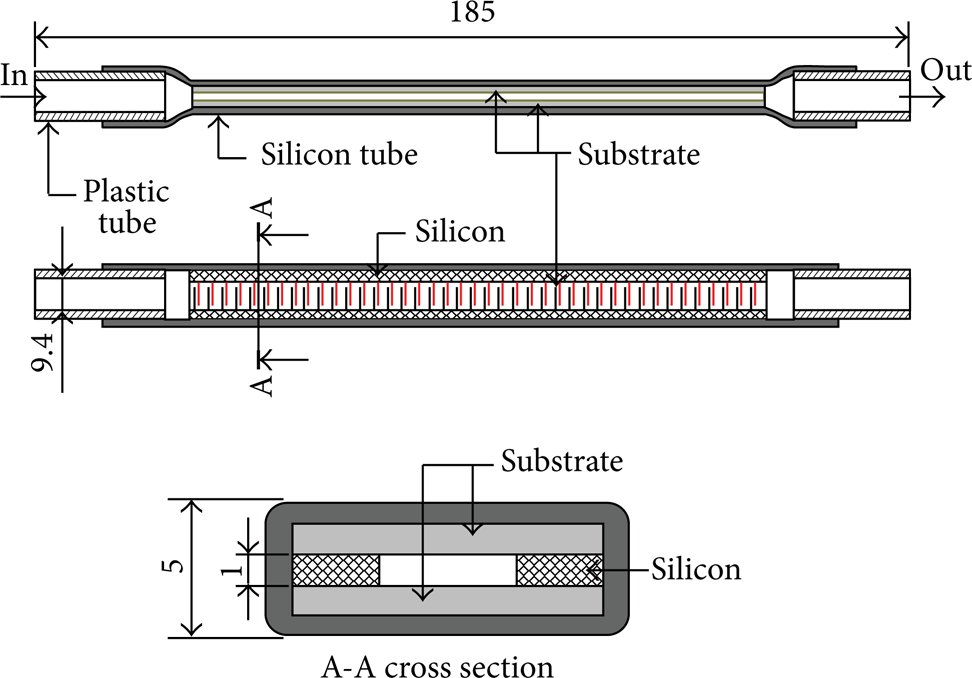
Tube type ECF-pump.

Substrate and pumping principle.
As seen from Figure 1, the size of the tube type ECF-pump is 185 mm × 9.4 mm × 5 mm. Therefore, it seems to be easy to set this ECF-pump in computer body. This ECF-pump is mainly composed of a silicon tube and two substrates arranged the rod-like electrodes. The electrode sides of these substrates are opposed and they are installed into the silicon tube. To prevent a flow of ECF of the up-and-down direction, the space of these substrates is set at 1 mm. In ECF, the jet flow generated between electrodes tends to be strong when the gap of electrodes becomes narrow. Hence, as shown in Figure 2, the space between the high voltage electrode and GND one is 0.2 mm. This value is near the limit of performing etching when the electrodes are manufactured on a substrate. Moreover, to make the jet flow into one way, the interval of a pair of the electrodes is set at 0.7 mm. Consequently, on the substrate, 69 pairs of electrodes can be arranged. The thickness of the electrodes is 35 μm. In order to reduce the pressure loss at the inlet and the outlet of the ECF-pump as much as possible, the shape of the pump inlet and outlet becomes the tapered channel.
Previously, a substrate multilayered type ECF-pump had been developed as shown in Figure 3 [13]. The size of this ECF-pump is 140 mm × 9.4 mm × 60 mm which can be mounted in 5-inch bay of a desktop type PC. This ECF-pump is mainly composed of an acrylic body, an acrylic cover, and a rubber packing and four substrates arranged the rod-like electrodes at the upper surface of the substrates. They are set at the pump body and the space between two substrates is 1 mm. To reduce the pressure loss at the inlet and the outlet of the ECF-pump as much as possible, the shape of the pump inlet and outlet becomes the tapered channel.

Substrate multilayered type ECF-pump.
The volume of the tube type ECF-pump is 8.695 × 103 mm3 and that of the substrate multilayered type ECF-pump is 2.94 × 105 mm3. Therefore, the volume of the tube type ECF-pump is about 30% of that of the substrate multilayered type ECF-pump and it is known that the tube type ECF-pump is miniaturized sharply compared with the substrate multilayered type ECF-pump. Though the length of the tube type ECF-pump is 1.3 times as long as that of the substrate multilayered type ECF-pump, the width is 9.4 mm and the height is 5 mm. Hence, it seems to be easy to arrange the tube type ECF-pump into the PC case compared with the substrate multilayered type ECF-pump. In addition to it, the tube type ECF-pump seems to be arranged into a notebook PC easily.
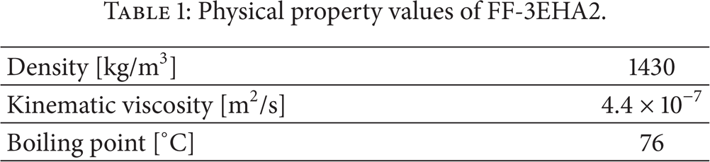
To compare the pump discharge of the tube type ECF-pump with that of the substrate multilayered type ECF-pump, experiments were carried out by varying input voltage Vin. The experimental equipment is illustrated in Figure 4. Then, the substrate shown in Figure 2 was employed. Two substrates were installed in the tube type ECF-pump and four substrates were installed in the substrate multilayered type ECF-pump. In these experiments, a gear type microflow meter was employed for measuring the pump discharge. The FF-3EHA2 was used in these experiments, which is a type of ECF. It is confirmed that the jet flow by the ECF becomes stronger. Its physical property values are shown in Table 1.
Physical property values of FF-3EHA2.

Experimental apparatus for comparison of pump discharge of each ECF-pump.
The experimental results of pump discharge Q p are shown in Figure 5. As seen from this figure, it is confirmed that Q p of the tube type ECF-pump is larger than that of the substrate multilayered type ECF-pump when Vin is less than 1.75 kV, though the tube type ECF-pump has two substrates and the substrate multilayered type ECF-pump has four substrates. Therefore, it seems to be clear that the flow is efficiently given to ECF in the tube type ECF-pump compared with the substrate multilayered type ECF pump.

Experimental results of pump discharge of each ECF-pump.
Furthermore, in the abovementioned experiment, consumption current Iin was measured. The experimental results are shown in Table 2. As can be seen from this table, it is known that Iin of the tube type ECF-pump is smaller than that of the substrate multilayered type ECF-pump though Q p of the tube type ECF-pump is larger than that of the substrate multilayered type ECF-pump or Q p of the tube type ECF-pump is almost equal to that of the substrate multilayered type ECF-pump. From this point, it seems to be clear that the flow is efficiently given to ECF in the tube type ECF-pump compared with the substrate multilayered type ECF pump.
Consumption current.

2.2. Characteristics of Tube Type ECF-Pump
Figure 6 illustrates the experimental apparatus to investigate the relation between pump discharge Q p and pump pressure P p of the proposed tube type ECF-pump. A metering orifice was installed in order to adjust the resistance to the ECF-pump. Experiments were carried out, and then both input voltage to the ECF-pump Vin and the opening area of the metering orifice were varied. In these experiments, a gear type microflow meter was employed for measuring the pump discharge and manometers were used for measuring the pressures at the pump inlet and outlet ports. As ECF, the FF-3EHA2 was used in these experiments.
Experimental apparatus.
Figure 7 illustrates the experimental results between pump discharge Q p and pump pressure P p . This figure shows that pump discharge Q p decreases almost linearly with increase of pump pressure when input voltage Vin is constant. The maximum pump discharge is about 5.0 cm3/s (300 cc/min) when Vin = 2.0 kV and P p = 0.5 kPa. The maximum pump pressure is about 6.0 kPa when Vin = 2.0 kV and Q p = 0.0 cm3/s.

Experimental results of tube type ECF-pump characteristics.
3. Liquid Cooling System by ECF and Tube Type ECF-Pump
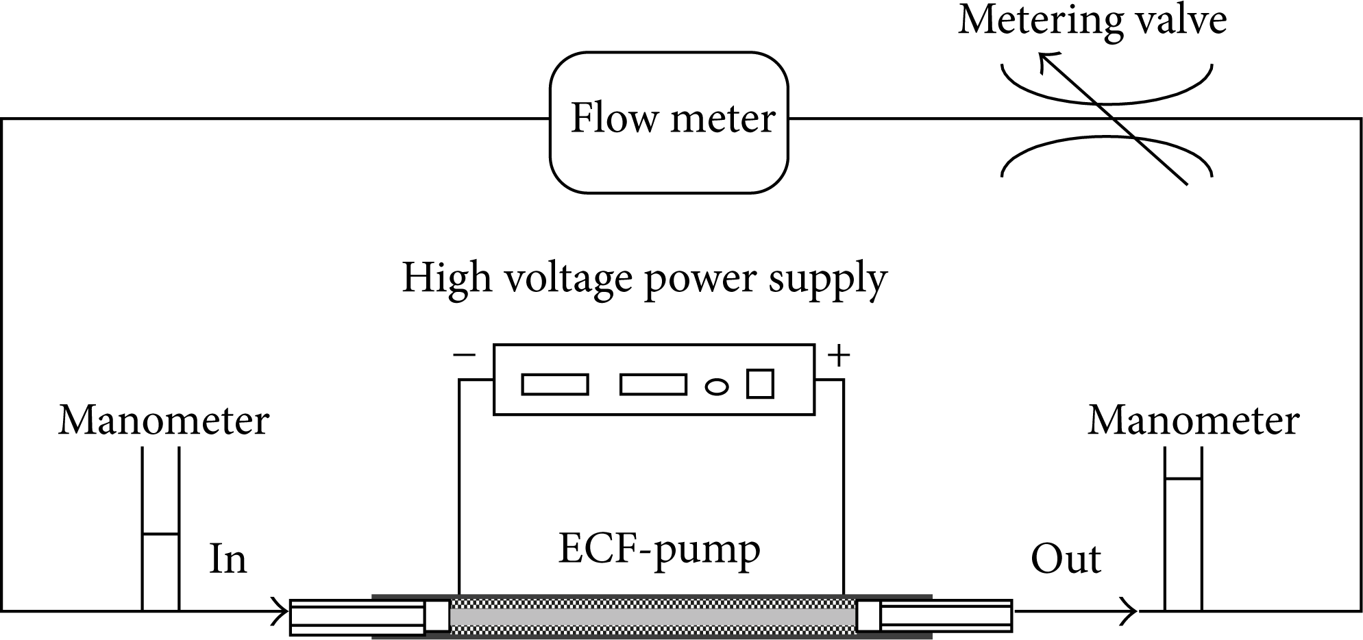
In order to confirm the possibility of realization of a liquid cooling system by the proposed tube type ECF-pump and ECF, a liquid cooling system was manufactured as shown in Figure 8.

Liquid cooling system by ECF and tube type ECF-pump.
This system is composed of the tube type ECF-pump, a liquid block to transfer heat into liquid, a heater as the model of CPU, a reserve tank, and a radiator with a fan. When a high voltage is applied to the tube type ECF-pump, ECF starts to flow. Then, ECF flows into the liquid block and the heat from the heater transfers to ECF, while ECF flows in the liquid block. The temperature of ECF flown out from the liquid block becomes high. The high temperature ECF flows into the radiator with a fan and the ECF is cooled. Thus, ECF cools the heater and maintains the temperature of the heater at a suitable value.
The purpose of this study is to make clear the possibility of realization of a liquid cooling system by the tube type ECF-pump and ECF. And this study is the first step of the development of the liquid cooling system by the tube type ECF-pump and ECF. Therefore, in this study, the commercially available water-cooled kit was employed for the liquid block and the radiator with a fan. The liquid block was made from copper with high thermal conductivity.
The heater was composed of an aluminum block and two resistances. These resistances were inserted into this block. The maximum heat quantity of the heater was 50 W, the size of the cross section of the heater was 35 mm × 35 mm, and its height was 15 mm. Generally speaking, in CPU used for a personal computer, heat occurs from the core of CPU. The heat is diffused by a heat spreader of which size is 38 mm × 38 mm in general and is transferred to a heat sink. And CPU is cooled by cooling this heat sink by air flow produced by a fan. Therefore, in this experimental apparatus, the heater, which is a model of CPU, is similar to an actual CPU at the point that the heat transfer area is almost equal.
The heat generated from the heater increases the temperature of the body of the liquid block and it is transferred to ECF flowing in the liquid block. Furthermore, the temperature of the body of the liquid block becomes high and the heat is radiated to the air around the liquid block through its surface. As a result, the temperature of the air around the liquid block is increased. In general, when this phenomenon arises within the case of a personal computer, it negatively affects other electronic chips. Therefore, to prevent this in this experimental apparatus, the circumference of the liquid block was covered with thermal insulation and the heater was cooled only by the heat transferred to ECF.
The boiling point of ECF used in this study is 76°C. Therefore, air bubbles were generated toward the radiator from the liquid block by locally boiling in the liquid block. When these air bubbles flow into the ECF-pump, electrical discharge or short-circuit will occur between the electrodes of the ECF-pump, because a high voltage is applied to ECF through a number of pairs of electrodes. By this short-circuit, the ECF-pump stop operating and the pump discharge becomes zero. Therefore, to remove the air bubbles from the liquid block, a reserve tank was installed between the outlet of the liquid block and the inlet of the radiator. In addition to it, the ECF-pump was set between the outlet of the radiator and the inlet of the liquid block. In order to connect the ECF-pump, the liquid block, and the radiator, the polyurethane tubes were used, which were 5 mm in inside diameter and was small in thermal conductivity.
By the use of the abovementioned liquid cooling system by ECF and the tube type ECF-pump, the experiments to cool the heater as a heat source were carried out. The inside of the system was filled with ECF. Some experiments were carried out, and then input voltage Vin was varied. In order to estimate the performance of the liquid cooling system by ECF and the tube type ECF-pump, thermocouples were set as shown in Figure 8. Furthermore, a flow meter was installed between the ECF-pump and the liquid block to measure the pump discharge when the heater was cooled. In these experiments, the output wattage of the heater was set at 50W which is the maximum. The rotation number of the fan of the radiator was 3000 rpm and the temperature of the circumference of the system was kept about 24°C.
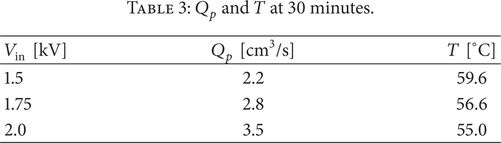
Figures 9, 10, and 11 show the experimental results with the variation of input voltage Vin to the ECF-pump. In these figures, T1 and T2 denote the temperature of ECF at the inlet and the outlet of the liquid block, respectively. And T3 and T4 denote the temperature of ECF at the inlet and the outlet of the radiator, respectively. Table 3 describes pump discharge Q p and temperature T of the heater at 30 minutes after starting the experiments.
Q p and T at 30 minutes.

Temperature in liquid cooling system at cooling test (Vin = 1.5 kV).

Temperature in liquid cooling system at cooling test (Vin = 1.75 kV).

Temperature in liquid cooling system at cooling test (Vin = 2.0 kV).
As can be seen from Figures 9–11, temperature of the heater T is converged on a steady value within 20 minutes and maintains the value shown in Table 3. From Table 3, it is known that temperature of the heater T tends to decrease with an increase of input voltage Vin, that is, an increase of pump discharge Q p . And it becomes 55.0°C when Vin is 2.0 kV. Generally speaking, in personal computers, when CPU of which electrical power consumption is about 50 W is in operation, its maximum temperature is about 70°C [14]. And then, the CPU is cooled and its temperature is kept between 50°C and 60°C. Therefore, when Vin becomes between 1.5 V and 2.0 V, namely, pump discharge Q p is kept between 2.2 cm3/s and 3.5 cm3/s, the proposed liquid cooling system by ECF and the tube type ECF-pump seems to be applied to the cooling for CPU of which electrical power consumption is about 50 W.
4. Conclusions
In this study, the possibility of realization of a liquid cooling system by the proposed tube type ECF-pump and ECF was investigated experimentally. Firstly, the proposed tube type ECF-pump was fabricated and its basic characteristics were investigated by carrying out various experiments. As a result, it is shown that the maximum pump discharge and the maximum pump pressure of the proposed ECF-pump are about 5.0 cm3/s (300 cc/min) and about 6.0 kPa, respectively.
Next, by the use of the proposed ECF-pump, the liquid cooling system by ECF was manufactured and the performance of the system was investigated with the variation of the input voltage to the ECF-pump. Consequently, it is confirmed that the liquid cooling system by ECF and the proposed ECF-pump has enough performance to cool CPU of which electrical power consumption is about 50W at suitable temperature.
Next step is to investigate the detailed design data for the proposed tube type ECF-pump. In addition to that, in order to optimize the proposed ECF-pump, it seems to be necessary to investigate the influence of the performance of the proposed ECF-pump with the shape of the electrodes arranged on the substrates. On the other hand, it seems to be important to develop the radiator without the fan because the ECF-pump is with no noise. As a result, by the use of ECF, the liquid cooling system with no noise is realized.
Conflict of Interests
The authors declare that there is no conflict of interests regarding the publication of this paper.