
Abstract
We presented the kinematical analysis of a 4-DOF hybrid palletizing robot. The palletizing robot structure was proposed and the arm model of the robot was presented. The kinematical analysis of the end robotic manipulator was given. As a result, the position, velocity, and acceleration curves as well as the maximum workspace were demonstrated by simulation in Matlab. This study would be useful for the kinematical characteristics of the 4-DOF palletizing robot in space.
1. Introduction
Employment of robots in manufacturing has been a value-added entity for the company in gaining their competitive advantages. Palletizing task is necessary to promote efficiency of picking and placing task. This is, however, one of the most monotonous and heavy laborious works in the factory. Bag stacking and unstacking are very labor-intensive work. It is hard for companies to find enough people to fill these positions.
Palletizing robot is used to implement the grabbing, handling, stacking, unstacking, and other tasks of large quantities of parts and packages in industrial processes [1]. Robots in industry can decrease the cost of labor, increase the flexibility and versatility, improve the accuracy, efficiency of production and working conditions, displace human working in hazardous and impractical environment.
With the rapid development of Chinese palletizing, packaging, and other logistics industries, the contradiction between the growing market demand and the production efficiency has put forward higher requirements to the production efficiency of palletizing equipment. Develop low cost palletizing robots has become an urgent problem of Chinese robot industry.
Recently, several studies have proposed and developed various approaches for simulating and analyzing the palletizing robot. For example, several types of composite pairs and new kinds of subchains with specific degrees of freedom were proposed [2], which provided a reference for the structural design of the hybrid palletizing robot. In paper [3], the kinematics characteristic of a kind of 4-DOF palletizing robot mechanism, the series-parallel palletizing robot mechanism that can realize three-D translation and one-D rotation, was investigated. Additionally, in order to simplify the building process of kinematics equations, the way to treat the parallel structure of the robot as a whole and to replace it by the tandem structure was used to establish the kinematics model of the robot with application of D-H, and the inverse kinematics equations were also presented [4]. A 4-DOF palletizing robot manipulator was designed to meet the needs of high-speed palletizing in logistics automation industry and the forward kinematics model and inverse kinematics were introduced [5]. The joint displacements of 7-DOF hybrid robot were calculated with a kinematics modeling method based on the ST (spinor theory) named METM [6].
The dynamics analysis of the palletizing robot was proposed. The kinetostatic mathematical model for the palletizing robot was established through the method of kinetostatic by taking the theory of D'Alembert to transform the instantaneous inertial force system into a static system based on analysis of structure and force [7, 8]. The calculative software of a palletizing robot's kinematic model is designed and established by Matlab and the force condition of key axes and key parts in the process of palletizing robot motion with the position and orientation change was presented by the calculative software [9]. In [10], the mechanical design and kinematic analysis were proposed based on a detailed algorithm.
In addition, the workspace of the palletizing robot was also studied. The kinematic model of a 5-dof hybrid parallel architecture was given in two slightly different variants [11]. The workspace is simulated based on the results of structural analysis [12]. In [13], the three-dimensional workspace maps and coordinate plane projection maps of a proposed palletizing robot were derived. The kinematics model of IRB460 configuration palletizing robot of ABB was set up based on D-H algorithm, and the three-dimensional workspace maps and coordinate plane projection maps were presented [14].
The traditional series and parallel robots are not substitute but complementary roles in the application because of the dual relationship on the structure and performance characteristics [3].
A 4-DOF hybrid palletizing robot is proposed in this paper. Its movements in the horizontal and vertical planes are decoupled with optimized structural dimensions, which contributes to the trajectory planning and workspace analysis. The position, velocity, and acceleration simulation curves of the end effector with a general input and the maximum workspace have been obtained by simulation and analysis.
2. Introduction of the Palletizing Robot
The structure of the 4-DOF hybrid palletizing robot is shown in Figure 1. It is mainly composed of a base, waist welded frame, arm, and wrist. The base connects the waist by a rotary joint of which the axis is perpendicular to the ground, which drives the robot working part to move back and forth between the production line conveyor and the stack in the vertical direction. The waist welded frame supports and drives the entire arm, through the reciprocating motions of the horizontal and vertical sliders. The arm is composed of the forward big arm, the back big arm, the connecting arm, and the forearm. The forward big arm and the back big arm are hinged by the connecting arm. A parallelogram mechanism is built up by two sets of parallel institutions which contain all of the four arms. This not only increases the stiffness of the whole arm but also enlarges the stroke. The entire arm parallel structure is a key part of the hybrid palletizing robot. The size of each link directly affects the design of the robot workspace.
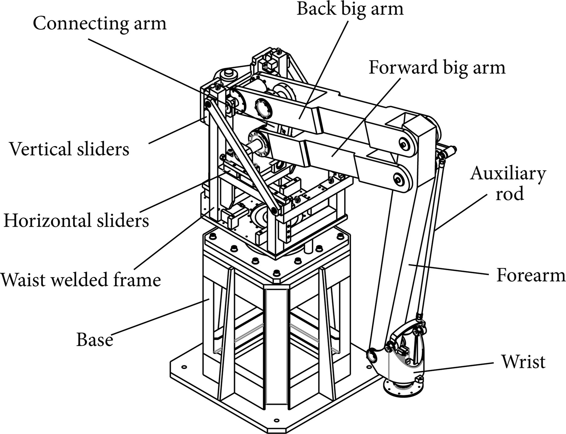
The structure of 4-DOF hybrid palletizing robot.
The wrist is connected to the forearm by a rotating shaft and the gripper connection plate to the wrist bracket by rotating joints. The gripper connection plate can connect different types of grippers, which can meet different needs of production and application. In order to keep items at a horizontal state during the handling process, a wrist translational holding mechanism which consists of two series of parallelograms is designed in the arm and wrist with the lower end fixed on the horizontal slider and the other end connected to the wrist bracket to adjust its posture.
The wrist rotation axis is perpendicular to the ground and the grabbing items are always at a horizontal state during the entire process, which simplifies posture planning and shortens the work cycle of the palletizing task.
3. Kinematics Analysis
The arm parallel mechanism is simplified into a parallelogram model as shown in Figure 2, which includes the forward big arm, the back big arm, the connecting arm, and the forearm. This mechanism has two inputs, which are movements of the horizontal slider A1 and the vertical slider A2, and one output, which is the movement of the end effector reference point P. The posture of the end effector is defined as X = [p x , p y , p z , 1] T and β = θ1 + θ5, where

The arm model of 4-DOF hybrid palletizing robot.
p x , p y , p z are coordinates of the end effector reference point P with respect to the world coordinate system X0O0Z0:
θ1-rotary variable of the waist welded frame rotary joint,
θ5-rotary variable of the wrist rotary joint.
The two rotary degrees of freedoms of the palletizing robot's waist and wrist only determine the position and orientation of the packages in the horizontal plane and have no strict requirements for the size of the mechanism. Only the positions of the horizontal sliders and vertical sliders determine the position of the packages in the vertical plane. In order to simplify the kinematical analysis of the robot, only the movement in the vertical plane of the mechanism is taken into account. The kinematic sketch of the palletizing robot is shown in Figure 3.

The kinematic sketch of the palletizing robot.
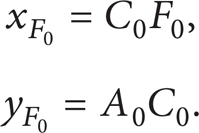
When the mechanism is in the position shown in dotted lines, the back big arm A0C0 is in the vertical position and the forearm C0F0 is in the horizontal position. Take point A0 as the coordinate origin. We analyze the motion of the end effector reference point F with a horizontal movement x of the horizontal slider D and a vertical movement y of the vertical slider A. Take AC = λAB and CF = λCE in the design of the palletizing robot. Since the quadrilateral BCED is a parallelogram, the following equations can be obtained:

to obtain

It can be proved from (2) that point D is on the line segment AF. So

That is,

When the mechanism is in the position shown in dotted lines,
It can be obtained from (4) and (5) that the position variations of point F in the x and y directions are

With the above derivation, we can draw a conclusion about the robot kinematics that the horizontal moving distance of point F is λ times that of point D when point A is fixed and point D moves along the horizontal direction and the vertical moving distance of point F is λ − 1 times that of point A when point D is fixed and point A moves along the vertical direction.
The parameter λ should be set as 6, taking account of the factors such as the actual workspace, the productive capacity and the motion error. It should be noted that the value of λ can be neither too small in order to avoid interference during the operations and expand the workspace nor too large for the sake of avoiding reduction on the operation accuracy caused by the movement error of the sliders. So we choose λ = 6 and optimize the size parameters of the palletizing robot to ensure that the robot has a higher operation accuracy and can work without interference.
4. Kinematics Simulation
The position, velocity, and acceleration curve based on Matlab simulation are shown in Figures 4, 5, and 6. The abscissa represents the time of the movement of the robot 0∼20 s.

The position curve of the end effector reference point P.

The velocity curve of the end effector reference point P.
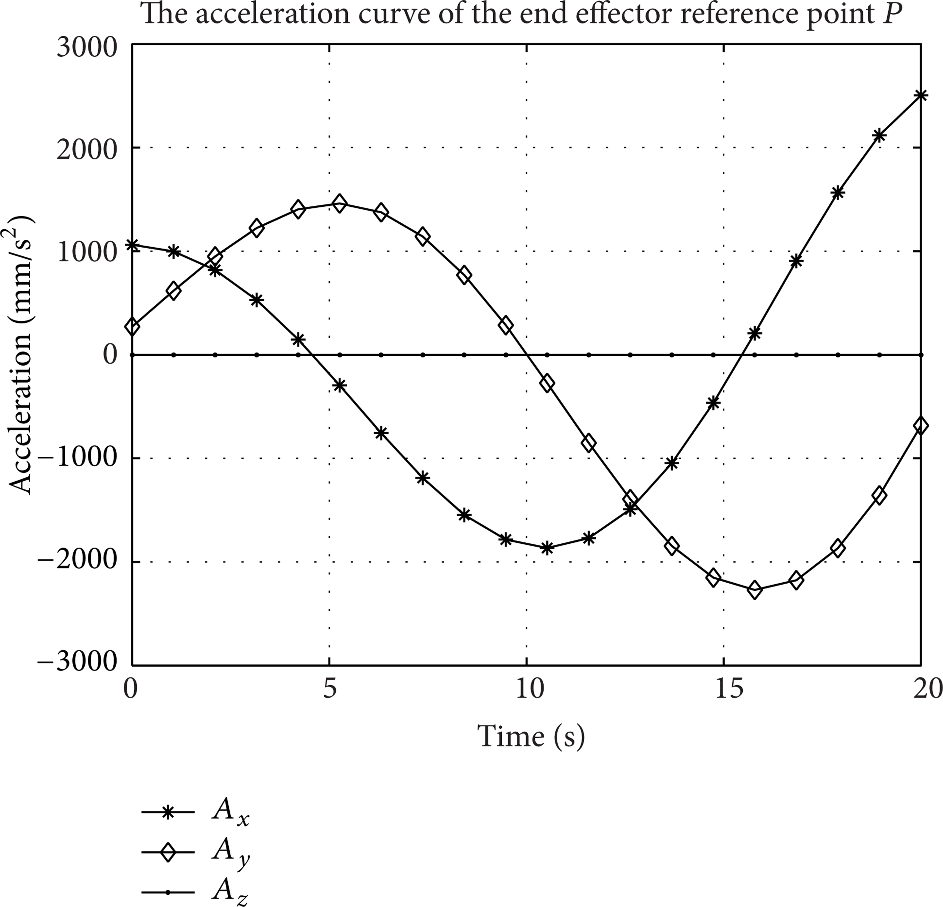
The acceleration curve of end effector reference point P.
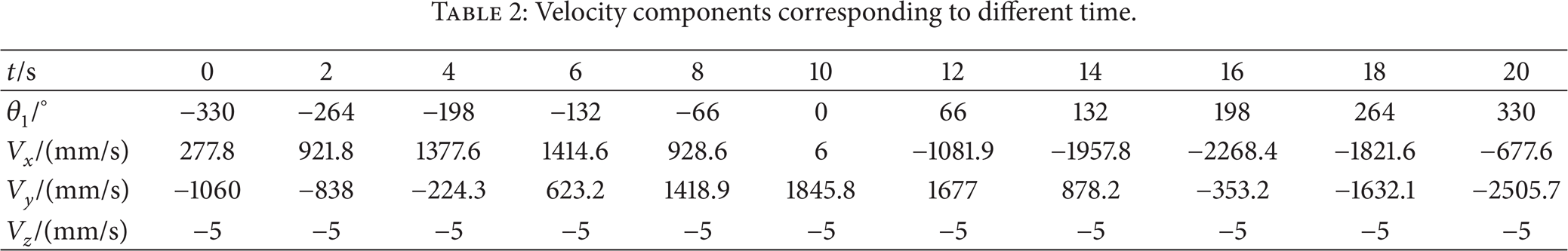
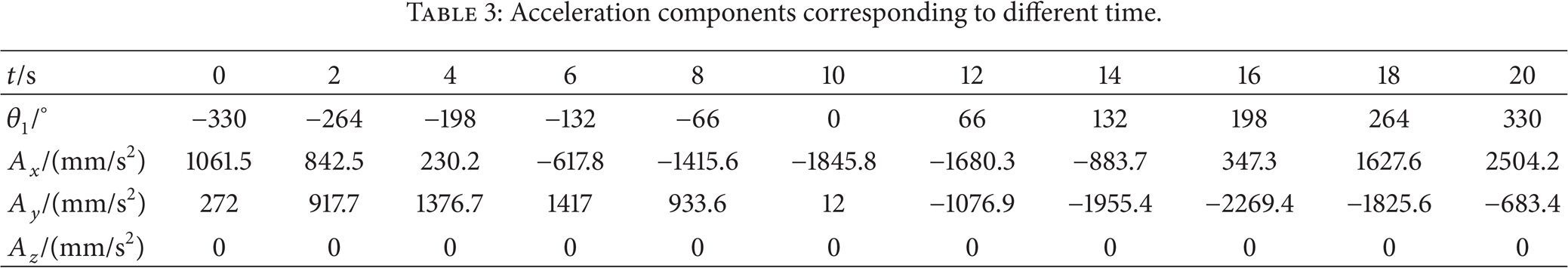
The position curve of the end-effector reference point P is shown in Figure 4, and the position components corresponding to different time are summarized in Table 1. The velocity curve of the end-effector reference point P is shown in Figure 5, and the velocity components corresponding to different time are summarized in Table 2. The acceleration curve of the end-effector reference point P is shown in Figure 6, and the acceleration components corresponding to different time are summarized in Table 3.
Position components corresponding to different time.

Velocity components corresponding to different time.
Acceleration components corresponding to different time.
5. Workspace Analysis
The robot's workspace is one of the important indices for evaluation of robot geometric features, which refers to the connection of all points the end effector can reach. The structural parameters of the robot are mainly determined by the workspace that the end effector reference point required to arrive at; therefore, the analysis of workspace is important. The limit positions of the end effector are the positions along the X-axis and Z-axis corresponding to that of the two translation joints of the robot since their movements are decoupled [15].
The technical data of the hybrid palletizing robot is shown in Figure 7.

The technical data of the hybrid palletizing robot. (a) Size of robot and (b) dynamic range.
The XOZ section view, the XOY coordinate plane projection, and the three-dimensional solid shape of the palletizing robot's workspace based on Matlab software simulation are shown in Figures 8, 9, and 10 (unit: mm).
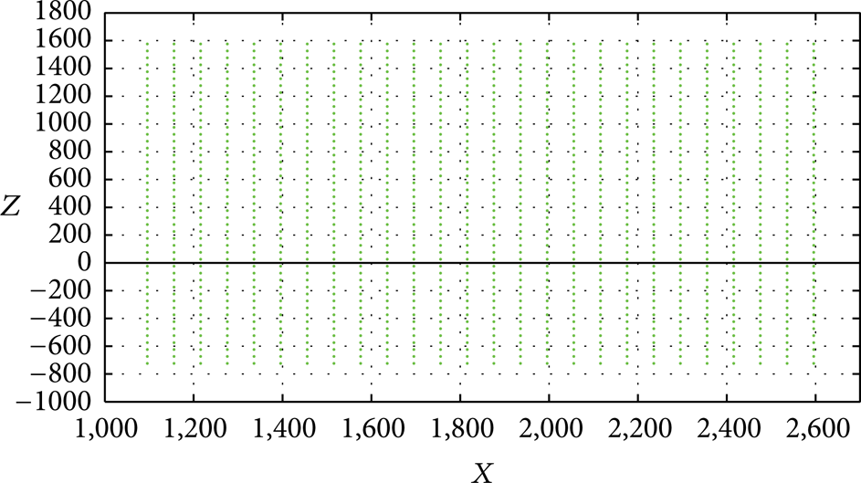
The XOZ section view of workspace.
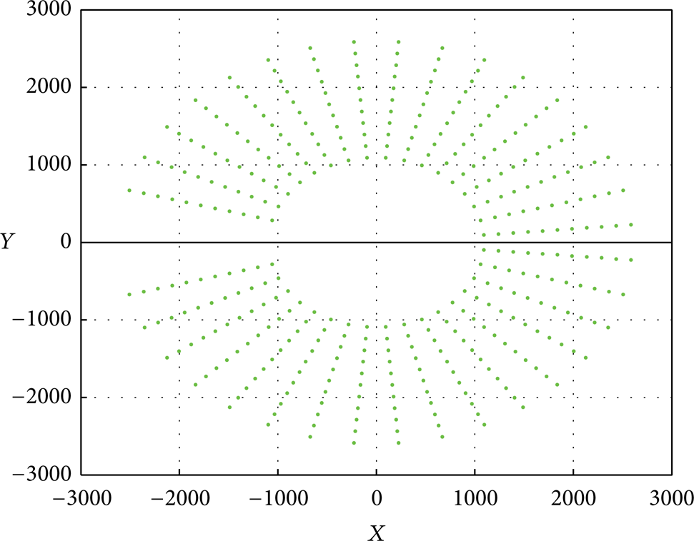
The XOY coordinate plane projection of workspace.

The three-dimensional solid shape of workspace.
The workspace of the palletizing robot is a notched cylinder and is able to meet the needs of production applications.
6. Conclusion
The kinematical analysis of a 4-DOF hybrid palletizing robot was presented. The palletizing robot structure and model were introduced. The kinematical analysis of the end robotic manipulator was given. The position, velocity, and acceleration curves and the maximum workspace were simulated, which proved that the mechanism has a good kinematic performance and provided a reference for the robot path planning and motion control.
Conflict of Interests
The authors declare that there is no conflict of interests regarding the publication of this paper.
Footnotes
Acknowledgment
This study was funded by National High Technology Research and Development Program of China (2013AA040501).