
Abstract
Ethylene supersonic combustion flow field in different injection schemes was studied numerically in the flight Mach 4. The results show that injection pressure has significant influence on the location of the separation zone and the heat release region, but the starting point of the separation region was mostly influenced by the heat release rather than by the injection pressure; the combustion efficiency of the injection schemes including two injection points is higher than that of three injection points, while the total pressure recovery coefficient of the former injection schemes is lower than the latter; excessive ethylene injected in upstream will lead to the change of free-stream flow conditions, which behaves as the inlet unstart in practical application; more ethylene could be injected in downstream to avoid the problem; on the condition of avoiding thermal choke in isolator, it is more advantageous that injection points were arranged more closely to the starting point of separation zone in upside and to the front of the cavity in downside.
1. Introduction
Hypersonic air breathing propulsion technology is the key to develop new generation low-cost high-performance transportation system [1]. Liquid hydrocarbon fuel scramjet is especially suitable to the minitype hypersonic vehicle. Liquid hydrocarbon will crack into small molecule hydrocarbon when heated; ethylene is one of the major components [2]. So ethylene could approximately substitute for heat-crack kerosene for research. For instance, in the literature [3], the cracked production was taken the place by heated mole fraction 64% C2H4 and 36% CH4; in the literature [4], heated C2H4 was adopted to calculate the booting process of AFRL SCRAMJET.
As many countries pay more attention to the hypersonic field, supersonic combustion as one of the critical technologies becomes more and more important [5]. At present, large quantity research is based on experiments. Due to the expensive cost and the strict request of experiment, numerical method becomes important for the research of supersonic combustion [6]. Yin and Yu [2] calculated the supersonic combustion of hydrocarbon/air by the fluent software with the ethylene's 11 species and 7-step reactions model reduced with ISAT algorithm and CARM (computer assisted reduction method). The result showed that the method is available. Star et al. [7] studied the mass fraction distribution in nitrogen of supercritical ethylene by numerical simulation. Taha [8] used Fluent software to investigate the supersonic combustion of ethylene and propane. Baurle and Eklund [9] in AFRL simulated the supersonic combustion of ethylene taking cavity for flame-holding. But most of the past research did not involve the supersonic combustion flow field of ethylene in different injection schemes. In this paper, the 3D Navier-Stokes equation was solved using implicit finite volume method to acquire the supersonic combustion information of ethylene. The data was compared with the experiment to demonstrate the feasibility of the numerical method used in this paper. The research result can provide some support for the design of fuel feeding system in practice.
2. Numerical Method
2.1. Calculation Model
The supersonic combustor model calculated in this paper is shown as Figure 1; it is similar to the motor used in our direct-connect experiments of the supersonic combustion characteristics of ethylene. The area of the isolator is 54.5 mm × 75 mm. A nonuniform grid of size 500 × 40 × 299 is used in the simulation. The injection orifice is resolved using 5 × 5 grid points. The grid is structured with clustering of grid points in regions of high gradients such as the near-wall region, the fuel injector, cavity, and shear layer.

Schematic diagram of the calculation model.
2.2. Numerical Method
The governing equation of discreted finite volume is solved implicitly with SST k-ω turbulence model and C2H4-O2 6-species 3-step finite rate chemical reaction model in the literature [10] with multigrid acceleration. Two-order upwind TVD (total variation diminishing) scheme is applied for spatial discretization of the convective flux terms. Viscous fluxes are approximated by a two-order central scheme. The specific heat capacities, thermal conductivity, are defined as polynomials of temperature.
2.3. Boundary Conditions
The free-stream flow, whose total temperature is 947 K and total pressure is 0.71 MPa, is a 2.1-Mach-vitiated air to simulate the enthalpy level of the typical flight conditions at the entrance of the isolator. At the injector, where the flow is sonic, stagnation pressures, total temperature, and species mass fraction are specified. At the supersonic inlet boundaries, the total and static pressures, the total temperature, and the species mass fractions are specified. At the supersonic outlet boundaries, all the variables were calculated by extrapolation from the interior. All the walls that are considered stationary, adiabatic, and no-slip boundary conditions along with standard wall functions have been used. The initial conditions were set by applying free-stream inlet conditions throughout the entire flow field.
2.4. Verification Case
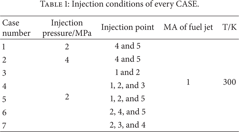
Seven cases are simulated in this study showed as Table 1. All the boundary conditions of these cases are identical except the location of injection points and that the injection pressure of case 2 is 4.0 MPa, while the rest are 2.0 MPa. Case 1 was selected as the reference case. Figure 2 shows the comparison of the upper wall pressure between calculation and our experiment in case 1. The two results are coincident in large scale especially the peak pressure. So the numerical method adopted in the paper is available and reliable.
Injection conditions of every CASE.
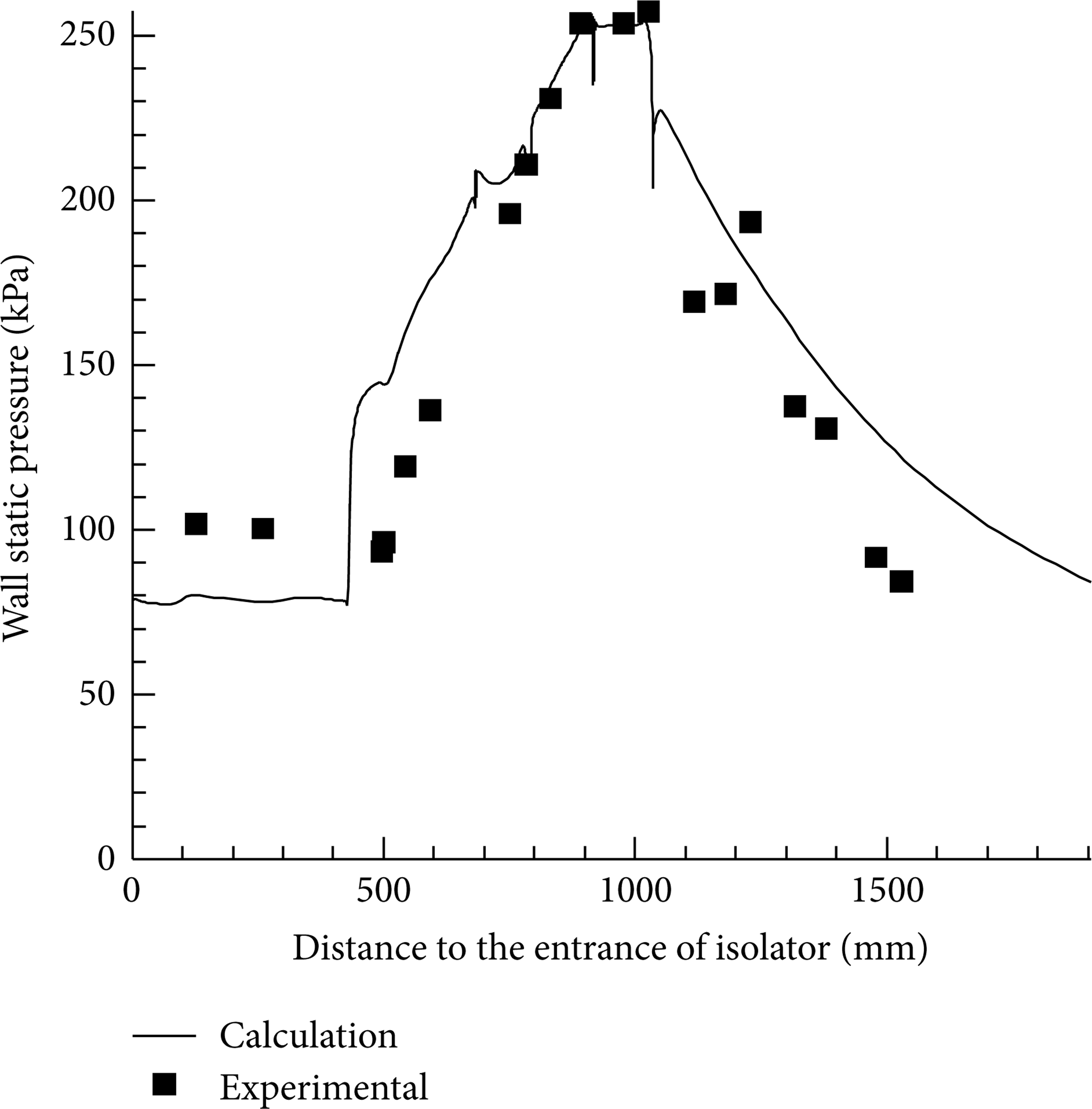
Comparison of the wall static pressure between calculation and experiment.
3. Results and Discussion
3.1. The Influence of Injection Pressure on the Ethylene Supersonic Combustion Flow Field
According to Figures 3 and 6, whether ethylene is injected at both two points or three points in 2 MPa, the high pressure due to the heat release of ethylene causes the boundary layer in upside to separate; it propagates from the separation point along the separation zone; thus the separation zone was enlarged. In the end, a large low velocity separation zone generates from the rear of isolator to the background of cavity T3. But when the injection pressure raised to 4.0 MPa, because of the strong bow wave and oblique shock wave, and the location of the the injector 4 is anterior, the boundary layer separates in downside firstly. It makes the main flow deflect to the upside to compress the boundary layer in upside, so that the separation zone cannot form in the upside although it is single side divergent. On this condition, the separation zone is located from the rear of the isolator in downside to the background of cavity B2. Although the location of separation zones is different in CASE 1 and CASE 2, the starting point of the separation zone at x-axis is the same. Figure 4 shows that the main heat release zone of CASE 1 is located in cavity T3 and its wake zone and cavity B2 and its boundary layer in downstream; but the main heat release zone of CASE 2 is located in cavity T3 and its rear whole flow passage. The two cases both form recirculation region as Figure 5 shows. But the recirculation region of CASE 2 is larger and has no divergence angle, so it has stronger transportation impact on ethylene; that part of the ethylene injected in injection point 4 was ignited to burn to release heat in the downside of the recirculation region. But the recirculation region of CASE 1 is mainly constrained in the vicinity of cavity T2. So the combustion efficiency of CASE 2 is higher than CASE 1 as shown in Table 2. In the cavity T3, the flame of CASE 1 was held as a result of the cavity shear layer and the low velocity flow in the separation zone, but the flame of CASE 2 was held by the high temperature recirculation region in cavity T3. In the cavity B2, the flame of CASE 1 is held; due to lack of oxygen, the ethylene in CASE 2 entrance in the recirculation region near the cavity B2 cannot burn completely; it was ignited in the interface between the recirculation region and main stream and organized relatively complete combustion in the subsequent main stream.
Combustion efficiency and total pressure recovery coefficient of exit.


Contours of MA distribution of CASE 1 and CASE 2 at Z = 0 mm.
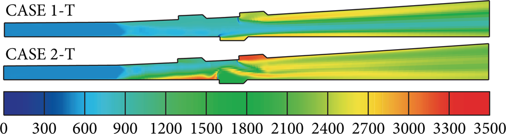
Contours of temperature distribution of CASE 1 and CASE 2 at Z = 0 mm.
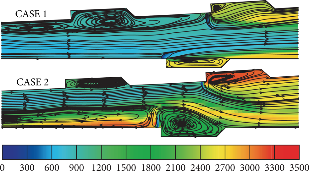
Image of streamlines of CASE 1 and CASE 2.

Contours of MA distribution of CASES 1, 3, 4, 5, 6, and 7 at Z = 0 mm.
3.2. The Influence on Injector Location on the Ethylene Supersonic Combustion Flow Field
Comparison of CASE 1 and CASE 3 in Figures 6 and 8 shows that as the injection points moving ahead upstream the separation point of boundary layer and the reattachment point both shift upstream; the separation zone of CASE 3 gets more close to the isolator. Because the injection point in downside of CASE 1 is more close to the cavity B2 than CASE 3, so the combustion efficiency of CASE 1 is higher than CASE 3. According to Table 2, the combustion efficiency of the injection schemes including two injection points is higher than that of three injection points, but it cannot make up the reduction of the total release heat as the equivalence ratio decreases. Thus the total pressure recovery coefficient of the former injection schemes is lower than the latter. Comparison of CASE 4 and CASE 5 in Figures 6 and 7 concluded that when the equivalence ratio increases, if the injector location is too close to the entrance of isolator, heat release of ethylene will lead to the change of free-stream flow conditions, which behaves as the inlet unstart in practical application. It can be verified by the abnormal total pressure recovery coefficient of CASE 4 in Table 2. So more fuel should be injected into combustor through the injectors arranged in the downstream as CASE 5, CASE 6, and CASE 7. Comparison of CASE 5 and CASE 6 in Figures 6 and 7 showed that the separation zone and the heat release region of the two cases are appropriately the same. According to Figure 8, the wall static pressure of the two cases is almost coincident in front of cavity B2, but the wall static pressure of CASE 6 is higher from the rear of cavity B2. And the combustion efficiency of CASE 6 is also higher. It is analyzed that, on one hand, although the injection point 1 is further to the exit than to the injection point 4 in which the injected ethylene has longer distance for mixing and combustion, because of the high velocity flow in the downside, the effect is not very remarkable; on the other hand, owing to the injection point 4 is closer to the cavity B2, more ethylene entrance into cavity B2 enhances the combustion and heat release. So it is better that injection point in downside is distributed more closely to the front of cavity. As to the injection point in upside, the wall static pressure of CASE 6 and CASE 7 in Figure 8 manifests that it is more advantageous that injection point in upside is arranged more closely to the starting point of separation zone on the condition that the thermal choke does not happen in the isolator.

Contours of temperature distribution of CASES 1, 3, 4, 5, 6, and 7 at Z = 0 mm.

Comparison of wall static pressure of CASES 1, 3, 5, 6, and 7.
According to Figure 6, the injection point 3 in CASE 7 is located more closely to the starting point of separation zone; its injected ethylene is distributed more closely to the mainstream and to the upstream of the low velocity separation zone than the injection point 5 in CASE 6, which results in the more sufficient mixing in CASE 7. Figure 7 shows that, owing to the injection effect of injection point 3 in CASE 7, the area of the region of heat release of combustion in the vicinity of cavity T2 in CASE 7 is bigger than CASE 6, so the action of thermal-chocking is stronger in CASE 7; the combustion of the ethylene in CASE 7 is more sufficient, which can be confirmed by the higher combustion efficiency of CASE 7 in Table 2.
4. Conclusions
In the present study, numerical simulations were conducted to study the characteristics of the supersonic combustion flow field of ethylene. The flow was solved by numerical method whose result is highly coincident with the experiment. Based on the present results, a few conclusions can be drawn.
The influence of injection pressure on the location of separation zone and combustion region is significant, but on the starting point of separation zone is negligible. The starting point of separation zone is related to the heat release of combustion in large scale.
The combustion efficiency of the injection schemes including two injection points is higher than that of three injection points, while the total pressure recovery coefficient of the former injection schemes is lower than the latter.
Although ethylene injected in upstream has longer distance for mixing and combustion, excessive ethylene injected in upstream will lead to the change of free-stream flow conditions, which behaves as the inlet unstart in practical application. In order to avoid this problem, more ethylene should be injected in downstream.
On the condition that the thermal choke does not appear in isolator, it is more advantageous that injection points were arranged more closely to the starting point of separation zone in upside and to the front of the cavity in downside.
Conflict of Interests
The authors declare that there is no conflict of interests regarding the publication of this paper.
Footnotes
Acknowledgment
This research work is supported by the National Natural Science Fund of China. The Grant ID number is 91116001.