
Abstract
The supporting plate is one of the key parts of the sonic vibration head, and the regular fatigue and fracture make the support plate be one of the most venerably damaged units, resulting in huge loss in economy and security. After analyzing the loading states of the supporting plate on sonic vibration head, the mechanical stresses of three kinds of supporting plate under different operation load cases are simulated by the method of finite element method (FEM). The effects of stress of supporting plate are studied by means of fatigue testing on actual drilling processing. The results show that the steel structures fatigue failure is caused by stress concentration and unbalance. The optimal supporting plate structure is selected by the simulation and test.
1. Introduction
As an advanced technology, sonic vibrating drilling [1] is characterized by obtaining highly original samples [2], especially in sandy and gravel soil [3]. Sonic drilling uses high-frequency resonant vibration, relatively low down-pressure, and rotation to advance core barrel and obtain sample. Water is unnecessary for the coring process [4]. The supporting plate of the sonic head, main component in sonic vibrating drill, carries the most periodic output force generated by the high-speed hydraulic motor. Therefore, the regular fatigue and fracture make the support be one of the most venerably damaged units, resulting in huge loss in economy and security.
The steel structures fatigue failure mechanisms are required to be taken into account. For this, the models of the fatigue crack growth in practical applications based on the two parameters named the stress intensity amplitude and the peak stress intensity were built by Bukkapatnam and Sadananda [5]. A finite elements program was developed to calculate the path and the associated stress intensity factors of branched cracks, validated through experiments on steel [6]. Henaff-Gardin et al. [7, 8] analyzed the cracking evolution in cross-ply composite laminates under general in-plane mechanical loading and thermal loading. Several kinds of alloy and carbon steel tested with single tensile peak overloads [9, 10] and effects of the load interaction were evaluated based on these experimental approaches [11, 12]. Since the periodic load has great effect on the plate, Dahlin and Olsson [13–16] studied the fatigue crack growth under the periodic loading based on both analytical and experimental methods. Finite element analysis is perhaps the most commonly used numerical method [17, 18]. Though the regular fatigue and fracture under the periodic output load were studied at different conditions, the supporting plate is different from the normal plate.
Our aim is to analyze the fatigue failure mechanism of the supporting plate under the sonic vibration drilling and the effect of stress of supporting plate by using fatigue test on actual drilling processing. The optimal supporting plate structure is selected based on the simulation and test to increase the life of the sonic vibration head.
2. Methodology
2.1. Structure of Sonic Head
Two high-speed hydraulic motors, driving two eccentric shafts in the same weight, respectively, are installed on the sonic head. Designed with an eccentricity of e, the two hydraulic motors rotate in fully opposite directions with an angular acceleration of w. The wholly horizontal force will be mutually offset. But the axial force will be overlapped when both the initial phase and the w are simultaneously the same (Figure 1). The axial resultant force can be expressed as follows:

The principle of sonic drilling processing.
Resonance will occur when the excitation is approximately equal to the natural resonance. The energy generated from the resonance will be transferred along the drill rod to the bit, causing the soil around to be liquefied [19]. This is greatly instrumental to the further drilling. Meanwhile, a plastic inner tube inside of the drill rod is installed to help sample and the drill rod protect the bole-hole wall by avoiding the erosion caused by the contact with drilling mud. Additionally, this measure also performs well in keeping the original layer shape of the soil.
A brief configuration for the sonic head is pictured in Figure 2. On the supporting case (1) are fixed the isolators and vibration body (3) by two pairs of bolts (2). The required support and bit pressures are provided by the chain through the supporting case. To avoid possible accidents caused by the fall of the isolators, we settled a baffle (4) under it. However, due to the periodic vibration acting on the support plate below, the supporting case becomes the easiest unit to be damaged.

Brief structure of the power unit.
2.2. Models for Finite Element Simulation
The supporting plates consist of steel rigid. Three different models were designed with the same basic size of 300 × 300 × 420 mm and 10 mm in thickness. Specifically, in comparison to the original model (model A, Figure 3(a)), a 10 mm steel plate was settled on the support (model B, Figure 3(b)) and the thickness of the support itself was increased up to 25 mm (model C, Figure 3(c)).

Support units on the drive head.
The material of the support was Q235 steel. Its yield stress is 235 MPa and ultimate tensile strength is 500 MPa. The elastic modulus and Poisson ratio of Q235 steel are defined as 2.0E11 and 0.3, respectively. A model of SOLID285 was optioned for the support unit. In terms of the grid with sides of 5 mm, it was randomly divided. As a result, there were 64, 312 units and 64,258 nodes in mode A (Figure 4(a)), 65,548 points and 65,602 units in mode B (Figure 4(b)), and 42,615 points and 42,654 units in mode C (Figure 4(c)).
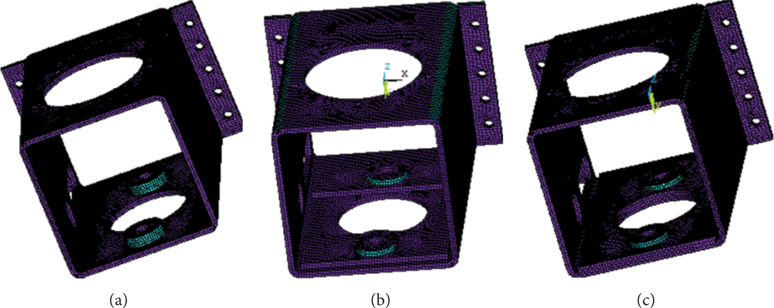
Finite element models.
The stress distribution of the two isolators was performed in this paper. Zero displacement constraints vertical to X-axis were added to all the coordinates from −150 to 150 on Z-axis and X-axis, respectively. Although the axial and the radial forces acted on the isolators simultaneously, the radial force was so little that it was neglected in comparison to the axial force. The axial force changed in accordance with a sine with a peak of 90 KN. Because the forces of the two isolators change at the same time, a sine load vertical to Z-axis was put on the isolators.
Two different loading styles were used in the further analysis. Static press, in the form of surface force, was imposed on the isolator; on the other hand, transient force was orderly exerted in a node group (Table 1).
Load on the supporting plate.

Table 1 plots that when the θ are 30, 45, and 90, the loads are all positive; when θ are 210, 225, and 270, the loads are all negative. Additionally, the positive and negative loads are correspondingly equal.
2.3. Experiment Methods
When the sonic head worked, three main periods occurred: start-up, recurrent vibrating, and stop. During the periodic vibrating, the exciting force periodically appeared. Before reaching the supporting case, the load was weakened by the isolators and bolts. Consequently, the load acted nonperiodically. Moreover, in a limited range of load, the recurrent was fluctuated. However, during the start and stop, the load on the support periodically increased and decreased (Figure 5). In order to figure out why the support broke, its micromorphology was carefully observed.
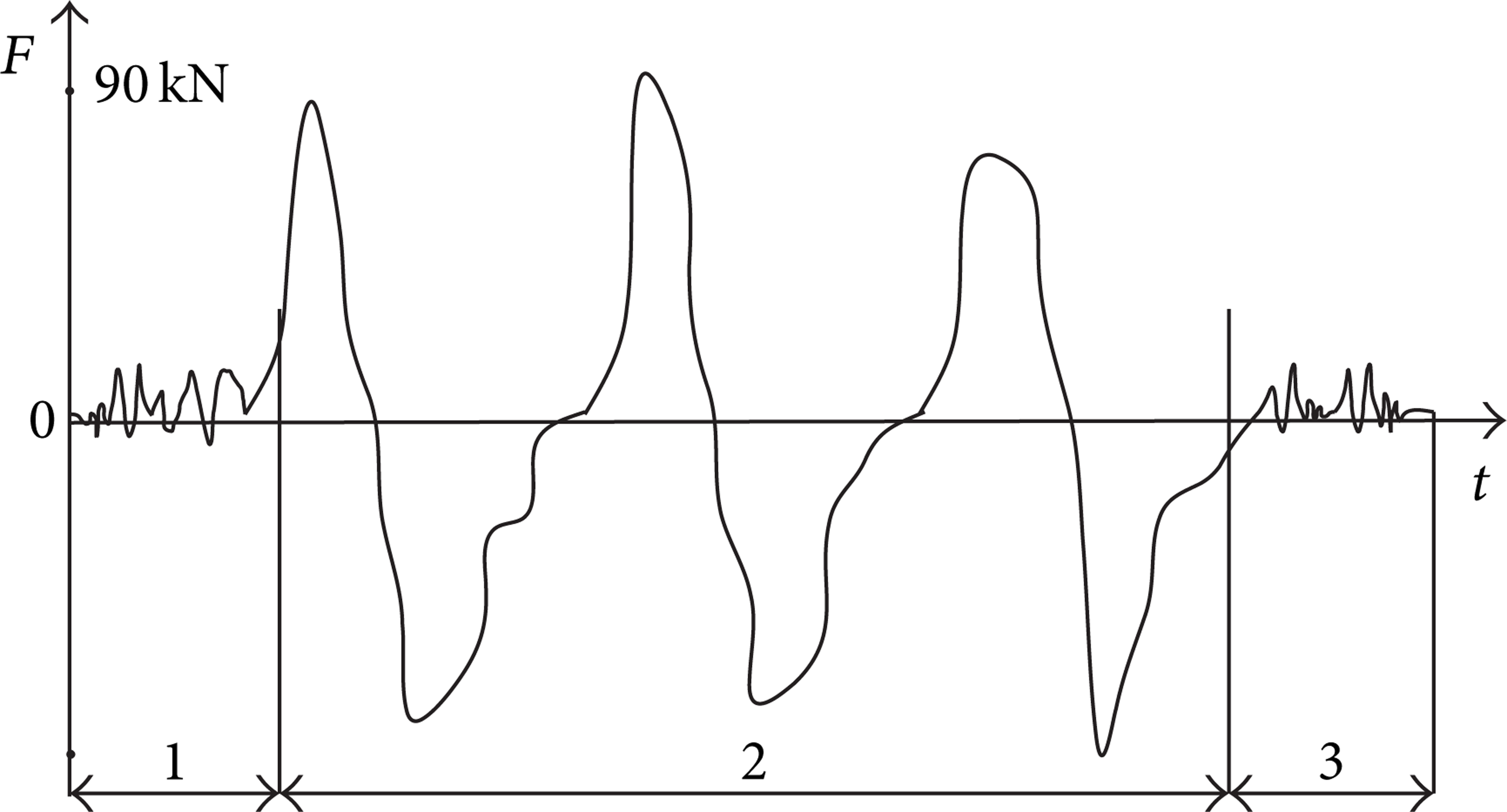
Changing laws of the single variable loads. 1: starting phase; 2: vibrating phase; 3: stopping phase.
3. Results and Discussion
3.1. Static Finite Element Stimulation
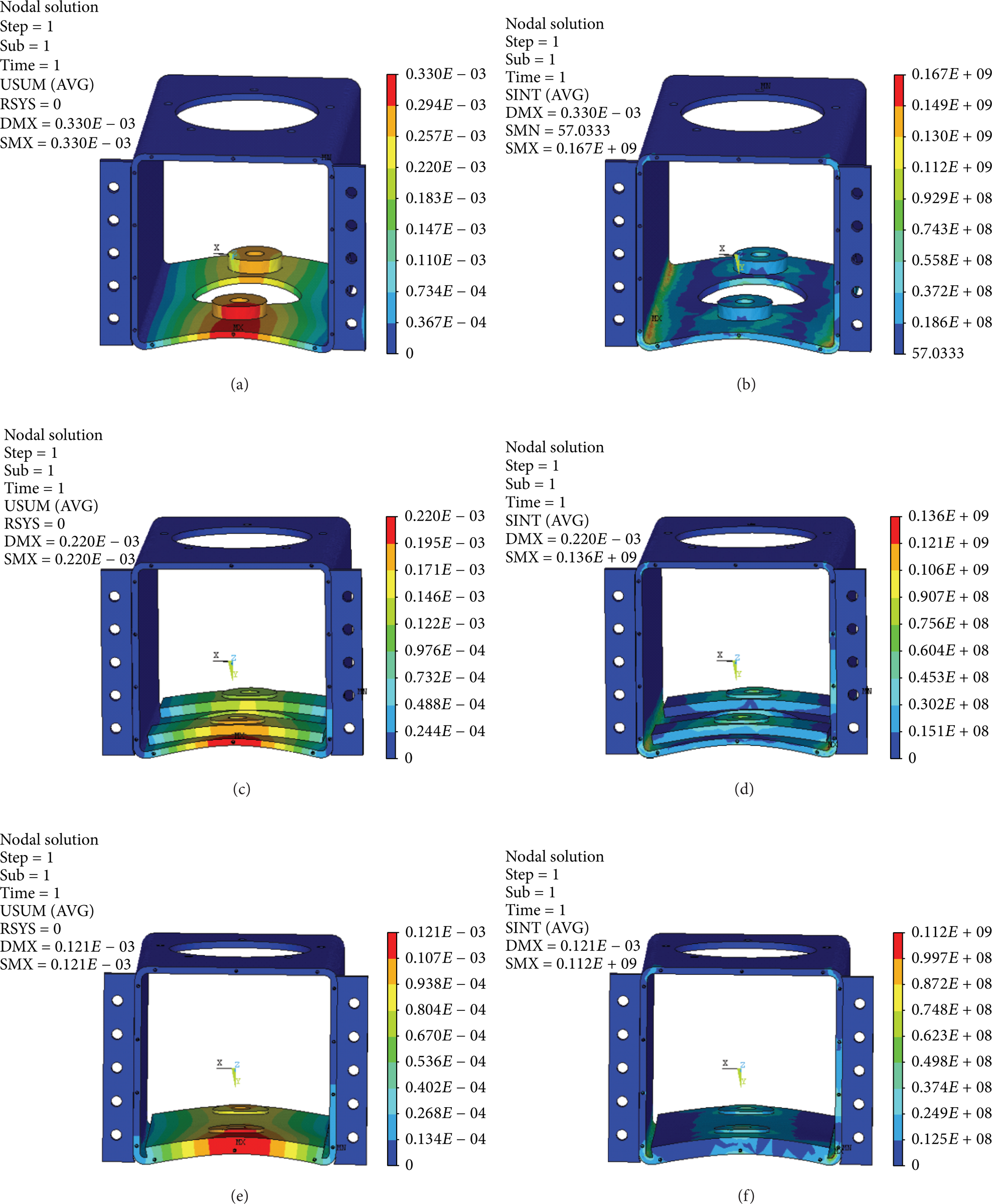
Displacement and stress plots of the internal surface are performed in Figure 6. In the light of Figures 6(a), 6(c), and 6(e), the maximum displacements of 0.22 mm (model A), 0.34 mm (model B), and 0.68 mm (model C) are observed, respectively, in the three plots. Moreover, all the maximum displacements symmetrically occur at the round ring isolator, characterized by the gradual decrease from the center to the around of the supporting plate.

Stress distribution and displacement of the external surface.
In the light of Figures 6(b), 6(d), and 6(f), the maximum stresses of 302 MPa (model A), 180 MPa (model B), and 125 MPa (model C) are all observed, respectively, at the joint between the support and the side plate. Additionally, the stress is inversely proportional to the distance away from the isolators.
Figure 7 plots the stress distribution and displacement of the internal surface. In comparison to Figure 6, observed along the central hole, a maximum stress of 112 MPa is smaller. The changing laws of the support on both sides are accordant. The maximum displacement is also observed at the joint. Moreover, the stress along the tiny hole is less than the stress at the root of the isolators.
Stress distribution and displacement of the internal surface.
3.2. Dynamic Finite Element Analysis
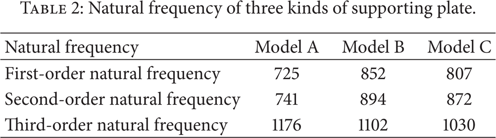
The dynamic simulations of the sweep frequency by the block Lanczos method were implemented according to the vibration frequency from 0 Hertz to 2000 Hertz by setting 10th order modes. The multiorder natural frequency is shown in Table 2. Three supporting plates will not cause resonance because the minimum first-order natural frequency is 725 Hertz, which exceeds the vibration frequency of sonic drilling (200 Hertz) greatly.
Natural frequency of three kinds of supporting plate.
According to the results of the static finite element stimulation, the maximum displacements or stresses occurred at the points of A, B, C, and D on supporting plate, as shown in Figure 8, which were selected to observe the peak displacements and the peak stresses within the working vibration frequency by harmonic response analysis.

Typical points for harmonic response analysis.
The damping ratio of the supporting plate was defined as 0.02 according to the mechanical properties of the steel Q235. The solver used the full algorithm and the completely free output of the phase and amplitude. When the peak axial is 90 KN, the peak stresses and the displacements of the typical points under dynamic FEA with the working vibration frequency (0–200 Hertz) were shown in Figure 9.

Peak stress and displacement of typical points under dynamic FEA.
In the light of Figures 9(a), 9(c), 9(e), and 9(g), the maximum displacements occurred at the point of D on the three kinds of supporting plate models, and the maximum displacements of the modes A, B, and C decrease orderly. While, in the light of Figures 9(b), 9(d), 9(f), and 9(h), the maximum and the minimum stresses occurred at the points of C and B, respectively, on the three kinds of supporting plate models, the maximum displacements of the modes A, B, and C also decrease orderly. The displacements and stresses are approximate at the points of A and C or the points of B and D.
The maximum stresses are 330 MPa and 325 MPa at the points of C and A, respectively, which are less than the ultimate tensile strength (500 MPa), and the displacements of these two points were so small that the local strength is safe enough. While, at the points of B and D, the stresses reach 188 MPa with the displacement of 2.39 mm, which does not exceed the yield stress (235 MPa). Under fatigue alternate load, the local plate is so easy to cause fatigue crack.
3.3. Fatigue Test Results
Field practice was performed on the sonic head for about 1000 hours. As shown in Figure 10, the macrostructure photo indicates that the fracture occurs under the common supporting plate, such as the points of B and D. Figure 11 shows that mode B also fractures along the aperture direction.

Macrophotograph of mode A.
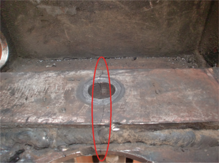
Macrophotograph of mode B.
Tested by mechanism, chemical composition, and microstructure analysis, none of the material defects has been found. Judging from the fracture arcing along the thick direction of the support as shown in Figure 12, a layered fracture happens. The even and sudden fractures indicate that the support can not bear bigger vibrator when it comes to some certain extent. It is the working load that results in fatigue fracture.

Macrophotograph of the fracture.
4. Conclusion
The peaks of the stresses are all reached at some points around the lateral side under the support. Relatively, the stress around the bolts is bigger and stretches out along the central path between the two holes. The maximum amplitude is observed at around the bolts and the amplitude also spreads out the space between the two holes. Tested by the photo from the whole, the most vulnerable region for the possible fatigue is in the place where maximum amplitude occurs.
As for the stress of the two bolts, it is virtually the same in degree and distribution law. However, the different amplitudes lead to an advanced crack of the hole. Judging from the whole picture, the crack occurs firstly in the surface of the support and gradually develops in depth, which causes the entire break in the end.
In the light of the stimulation, the laws of displacement and stress are the same. Specifically, when the loading becomes bigger, however, the maximum stresses that modes A, B, and C can, respectively, hold decrease orderly. The result also shows that mode C performs the best among the three.
The maximum stresses occur at the points of C and A. They are faultless with small displacements. While at the points of B and D on the local plate, the maximum stresses approach the yield stress with maximum displacement. Consequently, a fracture occurs under the fatigue alternate load. So we conclude that the displacement is an important factor to fatigue crack failure. This failure can be weakened by appropriately thickening the supporting plate and reducing its length and width as well as any other measures that can decrease the vibration displacement.
Conflict of Interests
The authors declare that there is no conflict of interests regarding the publication of this paper.
Footnotes
Acknowledgments
This work is supported by National Natural Science Foundation of China (no. 51004086), the Research Fund for the Doctoral Program of Higher Education (no. 20100022120003), Beijing Organization Department Outstanding Talented Person Project (no. 2013D009015000002), the Fundamental Research Funds for the Central Universities (no. 2652011273), and the Open Funds of Key Laboratory on Deep Geo-Drilling Technology, Ministry of Land and Resources (Grant no. NLSD201210).