
Abstract
A micro-TEHL finite line contact model for a helical gear pair is developed by considering sinusoidal waviness on tooth surfaces. Effects of working conditions, the amplitude, and the wavelength of the waviness roughness on the lubrication performance are studied. Results show that surface roughness has a significant influence on the pressure, the temperature, and so forth. The pressure within the nominal contact zone for a rough-surface case fluctuates around the smooth-surface solution. For the working conditions studied, at local area within the contact zone, the maximum pressure may be 50% higher than the smooth-surface result. The film contraction at the outlet zone becomes more remarkable. The film temperature also fluctuates regularly. As the amplitude of the roughness increases, the local pressure within the nominal contact zone increases while the minimum film thickness decreases. As the wavelength of the roughness decreases, the local pressure and the temperature within the nominal contact zone increase while the film thickness decreases. Effect of wavelength on the lubrication performance is more evident along the rolling speed direction than along the contact line direction.
1. Introduction
Normally for gears, the tooth surface roughness is with the same order of the minimum film thickness, which means the surface roughness effect on the lubrication performance of gear pairs is nonnegligible. Specifically at a low-speed, heavy-load case, direct asperity contacts may occur within the nominal contact zone, which would affect the pressure distribution, the friction, and the stress distribution significantly. Research on lubrication performance of gear drives has been conducted in decades. Martin applied the Reynolds equation in the lubrication analysis of spur gears [1]. Wang and Cheng studied the effect of dynamic load caused by the tooth profile deviation on the film between engaged gear pairs [2]. Zhang and Hua obtained the transient elastohydrodynamic lubrication (EHL) solution for a spur gear pair [3]. Wang et al. studied the thermal effect on the spur gear lubrication problems [4]. Recently, Li and Kahraman [5] and Liu et al. [6] used different models to study effect of tooth surface roughness on the pressure distribution and the film thickness of the engaged spur gear pairs. Liu et al. also studied the effect of dynamic load on the lubrication performance of spur gear drives considering the transient squeeze effect [7]. In the mentioned work the models are assumed to be line contact. This is fair for the spur gear pairs; however, when it comes to the helical gear pairs, problems would occur since, along the tooth width direction, the contact condition varies. The finite line contact model has been proposed by P. Yang and P. R. Yang for simulating helical gears and other components [8]. Zhu et al. used a similar finite line contact model to simulate a helical gear pair and investigated effect of the working conditions on lubrication performance of the engaged gear pair [9, 10].
In the past few decades, there have been two prominent approaches in the study of mixed-EHL or mixed-TEHL, stochastic and deterministic modeling. The stochastic modeling does not give any detailed local information. So, the deterministic modeling has been widely researched. A significant advancement in full-scale deterministic modeling of mixed-EHL has been proposed by Hu and Zhu [11]. Based on the Hu-Zhu's work, Liu et al. [12] obtained the transient temperature distribution in the point contact of mixed lubrication. Holmes et al. [13] presented a mixed-EHL model for point contact using coupled elastic and hydrodynamic equation. Venner et al. [14] studied the starved EHL circular contacts with a harmonic waviness on the surface. Yang et al. [15] investigated the influence of regular sinusoidal surface waviness direction on the lubrication with the thermal EHL model. Ren et al. [16] proposed a novel 3D line-contact mixed-EHL model (3D L-EHL); based on the 3D L-EHL model, they studied the effect of 3D sinusoidal and digitized machined surfaces on the lubrication.
Based on the development of mixed lubrication theory, the gear lubrication with surface roughness has been extremely investigated in the past three decades, especially for the spur gear. According to the load-sharing method, Akbarzadeh and Khonsari [17] predicted the performance of spur gears with provision for surface roughness and discussed the shear thinning for gear lubrication. As a development work of Holmes et al. [13], Evans et al. [18] studied the mixed lubrication for spur gear using roughness measurements and discussed the effect of slide-roll ratio and lubrication viscosity on surface fatigue. Li et al. [5, 19, 20] systematically investigated the mixed-EHL of spur gear and proposed a tribodynamic model for spur pairs. Bobach et al. [21] studied the influence of surface roughness and gearing geometry on the involute spur gears lubrication. Sharif et al. [22] also presented an analysis of mixed lubrication and investigated the effect of lambda ratio in lubricated gear tooth. Han et al. [23] firstly obtained the film parameters and friction coefficient by using the load-sharing concept for helical gear pairs and discussed the effect of surface roughness and working condition on the lubrication. Serest and Akbarzadeh [24] also proposed an efficient mixed-EHL model of helical gear using the load-sharing concept and studied the influence of the speed, load, and surface roughness on the friction coefficient and film thickness.
As mentioned above, the issue of gear lubrication has been widely researched. The researchers have obtained many beneficial conclusions for spur gear lubrication with the line contact model. However, the information about the helical gear lubrication is limited, especially for mixed-TEHL of helical gear with the deterministic modeling. The authors have already proposed a TEHL finite line contact model for a helical gear pair [9, 10]. This paper is an extension of work and focuses on the micro-EHL problems of a helical gear pair with regular tooth roughness. The main purpose of this paper is to obtain the information of surface roughness and working condition influence on the helical gear lubrication.
2. Mathematic Model
2.1. Geometrical Analysis
Figure 1 shows the geometry of the helical gear pair contact. At each engaging moment, the contact can be assumed as two cones with opposite directions contacting with each other. The rotational axes of the two cones are N1N1′ and N2N2′, respectively, while the contact line is K1K1′.
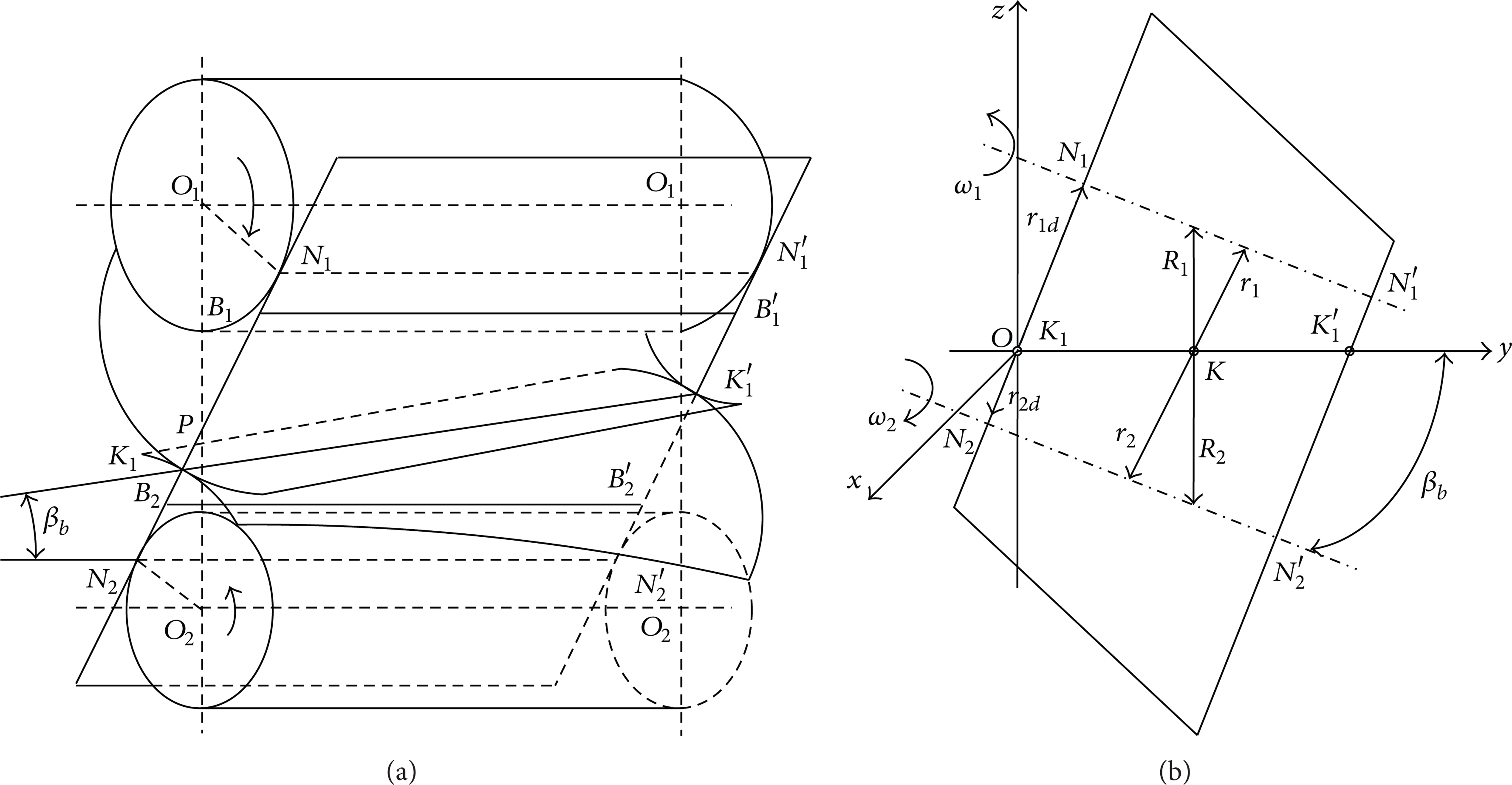
A pair of meshing helical gears.
As shown in Figure 1, the length of contact line varies continuously during the meshing cycle. Then, the radius r1, r2 along the contact line and the equivalent radius r K in the direction of entraining motion are

So, the rolling velocities u1, u2, the entrainment velocity u e , and the slide-roll ratio velocity ξ can be expressed as

In reality, almost every gear has certain amount of tooth modification, such as crown and tip relief. In this paper, we focus on the effect of surface roughness on the lubrication performance. So, the tooth modification has been neglected. However, in order to avoid the occurrence of stress concentrations at the end of contact line K1K1′, the ends of contact line are modified with dub off. The modified shapes are similar to those shown in [8].
2.2. Governing Equations
2.2.1. Constitutive Equations of Fluids
Normally the contact pressure for a gear pair is over 0.5 GPa, which makes the lubricant represent non-Newtonian behaviors. The Ree-Eyring fluid, which is commonly used in EHL studies, is chosen in this work. The constitutive equation of the Ree-Eyring fluid reads [25]

where
The fluid flows mainly along the x direction, that is, the rolling speed direction. The generalized Reynolds equation, which was first proposed by Yang and Wen [26], is applied. In order to speed up the solving process, the effect of τ y the shear stress along the y direction on equivalent viscosity is neglected.
2.2.2. Generalized Reynolds Equation
The generalized Reynolds equation reads
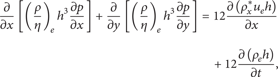
where (ρ/η) e , ρ x *, and ρ e are defined in [9]. For the Ree-Eyring fluid, the equivalent viscosity can be expressed as

2.2.3. Film Thickness Equation
Consider

where h0(t) is the rigid displacement, h g is the geometric gap, ED is the normal elastic deformation [8], and S12 is the function of the surface roughness.
Consider

where if y < l x , f1 = 1 and f2 = 0; if y > l − l x , f1 = 0 and f2 = 1; else f1 = f2 = 0; l is the length of contact line; r y is the equivalent radius in the side-leakage direction. Consider

The regular sinusoidal surface roughness is applied in the work, and the roughness function reads
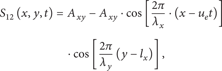
where A xy is the amplitude of the roughness, λ x , λ y are the wave length of the roughness along the x and y direction, respectively, and l x is the modification length at the end of the contact line.
2.2.4. Viscosity and Density Relationships
The viscosity equation and the density equation of the fluid follow the Roelands model [27] and the Dowson-Higginson model [28], respectively:

where A1 = ln η0 + 9.67, A2 = 5.1 × 10⁻⁹ Pa−1, A3 = 1/(T0 − 138), A4 = 138/(T0 − 138), Z = α/A1A2, S = β T /A1A3, α is viscous-pressure coefficient, β T is viscosity-temperature coefficient, and T is the temperature of oil. Consider

where = 0.6 × 10⁻⁹ m2/N, B = 1.7 × 10⁻⁹ m2/N, D = − 0.0007 K−1, T0 is the environment temperature, and ρ0 is the lubricant density on ambient temperature.
2.2.5. Force Balance Equation
Consider

where F is the load and Ω is the calculational domain.
2.2.6. Energy Equation of the Oil Film
Ignoring the heat conduction along x and y direction, the energy equation of the film can be expressed as

where q = (∂/∂t)∫00ρdz′ + (∂/∂x)∫00ρu f dz′ + (∂/∂y)∫00ρv f dz′.
2.2.7. Energy Equations of Solids
The energy equations of the solids read
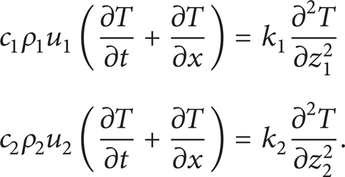
The continuous condition and the boundary condition of the thermal EHL model can be found in [9].
3. Model Simplification and Numerical Method
During the engaging process of the helical gear pair, the load, the length of the contact line, the radius, and the roughness all vary. In existing studies, the micro-TEHL problems are normally treated with a quasi-steady-state way due to the limitation of the calculational cost.
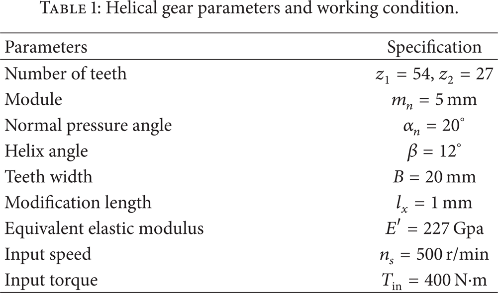
The parameters of the helical gear pair, the fluid, and working conditions are listed in Tables 1 and 2. The numerical solution is obtained by the pressure-temperature iterative scheme, in which the pressure is updated using the multigrid method, and the temperature is updated using the sequential scan technique. The smooth-surface solutions are chosen as the initial values for their rough-surface problems. The dimensionless calculational domain is X = [− 4, 1.5], Y = [0, L]. The dimensionless depth within the solids for the temperature calculation is Z = [0, 3.5]. Five levels are chosen in the multigrid frame, with the highest level being 257 × 513. Within the film, 10 points are set with equal space, while within the solids, and 5 points are set with equal ratio. The convergence criterion is chosen as 10−4 for pressure, 10−3 for load, and 10−5 for temperature.
Helical gear parameters and working condition.
Material properties of the lubricant and solids.

4. Results and Discussions
4.1. A Typical Solution for Micro-EHL of Helical Gears
A regular surface roughness is studied, as shown in Figure 2. The amplitude of the regular roughness is A xy = 0.1 μm, while the wavelengths are λ x = 0.06 mm and λ y = 0.6 mm. Figure 3 shows the contact radius, the rolling speed, and the slide/roll ratio for the helical gear pair.

Surface roughness on the tooth surfaces.
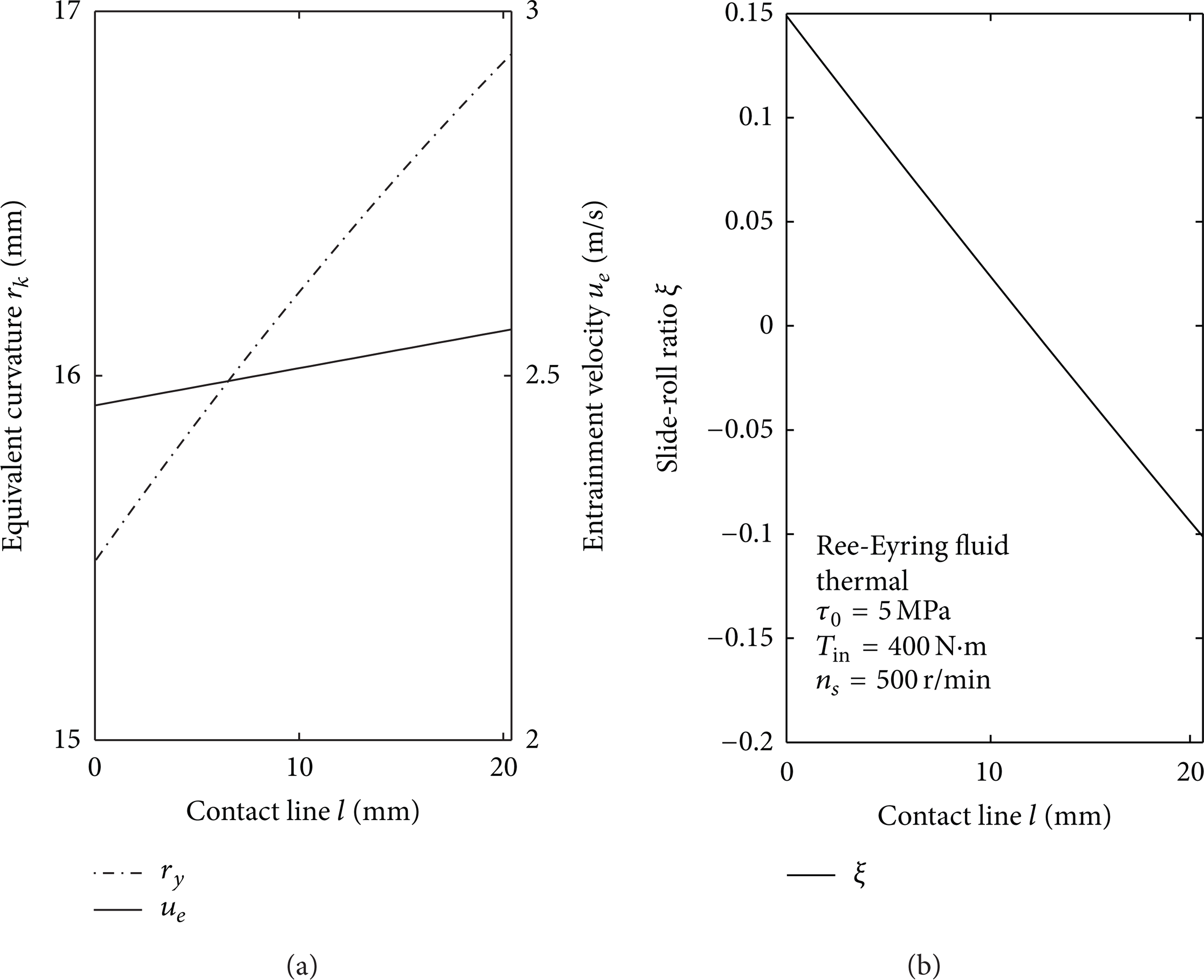
Geometric and kinematic parameters for helical gears.
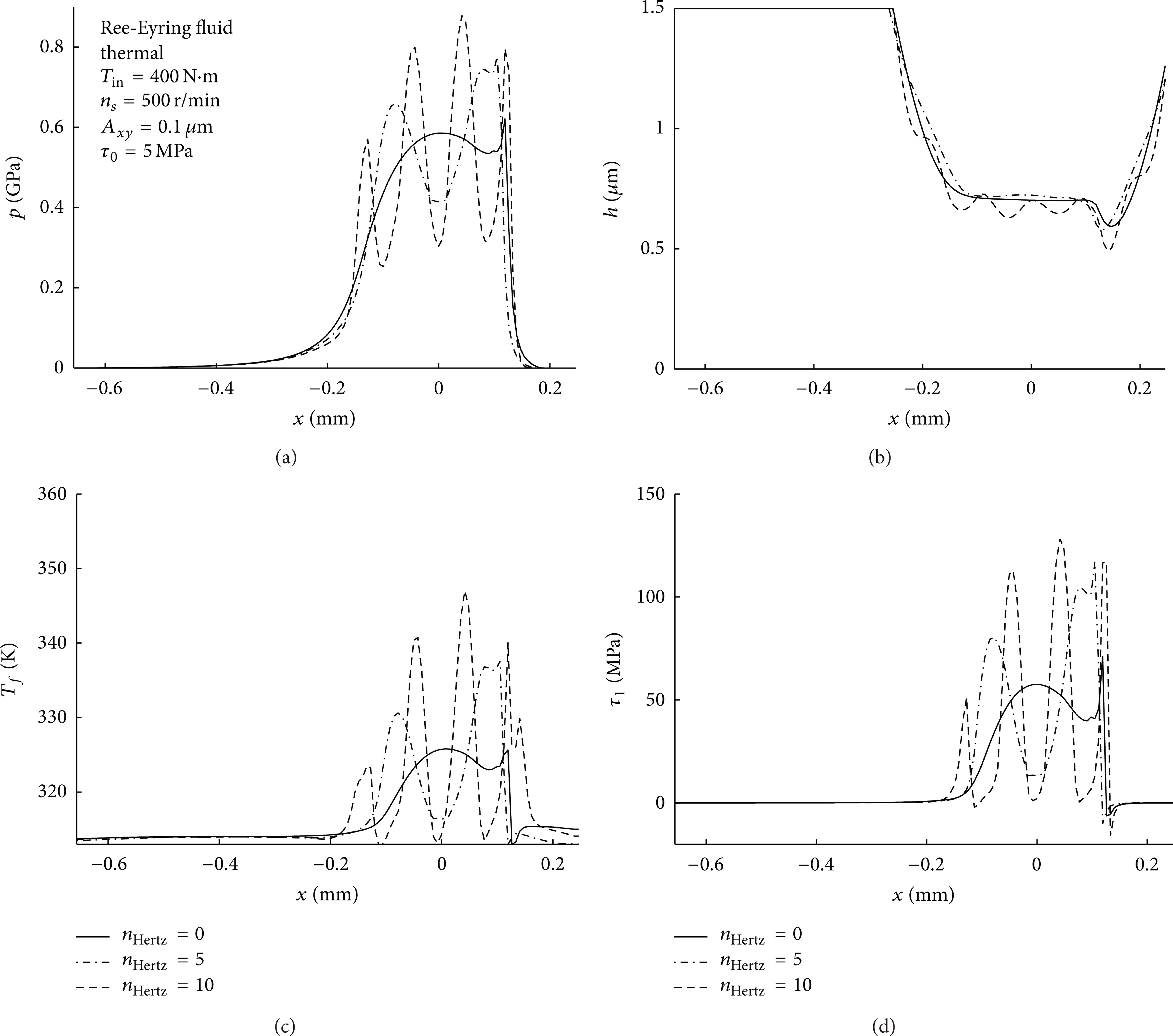
Figure 4 shows the micro-EHL solutions for the chosen case. It can be seen that the surface roughness causes significant fluctuations of the pressure, film thickness, and the temperature. The section x = 0, y = l/2 is chosen to show the comparison between the rough-surface solutions and the smooth-surface solutions, as shown in Figure 5.

A typical solution for micro-EHL of helical gears.

Comparison of rough-surface solutions and smooth-surface solutions.
It can be seen from Figure 5 that the pressure of the rough-surface results fluctuates around the smooth-surface solution. The pressure may rise up to 50% of the original smooth-surface solution. The temperature distribution is similar with the pressure shape. The local rising of the pressure and the temperature might cause surface failures such as micropitting or scuffing. Figure 6 shows that the roughness has been compressed about 50% in the nominal Hertzian contact region. The conclusion is consistent with the pressure distribution.
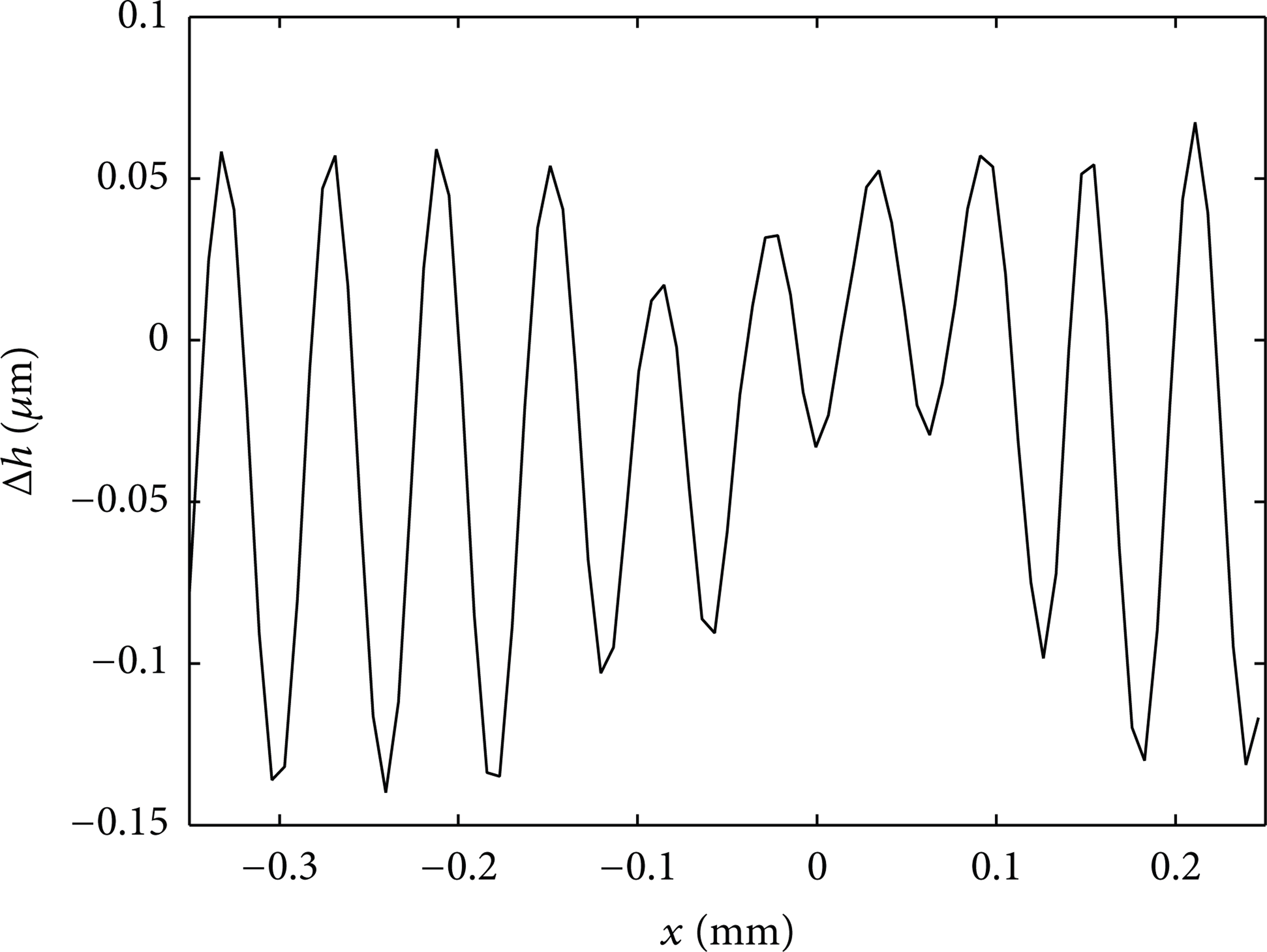
Film thickness difference of smooth and roughness surface.
Figures 7 and 8 show the shear stress distribution and the fluid velocity distribution within the nominal contact zone. It can be seen from Figure 7(a) that, along the contact line, the shear stress would experience a change of direction when passing the pitch point. Figure 8(c) shows the roughness causes the fluctuation of the fluid velocity, especially at the margin of the nominal Hertzian contact zone. Along the rolling speed direction, the surface roughness blocks the flow of the fluid, which makes the fluid velocity at the inlet zone decreasing. With the combination effect of the film contraction and the surface roughness, the film thickness decreases at the outlet zone. In order to follow the mass conservation law, the velocity of the fluid at the outlet zone would increase.

Shear stress distributions along x and y directions.

The velocity of the fluid within the nominal contact zone.
4.2. Effects of Working Condition
4.2.1. Effect of Load
Figure 9 shows the effect of load on the pressure and temperature distribution; as the load increases, the pressure, the temperature, and the shear stress within the nominal contact zone increase while the film thickness decreases. This conclusion corresponds well with the smooth-surface solutions which are shown in [9].

Effect of load on the pressure and temperature distribution.
4.2.2. Effect of Speed
Figure 10 shows the effect of speed on the pressure and temperature distribution. As the speed increases, the film thickness and the film temperature increase, while the pressure distribution does not change significantly. The shear stress within the nominal contact zone decreases. Those conclusions correspond well with the smooth-surface solutions. As shown in Figure 10(b), the speed has no effect on the shape of film thickness.

Effect of speed on the pressure and temperature distribution.
4.3. Effects of Roughness Parameters
4.3.1. Effect of Amplitude
Figure 11 shows the effect of amplitude of the roughness on the temperature, film thickness, and the pressure. As can be seen, as the amplitude increases, the fluctuation of the pressure becomes remarkable, while the maximum local pressure within the nominal contact zone increases. Figure 11(c) shows that the local shear stress increases to over two times of the smooth-surface result. Figure 12 shows the difference of film thickness between smooth and roughness surface with several amplitudes. As the amplitude goes up, the compression ratio of roughness increases in the Hertzian contact region, but this trend is reducing.

The effect of amplitude of micro-EHL for helical gears.
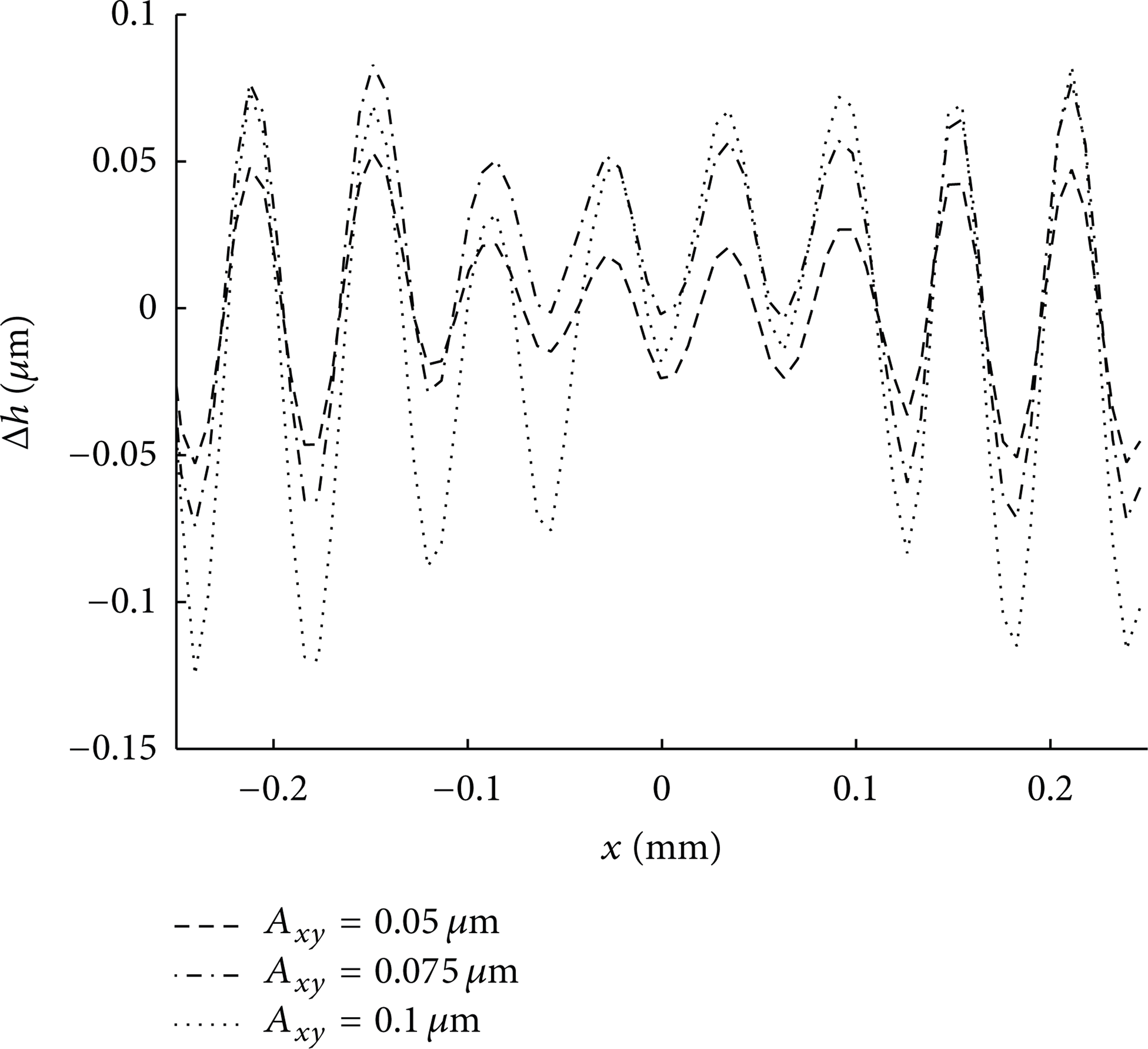
Film thickness difference for smooth and roughness surface with amplitude.
Figure 13 shows the viscosity variation within the nominal contact zone. The variation of the viscosity is caused by the pressure fluctuation and the temperature fluctuation.

The effect of amplitude equivalent viscosity.
4.3.2. Effect of Wavelength
Effects of wavelength are discussed in the direction of the Hertzian contact width (the x direction) and in the direction of the contact line (the y direction).
(a) In the x Direction. Figure 14 shows the effect of λ x on the pressure, film thickness, temperature, and the shear stress. As λ x decreases, the film thickness decreases due to the blocking action of the roughness on the flow. At the valleys of the roughness, since the film thickness is large, the shear stress and the temperature rise are small.
Effect of λ x on the pressure, film thickness, temperature, and shear stress (λ y = 0.6 mm; A xy = 0.1 μm).
(b) Effect of λ y . Figure 15 shows the effect of λ y on the pressure, film thickness, temperature, and the shear stress. Several values of λ y are chosen as λ y = 1.8, 0.9, 0.6 mm to compare with the smooth-surface solution. As λ y decreases, the values of those indexes within the nominal contact zone fluctuate more remarkably. Figure 16 shows the variation of the equivalent viscosity as λ y changes. As λ y decreases, the viscosity fluctuates more remarkably, especially around the pitch point.

Effect of λ y on the pressure, film thickness, temperature, and shear stress.

Effect of λ y on the equivalent viscosity.
5. Conclusions
A micro-TEHL finite line contact model for a helical gear pair is developed by considering sinusoidal waviness on tooth surfaces. Effects of working conditions and roughness parameters are studied. Conclusions can be made as follows.
Surface roughness has a significant influence on the pressure, the temperature, and so forth. The pressure within the nominal contact zone for a rough-surface case fluctuates around the smooth-surface solution. For the working conditions studied, at local area within the contact zone, the maximum pressure may be 50% higher than the smooth-surface result. The film contraction at the outlet zone becomes more remarkable. The film temperature also fluctuates regularly.
As the load increases, the pressure increases while the film thickness decreases within the nominal contact zone. As the speed decreases, the film thickness increases while the pressure does not change significantly. Those conclusions correspond well with the smooth-surface results.
As the amplitude of the roughness increases, the local pressure within the nominal contact zone increases while the minimum film thickness decreases. As the wavelength of the roughness decreases, the local pressure and the temperature within the nominal contact zone increase while the film thickness decreases. Effect of wavelength on the lubrication performance is more evident along the rolling speed direction than along the contact line direction.
Footnotes
Nomenclature
Conflict of Interests
The authors declare that there is no conflict of interests regarding the publication of this paper.
Acknowledgments
This project is supported by National Natural Science Foundation of China (Grant nos. 51405142 and 51405042) and High-Level Personnel Fund of Hubei University of Technology.