
Abstract
Wireless multimedia sensor networks (WMSNs) are more and more wildly used for a variety of applications nowadays. The quality-of-service (QoS), as a measure of system performance, is very important and attracts many researchers. The limited bandwidth should be adjusted for the packets with different priorities precisely. Even more, when the WMSNs are used for environment monitoring, besides the real-time video playing, the monitoring systems also need to record and playback the video after some time. So the necessary and proper retransmission should be added to the real-time video transmission, without affecting the normal data streams. To emphasize the problem, the paper provides a flexible and reliable traffic control protocol. According to the packet priorities, sensor nodes in one collision area can adjust their sending states adaptively. Variable retransmission tactics are provided for the packets with different priorities. The simulations show that the bandwidth adjustment can protect the packets with high priority effectively, and the performance of the retransmission is well positioned to meet the requirement of the multimedia applications.
1. Introduction
Wireless multimedia sensor networks (WMSNs) are generally composed of wirelessly interconnected sensor nodes that can support the multimedia data gathering and transmission [1]. They evolved from the traditional wireless sensor networks (WSNs) gradually used in many different scenes and have very broad application prospects, including security surveillance, traffic and environmental monitoring, wild animal tracking, search and rescue, disaster management, and patient monitoring.
Multimedia traffic, like the video, image, and audio, requires high amounts of bandwidth by its nature characteristics. But in a wireless collision domain, only one node can send its packet at a time, and the wireless links in the network are not reliable. So the wireless transmission for multimedia with the guaranteed QoS in WMSNs is of prime importance due to higher data-rate requirements on the limited and variable capacity of channels. However, for the same reason, the related control mechanism should be simplified to reduce the occupation of the bandwidth, and the computation of the algorithm on the nodes also cannot be complex for the limited resource of WMSN node. This is undoubtedly a great challenge for the QoS design in WMSNs.
For different applications, the required QoS is generally not the same. This paper focuses on the video monitoring. First of all, the real time is an obvious requirement for the network. Thus, the time required for coding, transmission, and decoding needs to be minimized. Second, one monitoring system usually contains several camera nodes which have the same importance. Therefore, the network resource distribution to each node should be fair. Third, the video monitoring data may need to playback later on. So the data packets should not be simply discarded when the transmissions are failed. Some necessary retransmissions are needed to guarantee the fluency and the continuity of the video.
In this paper, we propose a flexible and reliable traffic control protocol (FRTC) for wireless multimedia sensor networks. We divide three priorities for different packets and create a finite state machine for the nodes. During network operation, in order to protect the high priority packets, the state of each node can be adaptively adjusted to trace the transmission of different packets accurately. This tactic can be applied to any node in the network.
The main contributions of this paper are summarized as follows. (1) We build a finite state machine and propose an adaptive and flexible bandwidth assignment mechanism for the video transmission in the wireless multimedia sensor networks. Each node can adjust its bandwidth according to the current state. (2) We propose the different retransmission mechanisms for different packets. The packets with lower priority can be stored temporarily and retransmitted at a proper time. (3) We provide a protocol for these mechanisms, which is simple and easy to implement.
The rest of the paper is organized as follows. Section 2 provides an overview of the related work. In Section 3, we give the system model and formulate the problem. In Section 4, the algorithms and the protocol are presented. Section 5 presents the simulations and results, and Section 6 concludes the paper.
2. Related Works
The multimedia transmissions are always achieved with the reliable transmission medium nowadays, which can support the proper QoS requirement for variable scenes. Generally, the QoS requirements of the video monitoring contain three aspects: bandwidth, reliability, and latency. The more bandwidth a node can use, the higher reliability can be achieved and the less time delay is. In the WMSNs, due to the unreliable wireless link and the huge amount of data, the bandwidth assignment of the wireless links needs to be considered carefully. The traditional QoS methods [2, 3] for WSNs are generally unsuitable for WMSNs. An efficient traffic control scheme is required for the QoS under wireless connections.
The bandwidth adaptive assignment is the main problem for the traffic control. In [4], priority is assigned to each packet according to its importance to the video. Then, the optimal bandwidth allocation strategy is used for limiting the loss percentage of the high priority packets. Reference [5] prioritizes certain (but not all) video packets and ensures that more resources were allocated to these packets than to the others. It also ensures that such preferential treatment to one class of traffic does not rob other low priority traffic of their fair share of resources. QCCP-PS [6] uses the queue length as the indication of the degree of congestion. The bandwidth assignment to each node is based on the priority of the data packets and the current congestion degree. AMPH [7] provides high channel utilization with a hybrid and adaptive behavior. It integrates a new efficient prioritization scheme to provide QoS support and fair data delivery of heterogeneous traffic. ECODA [8] uses a flexible queue scheduler. The packets are scheduled according to their priority for congestion avoidance. It differentiates locally generated traffic and route-through traffic for the queue control. The main ideas of these researches are to classify the priority of the packets and guarantee the transmission of these packets by the resource assignment. But they do not consider the packets with low priority, which sometimes may be lost with no protecting mechanism.
For the usage of monitoring, the request of the real time and reliability is very strict. EAQoS [9] consistently performs well with respect to real-time and energy metrics, which considers the delay and jitter together in the network. C-DMRC [10] is designed with the objectives to maximize the received video quality at the receiver and to prevent network congestion while maintaining fairness between multiple video transmissions. To balance energy consumption and reliability, ERTP [11] dynamically controls the maximum number of retransmissions at each sensor node. It also considers the retransmission time of each hop. The main drawback of this protocol is that it does not use any priority scheme and does not provide adaptive bandwidth sharing for different links.
The traditional TCP protocol for retransmission has time delay and increases data traffic in the network. If UDP is used only, the quality of the service would not be good when there are many nodes in the network. The retransmission in the multimedia transmission is usually not used for time delay consideration. In the WMSNs, the unreliable link quality requires some necessary retransmission. Reference [12] adopts RTP-on-TCP transmission mode to improve the quality of service on wireless network. Reference [13] proposes NACK-based repair mechanism coupled with an adaptive MAC layer retransmission scheme in order to reduce real-time end-to-end delay while maintaining reliability and energy efficiency in the presence of high channel error rates. Reference [14] proposes an aware-based adaptive opportunistic retransmission control scheme for WMSNs. The maximum number of retransmissions is adjusted adaptively.
3. The System Model and Problem Formulation
3.1. The Formation and Transmission of the Video Data
Our protocol adopts the H.264 standard for the video coding. For the video monitoring, real time is essential for video transmission. As the coding and decoding of the bidirectional interpolated prediction frames (B Frame) need to wait for the next frames, we only use inter frames (I Frames) and predicted frames (P Frames). The data needs to be compressed as much as possible to meet the limited bandwidth of the wireless multimedia sensor networks. However, occasionality is another notable characteristic of the video transmission. Different kind of frames has different and random amount of data. The data of I Frame is always much larger. However for P Frame, the amount of data can be large or small depending on the motion of the objects.
The data packet construction should consider the reliability and the real time for the packet transmission. The length of a packet should meet the requirement of the transmission in the WMSNs. If one packet only contains few data, the node needs to transmit frequently. This would not only waste energy, but also cause more collisions by the competitions in the wireless channel and increase the probability of the congestion. However, if one packet has large amount of data which may contain several frames, each packet needs to wait for all of the video frames generated, which causes more time delay. Furthermore, as one packet is successfully transmitted only if each bit in the packet is correctly received, the successful transmission rate is low if the length of a packet is large.
So the maximum packet length is appointed as
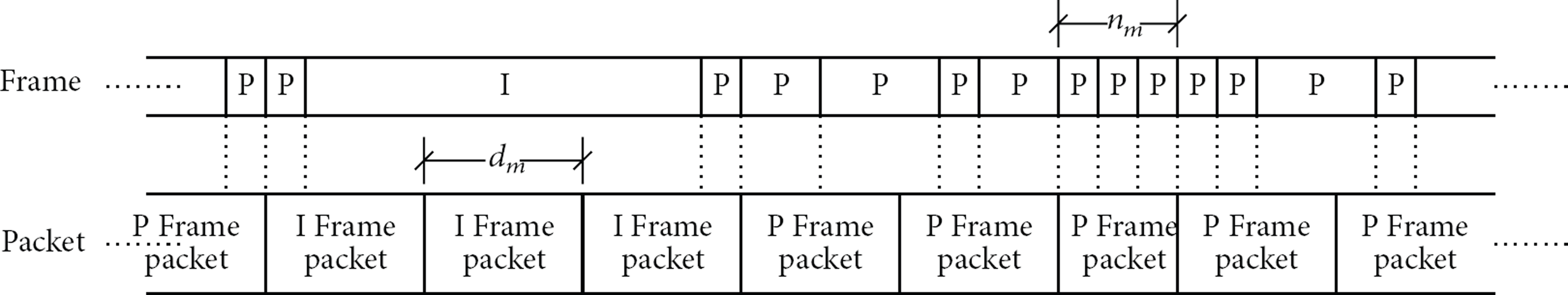
The packet construction with different frame length.
As the wireless transmission is unreliable, the packet lost in the wireless network is an unavoidable characteristic. If an I Frame packet is lost in transmission, all of the P Frames after it cannot be decoded correctly and will be useless. On the other hand, if some P Frame packets are lost, the video decoding can still be going on, only with some mistakes in the video. Usually, the interval of the I Frame is at least 1 second and sometimes may be set much larger for decreasing the total data amount. If the retransmission of the lost I Frame packets is fast enough, the effect of the lost packets may not be notable. So the I Frame packets must have higher priority than the P Frame packets, and the quick retransmission of the lost I Frame packets is essential.
3.2. The System Construction
The model of wireless multimedia sensor network is assumed to consist of one sink node and several identical static sensor nodes which send their packets to the sink node over multihops. The route of the network is a tree and each node sends its data packets to its parent. Each node has a certain storage capacity. The IEEE 802.11g is adopted as the MAC protocol, which uses carrier sense multiple access with collision avoidance (CSMA/CA) algorithm to avoid the collision. For this algorithm, the more data packets in a collision area need to be transmitted at a unit time, the worse the performance is.
Figure 2 shows the role of the nodes in the packet transmission. The node at the center of the circle is the sending node, and the nodes in the circle are in the collision area. When the sending node sends a packet to the receiving node, the interfering nodes in the same collision area must be quite and wait for the sending over. To the CSMA/CA protocol, if the nodes work at the high data rate, the collision can happen frequently, and the performance of the transmission is poor. Therefore, when some nodes are sending packet with higher priority, the interfering nodes need to decrease their data rate in order to protect the higher priority packet. When the high priority packets are sent over, the normal sending rate is resumed.
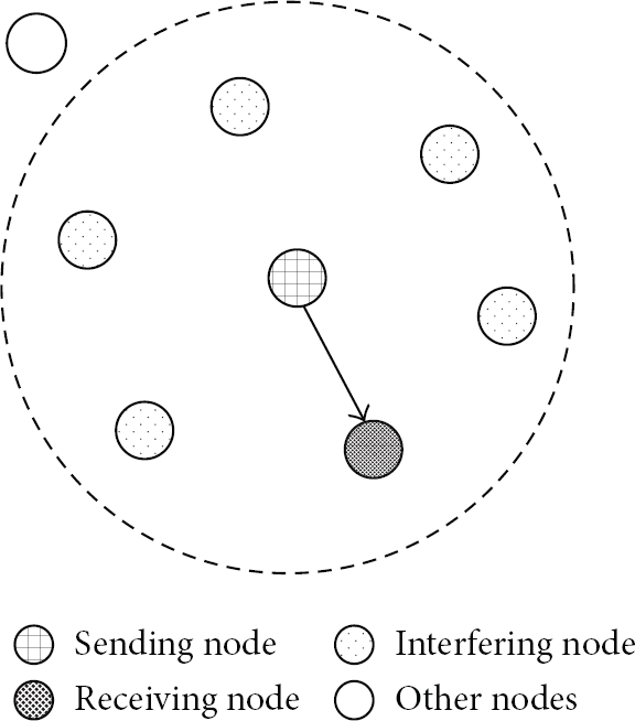
The role of the nodes in the packet transmission.
For bandwidth limitation and the real time, the QoS control in the WMSNs must be simple. If the protocol like RED [15] which is based on the TCP protocol is used for QoS, each packet needs to be confirmed and every lost packet needs to be retransmitted. This will take much of the bandwidth and cause the time delay to wait for the retransmission of each lost packet. So our protocol is based on the UDP transport protocol, but some necessary confirmation and retransmission are still needed. If some I Frame packets are lost, they need to be retransmitted as quickly as possible. But if some P Frame packets are lost, the retransmission depends on the condition of the traffic.
4. Adaptive Traffic Control
To overcome bandwidth limitation, the bandwidth usage of each node in the network needs to be programmed for better performance. We provide a flexible traffic control protocol in the transport layer of the network to support the quality of the video stream. It uses the method of a finite-state machine to assign the bandwidth adaptively.
4.1. Temporary Packet Storage
As the discussion in Section 3, different kinds of packets have different retransmission requirement. According to the degree of importance and emergency, the packets can be classified into four priorities from high to low: the retransmission I Frame packets, the normal I Frame packets, the normal P Frame packets, and the retransmission P Frame packets. Since the normal I Frame and P Frame packets need to follow the sequence of generation, so we can only use three queues for the temporary storage.
Figure 3 shows the packet temporary storage and transmission process at a sensor node. When a node generates or receives a data packet, no matter the packet is I Frame packet or P Frame packet, it is first placed into the normal queue to wait for being sent. After this packet is sent, it is moved to the I-Frame packet pool or P-Frame packet pool depending on its attribute. These two pools are used to store the unconfirmed packets temporarily, waiting for the retransmission if needed. The I Frame is the most important in supporting the real time playing. So if it is lost, the retransmission of I Frame packets has the highest priority. They should be found in the I-Frame packet pool, put into the Lost I Queue, and retransmitted immediately.

The temporary storage and three queues in one node.
The I and P Frame packets are generated continuously and alternately. If a node finds another I Frame packet in the normal sending queue, which is not continuous with the last group and may be transmitted after several P Frame packets, the old I Frame packets already in the I Frame pool are time out. They will be replaced by the new I Frame packets. It is similar to the P-Frame packet pool and Lost P Queue. The differences between the Lost I Queue and the Lost P Queue are only the priority and the retransmission time. The I-Frame and P-Frame packet pools make use of the memory of the sensor node to store the unidentified packets, without affecting the normal sending and receiving of the sensor nodes. This mechanism separates the packets with different priorities and simplifies the management and seeking of the lost packets.
However, for the hardware limitation, a sensor node may not afford a packet pool which is large enough for all the temporary storage. To void the P-Frame packet pool overflow, it should store the packets which are most likely to fail the transmission, which will be discussed in Section 4.3.
4.2. Node Sending States and the State Machine
A packet can have various priorities. The sending rate of a node needs to be adjusted adaptively to protect the packets with higher priority. A node has three main states: normal, slow, and unlimited.
Normal State. It is for the normal transmission. It needs to support the normal video generation but usually should be lower than the maximum allowed sending capacity of a node. If sometimes the coding rate exceeds the initial maximum sending rate, the video data needs to be placed into the queue temporally and waits for being sent.
Slow State. When a node has higher priority packets to send, the nodes in its collision area should slow down their sending rate of normal packets to give more bandwidth for the higher priority packets. According to the number of nodes which are sending high priority packets, the slow state contains several substates. When a node has already decreased its sending rate, but it finds that another node begins to send the packet with high priority, it needs to decrease its sending rate even more. So this node turns to the slower state. We use β to denote the falling speed of the sending rate at each time when a state turns to its next slower one. Therefore, the sending rate at substate n can be expressed as (1), where the S means the sending rate of the state. Consider
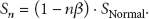
For the fairness, a minimum sending rate must be guaranteed, so that the bandwidth cannot be occupied by a few nodes and others are starving. If a node reaches the minimum sending rate, it cannot decrease its sending rate any more. The normal, minimum sending rate and β can be obtained from the experiments.
Unlimited State. This state is only used for the retransmission of the lost I Frame packets. Because the lost I Frame packets need to be retransmitted as quickly as possible, these packets are not limited by the speed control. But the other nodes need to slow down to give up bandwidth. When a node is at the unlimited state, the other nodes should set their sending rate to the minimum state. After a short period of time, all the nodes can resume their previous sending rates.
The unlimited states and the corresponding minimum slow substate can be called enforcement states. To the opposite, the normal and slow states can be called free state, because these two states can be changed when required. The states can also be divided into different priorities. The unlimited state and the minimum slow substate have the highest priority. The normal state to send the normal I Frame packets has lower priority. The normal state for sending the P Frame packets and the slow substates have the lowest priority. According to the current condition of the network and the neighbor nodes, each node needs to adjust its state at the proper time. The state with high priority can interrupt the lower ones. When a node needs to change its state to a higher one, it needs to save the current state first. When it no longer needs to be at higher state, the node turns its state to the previous saved one. On the other hand, the lower state cannot interrupt the higher state. It must wait for the task of higher state over and then makes the state change. The sending state change can protect the packets with high priority. When the packets with high priority are being sent, other nodes which can be seen as the interrupted nodes would slow down their sending rate, in order to decrease the probability of the collision in the wireless channel, so the packets with high priority would meet less collision and have much more chance to be transmitted successfully.
The transform of these states is shown in Figure 4, which can be concluded as follows.
When a node begins to work in the network, it uses the normal state as the initial state. When a node is at a free state and finds some other nodes in its collision area sending I Frame packets, it will change its state to the next slower one until the minimum slow substate is reached. When a node is at a free state and finds some other nodes to stop sending I Frame packets, it can increase its state to the upper level until the normal state is reached. When a node needs to send the normal I Frame packets, it can save and update its current free state and turn to the normal state to send I Frame packets. When the transmission of I Frame packets is over, it can turn back to the latest free state. No matter what the current state is, if the node has some lost I Frame packets to retransmit, it turns to the unlimited state immediately. When retransmission of these lost I Frame packets is over, it returns to its latest free state. No matter what the current state is, if a node finds some nodes to retransmit the lost I Frame packets, it needs to change its state to the minimum state immediately. When the retransmission of the lost I Frame packets is over, it returns to its latest state. When a node changes it state to a lower one, it starts a timer. If it does not receive the information for the ending of the slow state until the timer is out, it will increase its state to the upper one.

The state machine for each node.
4.3. Adaptive Retransmission of P Frame Packets
The retransmission of the lost P Frame packets has the least priority. If some P Frame packets are lost, with the simple mechanism of retransmission, they may not be useful for the real-time play, but they can be useful for the playback. So the time delay of the lost P Frame packets is unimportant and does not need to be considered. However, we need to consider the impact of the retransmission of the P Frame packet, which should give less effect on the normal transmission. Usually, the main reason of packet lost is heavy traffic. The retransmission of the P Frame packets should be arranged at the time when the link is not busy, in order to avoid collision and not disturb the normal packet transmission. Since the video stream has the characteristic of continuity, when some object is moving in a frame, it will last for some time. So we can predict the data rate of the network by the analysis of the current data rate. Because the instantaneous data sending rate of the wireless channel cannot be measured accurately by the nodes, we use the average sending rate of previous time to represent the current link traffic condition. This value is updated frequently to evaluate the link utilization. It can be denoted by
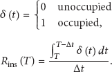
The distribution of the instantaneous sending rate of the network can be shown in Figure 5. We choose θ as the retransmission probability for sending rate being less than ρ. Consider

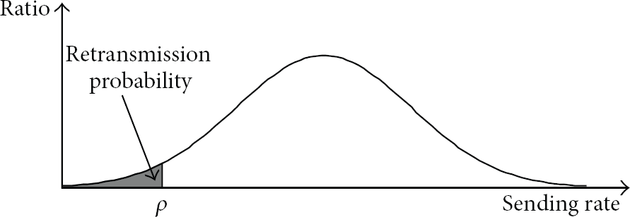
The retransmission probability of the lost P Frame packets.
If

The temporary storage of the P Frame packets may cause another problem. Because the memory space of the sensor nodes is limited, sometimes it may not be enough for the unconfirmed P Frame packets. If the P Frame pool overflows, it is not a good idea either to drop the new ones or to overwrite the oldest ones. It is better to store the packets with the higher probability of loss and drop the packets with higher probability of success. As the nodes always detect the vacancy ratio, this parameter can also be used for choosing the overwritten packets. If a packet is being sent at the time of channel being very busy, the probability of lost packet is much higher than the time of the channel being idle. If some new packets come when the P Frame pool is full, the packet with the highest sending vacancy ratio at the sending time will be overwritten.
4.4. The Traffic Control Protocol
The traffic control is accomplished by the command packets. Since wireless transmission is in broadcast fashion, if one node receives all the data packets from its neighbors in the collision area, it will take a great burden for processing, computing, and storage. Therefore, besides the normal packet transmission, we adopt some command packets only for the network control. The multicast transmissions in our system are only for these command packets. For the bandwidth limitation, the WMSNs cannot afford too much bandwidth and time delay for transmitting the control packets iteratively. Thus, the control needs to be simple.
The traffic control is different for I and P Frame packet transmission. The I Frame packets request higher reliability and less time delay. Therefore, the control mechanism should be in synchronous communication. Each command packet needs to be confirmed in the duration of validity. But to the P Frame packets, we do not adopt the synchronous transmission for the control packets; that is, not all the command packets are expected to be transmitted successfully.
The information contained in a command packet is shown in Table 1. This is a general format for all the command packets which are used in the protocol. Each kind of the command packet needs to fill the correspondent fields for construction.
Fields in the command packets.

For the I Frame packets, as shown in Figure 6, all control packets are checked carefully and sent immediately. This mechanism is like the traditional TCP control, but the difference is the broadcast of the command packets. The step with double-line box in Figure 6 means the packets are broadcasted to all the nodes in the collision area. Before a group of I Frame packets begin to be sent, the node broadcasts a start beacon to the nodes in the collision area. The interference nodes adjust their states according to this command packet.

The process for I Frame packets transmission.
When a parent node receives a start beacon, it knows the next packet contains the data of I Frame. If the parent node receives all the I Frame packets of the I Frame, it returns an ACK to tell its son and the transmission of this I Frame is finished. If not, the parent node returns the sequence number of the lost packets. Then its son begins to retransmit the lost packets. These two kinds of return packets are broadcasted to all the nodes, and they should be guaranteed to be received by its son. For preventing the control packets from being lost, each control packet needs to be confirmed by the parent and son. If the son does not receive any confirmed packet in some time, it needs to send a finish beacon to tell its parent that time is out for waiting for the confirmation. The parent needs to resend the return packets. Once confirmed that the I Frame packets have been received by the parent node successfully, they can be deleted in the pool of the son node.
The control retransmission of the I Frame packets needs to be enforced. However, there is no mechanism to guarantee the broadcast command packets being received by all the nodes in the collision area due to the unreliable bandwidth. The other nodes do not give any feedback to the sender. If some command packets are lost at some nodes, these nodes cannot change their states. Fortunately, this situation does not cause much problem to the transmission.
For the P Frame packets, the network overflow should be considered in the confirmation mechanism. There is only one chance for the parent node to give the confirmation after receiving/sending a group of P Frame packets. The confirmation contains the packet sequence number which is lost but still has chance to be retransmitted. And the lost P Frame packets need to be retransmitted when the network link is available. After the sink node receives the packets out of order, it adjusts the packet order according to the packet sequence number.
For the P Frame packets, as shown in Figure 7, the transmission process is much simpler than that of the I Frame packets. There is no broadcast step in this part of the protocol. Each group of the P Frame packets has only one chance to get confirmation. After the parent node receives a group of P Frame packets, if no P Frame packets need to be retransmitted, the transmission of this group is finished with no ACK packet. Otherwise, if the parent still has some lost P Frame packets, it returns their sequence numbers. If the lost ones can be found in the P-Frame packet pool, these packets will be retransmitted at a proper time. If the parent still cannot receive the requested packets after calling for retransmission for several times, it thinks that the packets are lost at its son and will not recall these packets anymore.

The transmission process for P Frame packets.
5. Simulation and Analysis
In this section, we present the simulation of the FRTC protocol. First, we give out a simulation system model of a typical monitoring application. Based on this model, the simulation and analysis results for different parameters are compared.
The network for simulation contains three kinds of nodes: the source node which has a camera to generate the video data, the relay node which does not have a camera and is only used for the packet forwarding, and the sink node which receives and processes the packets for the video storage and play. The topology of the network for simulation is a simple tree, which is shown in Figure 8. All the nodes work in the same collision area. The video packets can be transmitted from a source node to the sink via the relay nodes by multihop route.

The topology of the network in the simulation.
The main simulation parameters of the source node are shown in Table 2. Our channel model assumes that the node-to-node packet lost ratio follows the Gauss distribution. The average value of the lost ratio increases with the larger data amount transmitting at the same time. We use MATLAB for the simulation. The amount of the video is simulated as the monitoring video using in the rooms; as shown in Table 2, the length of the I Frame is a random value between 7 and 13 Kbytes; and the length of the P frame is also a random value between 12 and 3000 bytes. The relay nodes have double capacity than the source nodes. The sink node is assumed with sufficient hardware to support any request of the network. In our simulation, we change the parameters separately and test for the performance.
Simulation parameters.

5.1. The Retransmission of the Lost P Frame Packets
The retransmission probability is an important parameter in the protocol. Figure 9 shows the simulation result of the retransmission probability for lost P Frame packets, where the size of the P-Frame packet pool is assumed to be unlimited. The x-axis in the figure is the ratio of the retransmission probability.

The effect of different retransmission probability for lost P Frame packets.
If the retransmission probability is very small, the retransmission is only allowed when the network instantaneous traffic is very low. There is not enough chance for retransmitting the lost P Frame packets. Therefore, the final lost ratio of the P Frame packets is high. With the increase of the retransmission probability, the more lost P Frame packets can be sent and received. However, if there are too many retransmissions, this will lead to retransmission of the lost P Frame packets at the time when the network traffic is relatively crowded. Therefore, an appropriate retransmission probability should be carefully chosen to meet the requirement of retransmission. Thus, the impact of the retransmission to the normal network traffic can be minimized.
The objective of setting the packet pool at a sensor node is to store the lost packets temporarily for retransmission. The size of the packet pool does not affect the first time packet transmission. As the I Frame packet length does not change much, the retransmission can be predicted accurately. The size of I-Frame packet pool can be determined easily. However, the P Frame packet length varies and is difficult to be predicted. The size of the P-Frame packet pool should be as large as possible. Figure 10 shows the relationship between different size of the P Frame pool and the retransmission successful ratio of the lost P Frame packets. As the I Frame interval is 50 frames, the P-Frame packet pool needs to receive the data for nearly 2 seconds. As network parameters are fixed except the data rate, the greater the average data rate is, the greater the size of the P-Frame packet pool is. The y-axis is the retransmission successful rate. If the size of the P-Frame packet pool is not big enough, some lost packets cannot be placed into the pool before retransmission. Therefore, for a fixed size of the P-Frame packet pool, the greater average data rate leads to the lower storage of the lost P Frame packets. Thus, the retransmission successful ratio is also lower.
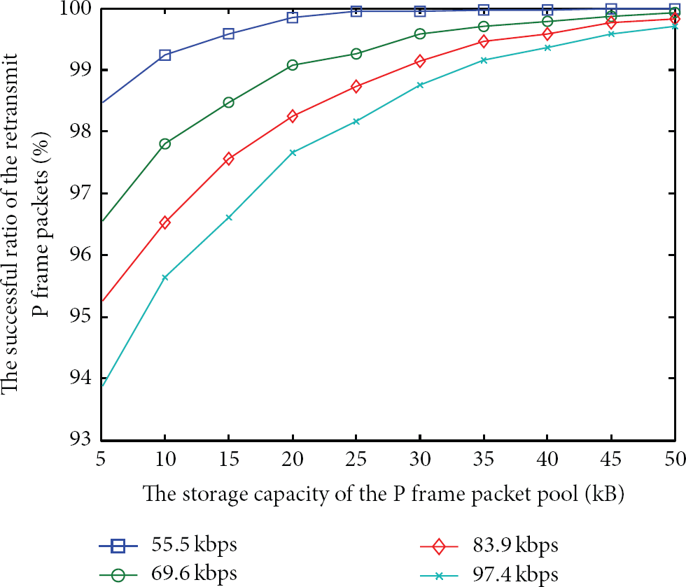
The effect of the size of the P Frame pool at the source node.
5.2. State Change
The objective of our protocol is to protect the packets with high priority. The decrease of sending rate for each slow substate plays an important role in the performance. In Figure 11, we can see that for each substate, when the sending rate declines faster, the packet lost rate of the I Frame at the first time transmission is lower.

The effect of the ratio of slowdown for each slow substate.
As the increase in the sending rate declines for each slow substate, the lost ratio of the P Frame packets at the first time transmission first decreases and then increases. When the I Frame packets are generated and transmitted, the data amount is large at the moment, which makes the wireless channel to be busy. If the number of P Frame packets to be sent at this time is reduced, the transmission successful ratio will increase. But if the interference nodes decrease their data sending rate too much, there will be more chances to transmit P Frame packets at the other time. Therefore, the lost rate of the P Frame packets will rise.
5.3. Packet Lost Ratio and Time Delay
By adjusting the average data rate at the source nodes, we can compare the lost rates of different kind packets. The lost I Frame packets are retransmitted until they can be received successfully; that is, no matter what is the lost rate of the I Frame packets at the first time transmission, the final lost rate is always 0. For the P Frame packets, the performance decreases with the increase in the average data traffic. From Figure 12, we can see that our protocol has a certain effect to protect the I Frame packets, as well as the retransmitted P Frame packets.

The packet lost rate for I and P Frame packets.
We compare the quality of the video with our previous work FATS [16]. We use the lost effective factor (LEF) to show the effect of the packets lost on the video quality. If the I Frame packet is lost, there would be an error in the video in the time of this period and it cannot be played. This can be seen as the failed time. However, if the P Frame packet is lost, the video in the next time of this period still can be played, but it would be affected. So we can statistic the failed and affected time during the video transmission, just as a criterion to judge the quality of the received video. The result is shown in Figure 13.
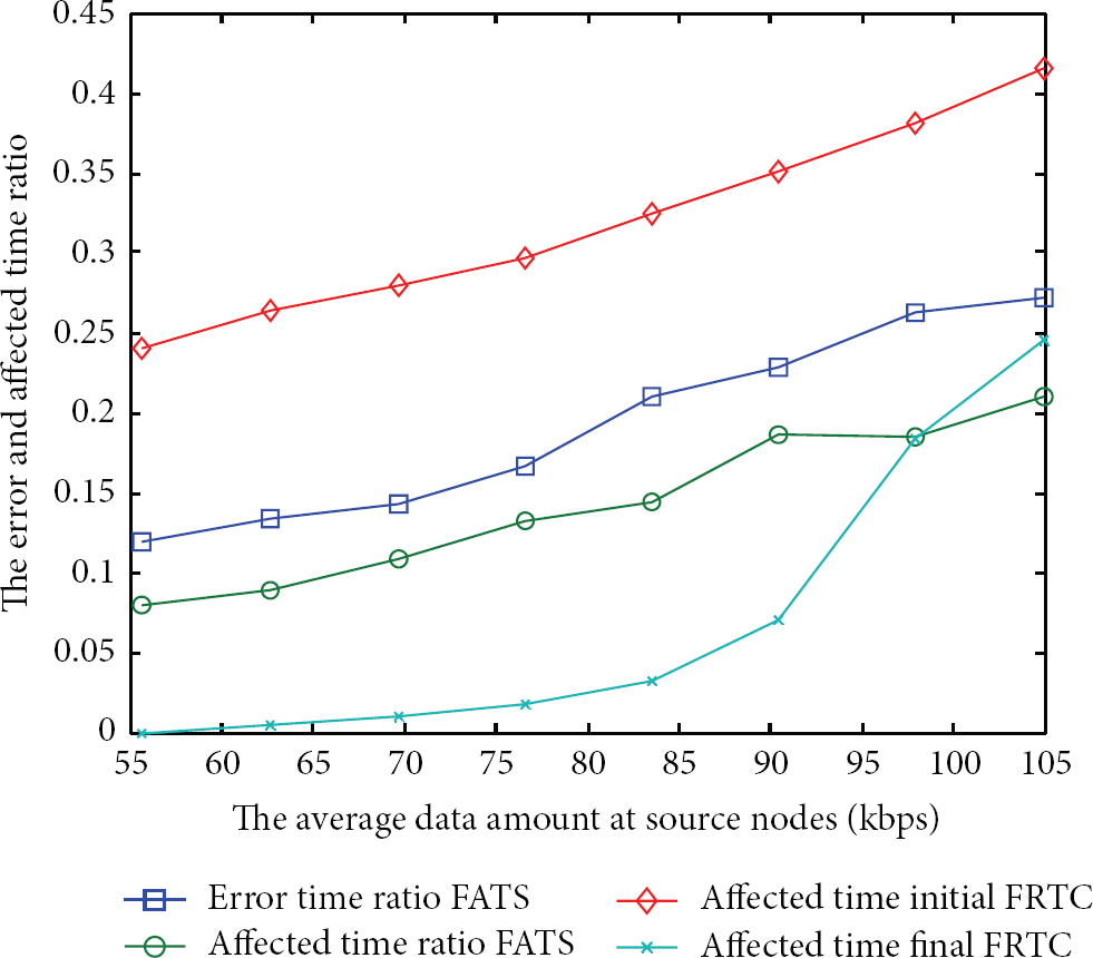
The failed and affected time ratio of the FRTC and FATS protocols.
In Figure 13, because our protocol has more mechanisms to protect the I Frame packets, for the video real-time playing, there are no I Frame packets lost, and the initial and final error time of the FRTC are all zeros for all the data amount. So we do not show them in this figure. But these mechanisms sacrifice the transmission chance of the P Frame packets, so the initial affected time of the FRTC is larger than that of the FATS. However, no I Frame packets lost means the video would not be interrupted, so the performance of the initial video quality of the FRTC is better than the FATS.
For the video replay, with the adaptive retransmission of the P Frame packets, many lost P Frame packets can be retransmitted and fill in the blank of the video. So the final affected time of the FRTC is much less than the FATS. Overall, the mechanisms of the FRTC are quite effective to increase the video quality.
The time delay is defined as the time from the frame generation to reception by the sink. It contains the time for packet generation, the time for waiting in the queue at both the source node and the relay node. We classify the packets into different categories, as shown in Figure 14. Because the retransmission of the lost I Frame packets always happens at the time when normal I Frame packet transmission is finished, the average data rate has a little impact on the I Frame packet transmission.
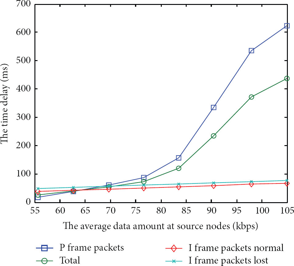
The time delay for different data rates.
When the data rate is low, most of the data comes from the I Frame. The transmission of the I Frame packets happens in a short period of time. In another time, there are few packets to send. So the queue of the node is almost empty and the time delay is very small. With the increase in average data rate, the workload for P Frame packet generation and transmission increases. The competition for the wireless channel increases as well. So the queue becomes longer and the time delay also increases.
6. Conclusion
In this paper, we have proposed the FRTC protocol for flexible and reliable traffic control in wireless multimedia sensor networks, which are used for video monitoring. FRTC classifies the packets into four priorities and builds a finite-state machine to protect the packets with high priority. The simulations show that the FRTC has good performance in terms of the packet protection and retransmission. The important video frames can get more bandwidth during the transmission and retransmission. In addition, the retransmission of the lost P Frame packets has little effect on the normal transmission, but the performance of the video playback can be significantly better than the real-time playing.
Footnotes
Conflict of Interests
The authors declare that there is no conflict of interests regarding the publication of this paper.
Acknowledgment
This work was partially supported by the funds of Shenzhen government under Grant nos. JC201005270349A, JC201104220264A, NST2011-002, CXB201104220033A, CXY201107010216A, and CXZZ20120831173053551.