
Abstract
The effect of film cooling parameters on the cooling effectiveness of an actual turbine blade is studied numerically. Film cooling parameters such as the hole shape, holes distribution, blowing ratio, streamwise angle, and spanwise angle are investigated to select the appropriate cooling parameters. Unstructured finite volume technique is used to solve the steady, three-dimensional, and compressible Navier-Stokes equations. Using one cooling holes array indicates that the average overall film cooling effectiveness is enhanced by decreasing the streamwise angle for high blowing ratio on the suction side of the turbine blade. The film cooling effectiveness is enhanced on the pressure side for a blowing ratio of unity. In addition, the cooling effectiveness increases by increasing the lateral and forward diffusion angles. The computations reveal that the efficiency of cooling is decreased at the leading edge due to the large surface curvature of the blade. The presence of compound shape (spanwise angle) enhanced the film cooling effectiveness on the two sides. Multistagger cooling hole arrays are investigated and the results indicate that five-stagger cooling arrays on the pressure side and three-stagger cooling arrays on the suction side with LFDCA-9.3-14.6 hole shape are enough to have good cooling of the two sides using 2.17% bleed air of the engine.
Introduction
Over the past fifty years, aircraft and power generation gas-turbine designers have focused on increasing the temperature at the combustor exit to improve the engine performance, to increase the thrust, and to reduce the fuel consumption. Unfortunately, high temperatures have a negative effect on the integrity of the high-pressure turbine components, specifically the turbine blades. Therefore, there is a need to have an efficient cooling system engineered in a way such that the maximum blade surface temperature during the engine operation does not exceed the maximum allowable temperature of the blade material.
To achieve this goal, several researchers such as Narzary et al. [1] and Yuen and Martinez-Botas [2] focused on various innovative cooling techniques. Depending on the nature of the coolant flow, the cooling methods currently implemented in the turbine industry can be classified into two main categories which are the internal and external cooling. In the first type cooler air is bled from the compressor stage and then passed through internal passages incorporated into blade designs for this purpose. This is the most common technique and is called enhanced passage cooling. For maximum heat absorption, the air is also allowed to impinge on the internal wall of the blade. This technique is called impingement cooling. In external cooling, air is bled from the compressor stage, ducted through the internal chambers of the turbine blades, and then discharged through small holes/slots on the blade outer walls. This air provides a thin, cooler, and insulating film along the external surface of the turbine blade, due to which the method is called “film cooling.” This film provides blade protection and thus increases the life of the blade.
Film cooling has been found to be very sensitive to many parameters such as the coolant-mainstream density, momentum and mass flux ratios, the mainstream turbulence intensity, mainstream passage/tip vortices, upstream wakes, surface curvature, and roughness. Thorough reviews of the parameters affecting film cooling are provided by Nasir et al. [3], Bogard and Thole [4], and Bunker [5].
The effect of coolant-mainstream blowing ratio is investigated by Rallabandi et al. [6]. The study by Rallabandi et al. [6] indicates that the nondimensional temperature and the film cooling effectiveness increase at low blowing ratios regardless of hole shape and injection angle. However, beyond a critical blowing ratio, film cooling effectiveness decreases. This result can be attributed to the phenomenon of film cooling lift-off, where the high momentum jet fails to attach to the plate surface and the jet penetrates into the mainstream.
The coolant-mainstream density ratio (DR) in modern gas-turbine engines is typically around 2.0, due to the significantly lower temperature of the coolant. Scaled-down laboratory tests, to simulate engines of different density ratio conditions, usually involve chilling the coolant to very low temperatures. In general, increasing density ratio at a given main stream M results in a higher effectiveness, especially at higher blowing ratios, since the velocity of a high density coolant is lower at a given M. Injecting the film coolant at an angle to the mainstream (a compound angle) results in higher film cooling effectiveness, due to a lower tendency to lift-off. Embedding film cooling holes in slots as indicated by Bunker [7] and Waye and Bogard [8] has been found to increase film cooling effectiveness in the proximity of the hole.
Multiple rows of film cooling holes are conventionally used in turbine blade designs. Typical distributions with both simple and compound angles have been studied by Ligrani et al. [9]. At lower blowing ratios, the effects of numbers array are fairly insignificant. However, the double jet row shows higher effectiveness for high blowing ratios. More recently, Kusterer et al. [10] have studied two rows of film cooling holes with opposite orientation and internal supply geometries.
The results of Ito et al. [11] and Schwarz et al. [12] indicate that film cooling effectiveness is relatively subdued on the concave (pressure side) in comparison with the convex (suction side), with the flat plate effectiveness values lying in between. Lift-off occurs at a lower blowing ratio on the concave side. However, the curvature of the concave surface results in a reattachment of the lifted-off coolant on the pressure side, resulting in higher downstream effectiveness. The effect of coolant-to-mainstream density ratio on a vane with high curvature has been studied by Ethridge et al. [13]. Dittmar et al. [14] studied different film cooling hole configurations on the suction (convex) side and concluded that shaped holes provide better coverage at higher blowing ratios by resisting jet penetration into the mainstream. Chen et al. [15] noticed an improvement in performance on the concave (pressure) surface due to using compound angled holes instead of simple angled holes at higher blowing ratios. An improvement is noticed on the suction side at all blowing ratios. Mayle et al. [16] studied slot jet film cooling along flat, convex, and concave surfaces. Compared to the results of the flat surface, convex curvature is found to increase the adiabatic wall effectiveness whereas concave curvature is found to be detrimental. Jiang and Han [17] studied the effect of film hole row location on local film cooling effectiveness on a turbine blade model; results indicated that injection from a different film hole row location provides a different effectiveness distribution on pressure and suction surfaces depending on local mainstream velocity and blade curvature. Berhe and Patankar [18] conducted a numerical study to investigate the effect of surface curvature on cooling effectiveness. For the low blowing ratios considered, the convex surface resulted in a higher cooling effectiveness than both the flat and concave surfaces. For the convex case, the coolant jet is pressed to the surface by a strong cross-stream pressure gradient. On the concave surface, the mixing between the coolant jet and the mainstream is strong, so the cooling effectiveness declines. In addition, Elsayed et al. [19] used the numerical simulation of the coolant flow through flat plate hole system coupled with the optimization algorithm “simplex” to maximize average overall film cooling effectiveness. An optimum lateral and forward hole shape of (LFDSA-9.3-14.6) is obtained.
In the current study, the optimal holes shape which is obtained by Elsayed et al. [19] for the film cooling effectiveness on a flat plate using simplex algorithm is used in the current study as an initial geometry for the hole shapes (CYCA and LFDCA-5-5) on the actual turbine blade GE-E 3 . A parametric study is performed in order to investigate the effect of different hole shapes in terms of lateral and forward diffusion angles, holes position, blowing ratio, streamwise angle, and spanwise angle on the blade cooling effectiveness. The numerical simulation of the coolant flow through turbine blade hole system is carried out using the “CFDRC package.” The solver of this package uses the three-dimensional steady compressible viscous flow field coupled with the k-ε turbulence model. An unstructured grid is used for the simulations. The governing equations are discretized using the finite volume technique with second order accuracy in space.
Numerical Model
Turbine Blade Numerical Simulations.
The present calculations are performed for a GE-E 3 blade. Figure 1 shows the geometry of the GE-E 3 blade with a single suction side squealer tip in order to minimize the tip leakage flow. The blade has a constant chord length of 8.61 cm and an aspect ratio (span to the chord) of 1.4 with a blade tip radius of 35.56 cm. The tip clearance studied here is 1.5% of the blade height and the depth of the squealer cavity is D = 2.1% of the blade height.

Turbine computational domain with single squealer tip shape.
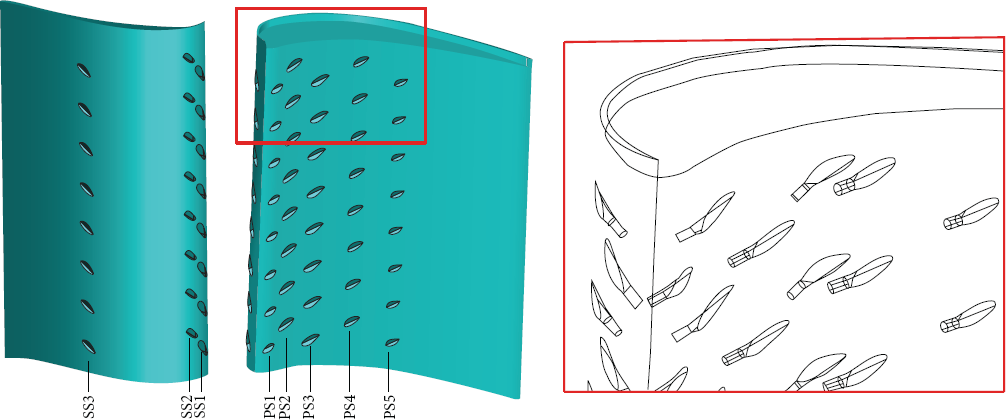
The film cooling used in this study for the GE-E 3 blade has two cooling hole arrays. The first array has eight LFDCA holes and it is located on the blade pressure side at a distance measured from the leading edge to total side length ratio (L/LPS). The second array is located on the blade suction side at a distance measured from the leading edge to total side length ratio (L/LSS), as shown in Figure 2.
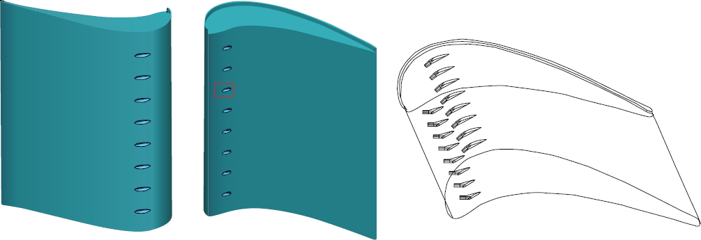
Turbine blades PS and SS with cooling holes.
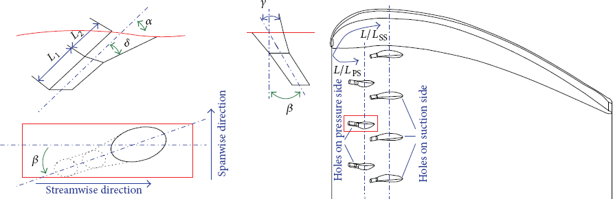
The selected geometry of the cooling hole is taken as the generalized laterally and forward-diffused (LFDCA) (also called fan-shaped laidback) type. The hole configuration is nominated LFDCA-LL-FF, where LL and FF are the lateral and forward diffusion angles. The inlet cooling hole diameter is selected to be 1.27 mm. The variables which define the hole shape are the streamwise angle (α), the lateral diffusion angle (γL), the forward diffusion angle (δ), the spanwise angle (β), and the holes position with respect to the blade leading edge (L/LPS and L/LSS) as shown in Figure 3.
Three views of LFDCA hole shape.
The CFD-Geom of CFDRC software is used to generate a tetrahedral-hybrid unstructured grid for one turbine blade. A grid function is used to adjust the grid size near wall and tip regions as shown in Figure 4. A minimum cell size of 0.2 mm is used at the high curvature area around the cooling hole with a growth rate of 1.1. A maximum cell size of 2 mm is used at the low curvature area (straight area). The growth rate factor is used to adjust the grid number between the two areas. The total number of cells used for the numerical simulations is 1.5 million cells.

Computational model grid for single squealer tip with PS and SS holes systems.
The computational domain consists of a single blade with periodic conditions imposed along the boundaries in the circumferential (theta) direction. The diameter of the inlet film cooling hole system is 0.127 cm and the flow injected with a temperature of 923 K and density ratio ρ/ρ h = 1.2. The inlet boundary is placed at one-half chord length upstream of the blade so that the simple uniform inflow boundary conditions can be employed. A total temperature of 1700 K and a total pressure of 1.675 MPa are specified with an inflow angle of 32°. The inlet flow velocity is 183m/sec. The exit boundary is located at one chord length downstream of the blade trailing edge to provide appropriate resolution of the tip leakage flow and passage vortices. The static pressure is specified as 1.03 MPa at the exit. Therefore, the inlet total pressure to the outlet static pressure ratio (PR = Pin,t/Pout) is 1.63. On the blade surface, the no-slip condition is specified. A rotating speed of 9,600 rpm is used in the present simulation while the shroud remains stationary, as shown in Figure 5.

Turbine blade computational domain and boundary conditions.
Grid Sensitivity Analysis and Verification of the Numerical Model.
In our previous work [19], a grid sensitivity study is performed for a case study having LFDSA-5-5 hole shape with streamwise angle of 30°. The results indicate that the average film cooling effectiveness can be accurately computed for a grid size greater than 400000 cells. In addition, the nondimensional quantity (y+) which expresses the density of grid is controlled for accurate simulations. The results indicate that for accurate resolution of this flow field, the maximum value of y+ should not exceed the value of 5 for this grid.
The film cooling on a flat plate with an injection hole of shape LFDSA-00-00 (CYSA) is simulated numerically and the results are compared with Daud et al. [20]. The simulations of this CYSA hole shape are calculated on unstructured grid and RNG turbulent model. The same boundary conditions of Daud et al. are used in the current simulations. The mainstream inlet flow is assumed to have a temperature of 302 K and a uniform velocity of 18 m/s. The temperature of the coolant inlet flow is assumed to be 153.3 K. The simulations performed by Daud et al. using Fluent for a structured grid and RNG turbulent model. The results are compared with those computed by Daud et al. as shown in Figure 6. The results show good agreement.

Comparison of static temperature contours of a single cylindrical hole.
In additions, local static pressure measurements (p s /p o ) are presented on the GE-E 3 turbine blade and compared with experimental results by David [21] at the same conditions. Pressure distributions are plotted for two different blade height locations. The locations from hub to tip are 33.3 and 86.7% of the blade height, as shown in Figure 7. The data for 33.3% shows a large pressure gradient between the suction and pressure sides. Leakage flow at the tip has not affected the pressure distribution around the blade surface.
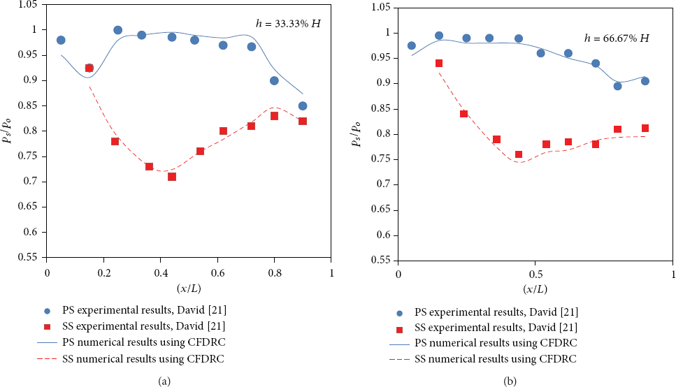
Comparison of surface pressure distributions at different blade height locations.
The current numerical results are in good agreement with the experimental data.
Blowing Ratio Effect on Pressure Side Average Overall Film Cooling Effectiveness.
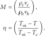
In general, regardless of hole shape and angle, film cooling effectiveness is found to increase with the blowing ratio. The blowing ratio and the film cooling effectiveness are defined as follows:
However, beyond a critical blowing ratio, film cooling effectiveness is found to decline. This decline can be attributed to the phenomena of film cooling lift-off, where film cooling jet fails to attach to the pressure side surface and penetrates into the mainstream. Figure 8 indicates that the film cooling effectiveness increases by increasing blowing ratio for different hole shapes up to M = 1. After this value film cooling effectiveness decreases by increasing blowing ratio for cylindrical and LFDCA-5-5 hole shapes as result of lift-off phenomena occurrence. But, for LFDCA-9.3-14.6 hole shape the lift-off phenomena do not appear due to the high value of forward angle which decreases the strength of counterrotating vortex pair of mixing flows.
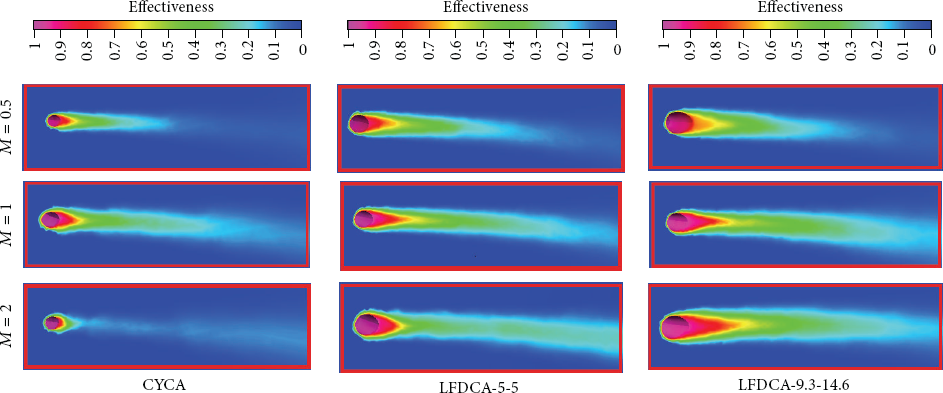
Fourth hole pressure side film cooling effectiveness of different hole shapes located at L/LPS = 0.25, with α = 60° and β = 0° at different blowing ratios.
Figure 9 indicates that the average effectiveness increases by increasing the blowing ratio up to unity. The average overall film cooling effectiveness is defined as follows:
Pressure side average overall film cooling effectiveness of different holes shapes located at L/LPS = 0.25, with α = 60° and β = 0° at different blowing ratios.

This value of blowing ratio is the peak value for CYCA and LFDCA-5-5 hole shapes. The average effectiveness associated with LFDCA-9.3-14.6 hole shape increases by increasing the blowing ratio up to approximately 2 as the high value of forward angle decreases the strength of counterrotating vortex pair of the mixing flows. This counterrotating vortex decreases the lift-off phenomena.
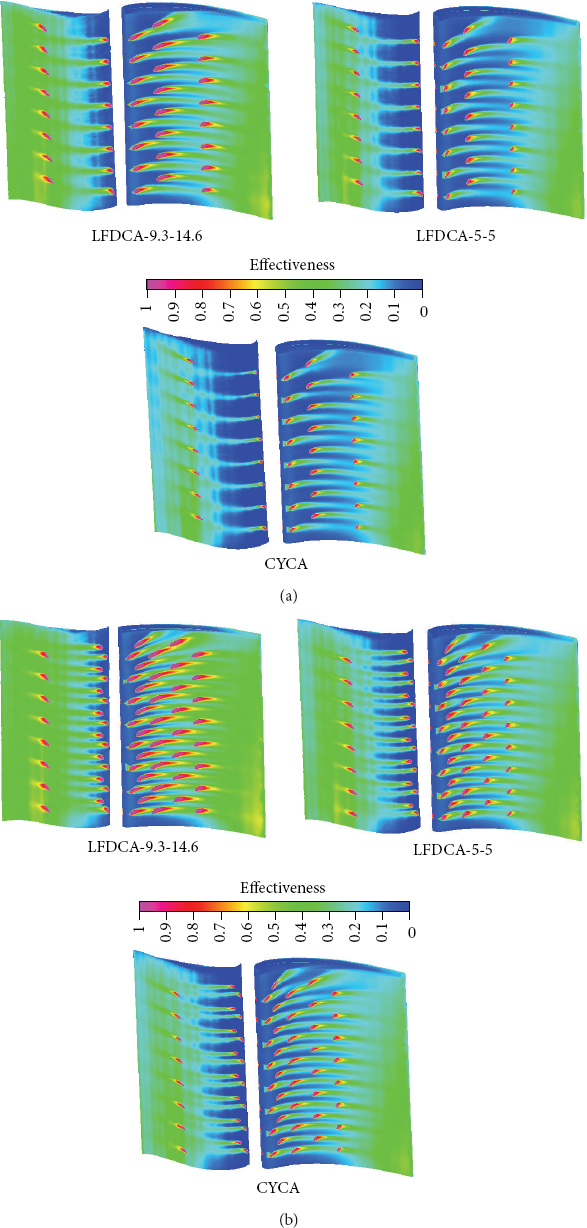
As shown in Figure 10, the maximum average effectiveness is associated with LFDCA-9.3–14.6 hole shape for different cooling array location. CYCA is more sensitive to cooling hole array location compared to the other shapes as the forward angle in the other shapes (LFDCA-5-5 and LFDCA-9.3–14.6) compensates for the drop in film cooling effectiveness due to the high surface curvature. When the film cooling holes array is located at the pressure side leading edge (L/LPS = 0.1), a small distance is cooled along streamwise direction due to the effect of high surface curvature at leading edge region. By increasing the location distance of film cooling hole array from leading edge, film cooling effectiveness is extended deeper in the streamwise direction due to the decrease in surface curvature in trailing edge direction. Thus, the lift-off decreases. So, more than one cooling hole array is needed at the pressure side leading edge for good cooling while low number of cooling holes arrays are needed in trailing edge direction.

Pressure side average overall film cooling effectiveness of different holes shapes with M = 1, α = 60°, and β = 0° located at different positions.
The direction of cooling flow injection on pressure side surface is very important for the cooling process. By decreasing the streamwise angle the momentum exchange between the mainstream flow and the cooling flow is increased. Thus, the film cooling effectiveness has been improved. The high forward angle of compound shape and curvature of pressure side surface causes a difficulty in injecting the cooling flow with streamwise angle smaller than 35°. Figure 11 presents film cooling effectiveness contours of different hole shapes with different streamwise angles. The maximum film cooling effectiveness is obtained at a streamwise angle α = 35°. The effectiveness is decreased by increasing the streamwise angle especially for CYCA hole shape with streamwise angle of 90°. The counterrotating vortex pair of cross flow is strong due to coolant momentum flux being normal to the pressure side surface which causes the cooling jet to separate from the surface. Therefore, lift-off occurs and the film cooling effectiveness decreases. This large mechanism structure reduces the exchange of the momentum and the heat transfer between the jet and mainstream flow. LFDCA-9.3–14.6 hole shape reduces lift-off with streamwise angle of 90°.

Pressure side film cooling effectiveness of different hole shapes at cutting plane located at the fourth hole from the blade tip with different streamwise angles.
The structure of the film cooling flow is examined to study the effect of counterrotating vortex pair (CRVP) on the film cooling. Traditionally, the coolants momentum flux ratio is thought to be the most critical parameter for film cooling effectiveness. However, the index of film cooling performance is also influenced notably by counterrotating vortex pair. The sources of CRVP are the in-tube vortex, the in-tube boundary layer vorticity, and the jet/mainstream interaction effect alone or combined. By simulating a general inclined cylindrical cooling hole on a turbine pressure side, the CRVP is visualized as well as the interaction of mainstream and coolant stream tubes as indicated in Figure 12. This figure presents the stream tubes of different streamwise angle of CYCA with different blowing ratio. The jet/mainstream interaction is the only essential source of counterrotating vortex pair. At blowing ratio of 1 and streamwise angle of 35°, good mixing between the mainstream and coolant flow due to the counterrotating vortex pair. No lift-off is noticed which results from the impulse of the jet on the crossflow The wake-vortices formed are weak The strength of the counterrotating vortex pair increases by increasing the streamwise angle. At streamwise angle 90°, the counterrotating vortex pair is strong due to high coolant momentum flux in vertical direction to pressure side surface which causes the cooling jet to separate from the surface. Therefore, lift-off occurs and the film cooling effectiveness decreases.

Stream tubes for CYCA cooling hole on pressure side surface with cooling holes array located at L/LPS = 0.25, M = 1, and zero spanwise angle at different streamwise angles.
Figure 13 presents the variation of pressure side average effectiveness versus the streamwise angle of different hole shapes. The maximum average effectiveness is obtained with LFDCA-9.3–14.6 hole shape. Lift-off on the pressure side is decreased for higher forward angle. In addition, by increasing the streamwise angle, the counterrotating vortex pair of cross-flow becomes strong.

Pressure side average overall film cooling effectiveness of different holes shapes located at L/LPS = 0.25 with β = 0°and M = 1 with different streamwise angles.
One of the important parameters which changes the film cooling effectiveness is the spanwise angle. This angle increases the film cooling effectiveness by increasing the cooling area in the spanwise direction. This increase is associated with a decrease in the cooling area in streamwise direction. In addition, changing the hole shape affects the cooling area as well. As shown in the Figure 14 for CYCA hole shape, the film cooling effectiveness is improved by increasing the spanwise angle, but in small value due to a small increase in spanwise cooling area. The importance of spanwise angle appears significantly with LFDCA shape. For LFDCA-5-5 hole shape the average effectiveness increases by increasing spanwise angle, especially with β = 60°. By increasing spanwise angle using LFDCA-9.3-14.6 hole shape, the cooled area in spanwise direction increases for the case of β = 30°. More increase of the cooling area is obtained for β = 60° while a small cooling zone area is obtained in the streamwise direction. The average effectiveness decreases but it is still better than the average effectiveness associated of zero spanwise angle. Therefore, good cooling can be obtained for low number of cooling holes and high number of cooling arrays.
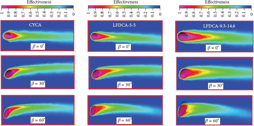
Pressure side film cooling effectiveness of the fourth hole from the blade tip of different hole shapes with different spanwise angles.
It is clear from the Figure 15 that average effectiveness associated with LFDCA hole shape increases by increasing the spanwise angle compared to CYCA hole shape. The maximum effectiveness is obtained with LFDCA-9.3-14.6 hole shape.
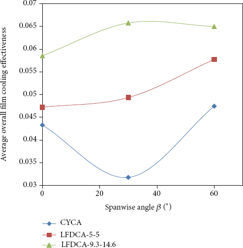
Pressure side average overall film cooling effectiveness of different hole shapes located at L/LPS = 0.25 with α = 60° and M = 1 with different spanwise angles.
Blowing Ratio Effect on Suction Side Film Cooling Effectiveness.
Figure 16 indicates that film cooling effectiveness increases by increasing blowing ratio. The effectiveness on the pressure side surface increases positively with the blowing ratio up to a blowing ratio of one. Then, the film cooling effectiveness decreases by increasing blowing ratio beyond one. For convex curvature (suction side surface), the lift-off is decreased due to the Coanda effect, which acts to spread out the coolant through adherence of the jet to the surface and keeps the jet adhered at higher momentum flux ratios. In addition, the associated film cooling effectiveness at low value of blowing ratio has a small value for different hole shapes. The effectiveness increases significantly by increasing blowing ratio. The use of compound hole shape (simple hole shape with spanwise angle) increases the effectiveness more than the cylindrical hole shape (CYCA). The optimum effectiveness is associated with LFDCA-9.3-14.6 hole shape where high forward angle decreases the strength of counterrotating vortex pair of mixing flows and consequently decreases lift-off in addition to Coanda effect.

Suction side film cooling effectiveness of different hole shapes located at L/LSS = 0.25, with α = 60° and β = 0° at different blowing ratios.
As shown in Figure 17 the suction side average effectiveness increases by increasing the blowing ratio. The best average effectiveness is obtained for the LFDCA-9.3-14.6 hole shape at different values of the blowing ratios. As mentioned earlier, higher values of forward angle decrease the strength of the counterrotating vortex pair of mixing flows which in turn decrease the lift-off phenomena.
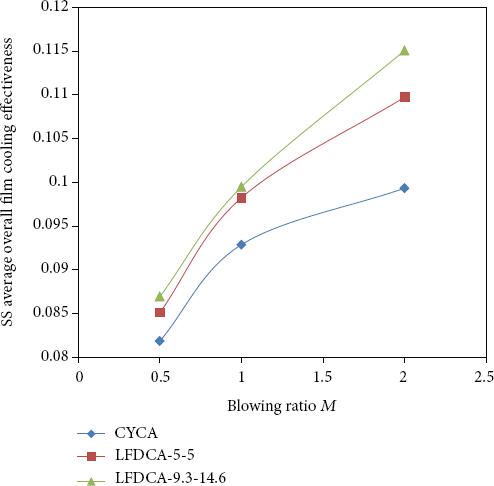
Suction side average overall film cooling effectiveness of different holes shapes located at L/LSS = 0.25, with α = 60° and β = 0° at different blowing ratios.
The effect of hole position on pressure side (concave) is similar to suction side (convex). But, the film cooling effectiveness on the suction side (convex) provides better coverage at higher blowing ratios by resisting jet penetration into the mainstream in comparison with pressure side (concave) and flat plate effectiveness values due to the Coanda effect. The different hole configurations on the convex surface have an effect also on the film cooling performance. A low improvement was observed in effectiveness on the convex surface due to using LFDCA holes instead of CYCA holes at suction side leading edge, while the effectiveness remains nearly unchanged in the trailing edge direction, as shown in Figure 18. When the film cooling holes array is located at the suction side leading edge (L/LSS = 0.1), a small change in the film cooling effectiveness is observed along the streamwise direction due to the effect of high surface curvature at leading edge region. By increasing the location distance of film cooling hole array from leading edge, film cooling effectiveness extended deeper in the streamwise direction due to the decrease in surface curvature in trailing edge direction which decreases lift-off. So similar to pressure side, more than one cooling hole array is also needed at the suction side leading edge for good cooling, and low number of cooling holes arrays are needed in trailing edge direction and this number is lower than the needed number at pressure side as Coanda effect.

The fourth hole pressure and suction sides film cooling effectiveness of simple and compound hole shapes with M = 1, α = 60°, and β = 0° located at different positions.
Figure 19 presents the variation of suction side average effectiveness versus the film cooling holes array location; as shown in the figure a low improvement was observed in average effectiveness on the convex surface due to using LFDCA holes instead of CYCA holes at suction side leading edge, and the effectiveness does not change in the trailing edge direction. For all shapes of the holes, the average effectiveness increases by increasing L/LSS where low surface curvature exists near in the trailing edge region.
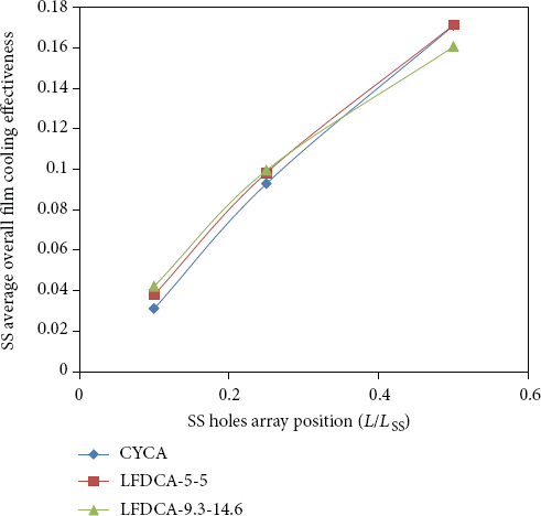
Suction side average overall film cooling effectiveness of different holes shapes with M = 1, α = 60°, and β = 0° located at different positions.
Figure 20 presents effectiveness contours on the suction side surface of different streamwise angles. The effect of streamwise angle on suction side film cooling effectiveness is reduced due to the Coanda effect which spread the coolant distribution by adhering the jet to the surface and keeps the jet attached for higher momentum flux ratios. The existent of forward angle of compound shape improves the effectiveness by reducing the lift-off, so the best effectiveness was obtained with LFDCA-9.3-14.6 hole shape followed by LFDCA-5-5 and the worst effectiveness with CYCA at streamwise angle 25°. By increasing the streamwise angle the film cooling effectiveness associated with different hole shapes decreases with small value due to the Coanda effect.

Suction side film cooling effectiveness of different hole shapes at cutting plane located at the fourth hole from the blade tip with different streamwise angles.
Figure 21 presents the variation of suction side average effectiveness versus streamwise angle. As shown in Figures 19 and 20, the average effectiveness decreases with a small value by increasing streamwise angle.

Suction side average overall film cooling effectiveness of different holes shapes located at L/LSS = 0.25 with β = 0° and M = 1 with different streamwise angles.
Figure 22 indicates that increasing the spanwise angle up to β = 30° for different hole shapes decreases the streamwise cooling area and increases the span-wise cooling area. The high increase in the spanwise angle (β = 60°) is associated with a high spanwise cooling area which clearly decreases the overall effectiveness especially for LFDCA.

Suction side film cooling effectiveness of the fourth hole from the blade tip of different hole shapes with different spanwise angles.
Figure 23 presents the variation of suction side average effectiveness versus the spanwise angle. It is clear from the figure that average effectiveness associated with LFDCA holes and CYCA hole shapes is increased by increasing the span-wise angle up to β = 30°. After this value the average effectiveness decreased by increasing the spanwise angle because a high value of spanwise angle gives a low streamwise cooling area but with high spanwise cooling area which minimizes the average effectiveness especially for LFDCA where the cooling flow cannot reach the blade surface with this shape.

Suction side average overall film cooling effectiveness of different holes shapes located at L/LSS = 0.25 with α = 60° and M = 1 with different spanwise angles.
Multi-Cooling Holes Arrays Geometry.
One cooling holes array on pressure or suction sides is not enough for turbine blade cooling. One cooling hole array on pressure or suction side is just used to study the performance of blade cooling on concave and convex surfaces with different hole shapes at different streamwise and spanwise angles, blowing ratios, and hole positions. This numerical investigation of the one cooling array is performed to predict suitable optimum LFDCA shapes. Then, a suitable number of cooling arrays on the two sides of the turbine blade are determined. The results indicated that pressure side needs more cooling holes arrays than suction side. In addition, a larger number of cooling arrays are required on the pressure and suction sides leading edge. The investigations presented in the current study are performed using an actual turbine blade with two different cooling arrays. In case 1, film cooling on the turbine blade is achieved using three-stagger cooling arrays on the pressure side and two stagger cooling arrays on the suction side, while in case 2, film cooling on the turbine blade is done with five-stagger cooling arrays on the pressure side and three-stagger cooling arrays on the suction side. In the two cases, each array contains eight holes. The shape and number of cooling holes for each array and its positions from the leading edge of different cases are presented in Table 1. The distribution of the cooling holes is shown in Figure 24.
Multi-LFDCA-9.3-14.6 cooling holes arrays on pressure and suction sides.
Figure 25 indicates that the local film cooling effectiveness is enhanced on the pressure side surface especially on the leading edge by increasing the number of cooling arrays where high curvature of leading edge exists. The lifted-off coolant flow results in a reattachment behind the trailing edge. But, the cooling effectiveness on the suction side is enhanced using a lower number of cooling holes arrays compared to pressure side due to the Coanda effect. It extends the cooling flow deeper toward the trailing edge without lift-off. The pressure side cooling effectiveness is higher than that of the suction side due to the usage of high number of cooling holes arrays on the pressure surface with less area compared to suction side area. The usage of LFDCA-9.3-14.6 hole shape on the turbine blade enhanced the film cooling compared to other shapes as presented in Table 1. Figure 25(a) indicates that the trailing edge region, especially with LFDCA-9.3-14.6 hole shape, is covered with the cooling flow but the leading edge area still needs more cooling arrays in order to have an appropriate cooling. By increasing the number of cooling arrays as shown in Figure 25(b), the cooling flow covers the overall areas of pressure and suction sides. Good turbine blade cooling is obtained with the usage of LFDCA-9.3-14.6 hole shape on both the blade sides. The results of the film cooling effectiveness on the two sides of the blade for two different cases are presented in Table 2.
The engine performance is affected by the amount of bleed air that is used for the turbine cooling. Therefore, it is required to determine the minimum amount required for efficient blade cooling. A numerical investigation is performed to determine the coolant mass flow rate for different cooling holes numbers, shapes, and directions of coolant injected. The total amount of coolant mass flow rate can be calculated using the following expression:
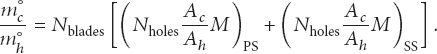
The turbine rotor is assumed to have 30 blades of different hole shapes which are presented in Table 1. The ratio of cooled to hot mass flow rates is presented in Table 3.
Pressure and suction sides cooling holes arrays numbers, shapes definition, and positions.

Pressure and suction sides’ average effectiveness.

Turbine blade cooled to hot mass flow ratio for different hole shapes.

Figure 26 presents the variation of pressure side and suction side average film cooling effectiveness versus the mass flow ratio. The results indicate that increasing the mass flow ratio enhances the film cooling effectiveness on the pressure and suction sides up to mass ratio of 2.1. Pressure side film cooling effectiveness decreases with small value by increasing mass flow ratio over 2.1. Suction side effectiveness increases slightly by increasing mass flow ratio over 2.1 due to the Coanda effect on the convex surface. So, the effectiveness with mass flow ratio of 2.1 is considered enough for efficient cooling.

Variation of average film cooling effectiveness with mass flow ratio of optimum cooling holes system presented in Table 1, case 2.
The film cooling effectiveness on the pressure and suction sides of the turbine blades is affected by the rotational speed. While the film cooling is designed at a blade rotational speed of 9600 rpm, the turbine operates at different rotational speeds during the off-design operations.
The performance of this multi-cooling hole arrays is studied at different off-design rotating conditions. The results presented in Figure 27 indicate that for rotational speeds lower than the design speed, the effectiveness of the film cooling is enhanced on the suction and pressure sides of the blade because the Coanda effect broadens the coolant at the lower rotational speeds, while the cooling effectiveness decreases at higher rotational speeds due to the existence of the lift-off phenomena.
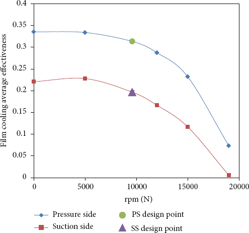
Variation of the film cooling average effectiveness with the blade rotational speed.
In the current work, a parametric study is performed for the film cooling on GE-E 3 turbine blade. The effect of film cooling parameters such as lateral and forward diffusion angles (hole shape), blowing ratio, streamwise angle, span-wise angle, and hole position on the cooling effectiveness is studied and optimum cooling parameters are selected. Unstructured finite volume technique is used to solve the steady, three-dimensional, and compressible Navier-Stokes equations. K-ε turbulence model is used in the simulations. The results indicate that the average film cooling effectiveness on the blade pressure side is enhanced by increasing the blowing ratio for different hole shapes up to M = 1. After this value, film cooling effectiveness is decreased by increasing blowing ratio for cylindrical and LFDCA-5-5 hole shapes as a result of the lift-off phenomena. For LFDCA-9.3-14.6 hole shape, the lift-off phenomena do not appear due to the high value of forward angle. Preventing lift-off due to Coanda effect on convex curvature (suction side surface) increases the film cooling effectiveness by increasing blowing ratio for different hole shapes. Due to the surface curvature of concave and convex sides, more than one cooling hole array is needed at the pressure and suction side leading edge for good cooling. Lower number of cooling hole arrays are needed in the trailing edge direction. The average film cooling effectiveness decreases by increasing the streamwise angle on pressure and suction sides, especially for CYCA hole shape with streamwise angle of 90°. The use of LFDCA-9.3-14.6 hole shape on the turbine blade improves the cooling effectiveness regardless of the value of the streamwise angle, the blowing ratio, and the hole positions. Five-stagger cooling arrays on the pressure side and three-stagger cooling arrays on the suction side with LFDCA-9.3-14.6 hole shape are enough for efficient cooling of the two sides and a 2.17% bleed air is needed for the cooling process.
Footnotes
Nomenclature
Greek Symbols
List of Abbreviations
The authors declare that there is no conflict of interests regarding the publication of this paper.