
Abstract
Planetary gear trains (PGTs) are introduced to undergraduate mechanical engineering students in the course of Theory of Machines. The complexity of the traditional methods for analyzing PGTs has kept many from becoming familiar with the capability of PGTs in mechanisms and machine design. In this paper a unified general formulation for simultaneously visualizing velocities, torques, and power flow through a train is presented on a single nomograph. Therefore, the increasing complex mechanical systems, such as automotive transmissions, are much easier to understand. Nomographs of Fundamental Gear Entities (FGEs) are constructed based on the nomographs of their fundamental circuits, without specifying the exact gear dimensions. They are then unified in one system nomograph. Nomographs are promising to provide designers with an efficient tool for the design of geared mechanisms.
1. Introduction and Literature Review
Epicyclic gear trains (EGTs) are commonly used in automatic transmission mechanisms to achieve a set of desired velocity ratios [1]. Figure 1 shows an epicyclic gear mechanism employing the Ravigneaux gear set as the ratio change gear train where the rotating and band clutches are designed as C and B, respectively. The velocity ratios selected for a transmission are tailored for vehicle performance. Typically, they include a first gear for starting, a second or third gear for passing, an overdrive for fuel economy at road speeds, and a reverse [2]. Table 1 shows the clutching sequence for the transmission shown in Figure 1.
Clutching sequence for the transmission shown in Figure 1.

For downhill braking only.

A typical automatic transmission mechanism.
For the kinematic analysis of EGMs, various approaches such as the relative velocity method [3–5], energy method [6], bond graph method [7], vector-loop method [8, 9], and the nomograph method [10–12] have been proposed. Freudenstein and Yang [13] introduced the concept of fundamental circuit to analyze EGTs. The concept was further extended by other researchers [14, 15]. The concept of fundamental circuit is a powerful tool for automated analysis of EGTs. In addition, some other studies have concentrated on structural and dimensional syntheses [16–21].
A practical approach uses a lever analogy [22] that translates a planetary gear set to a lever of certain amount of nodes. For instance, a single plane of gears (single-planet or double-planet gear sets) can be represented by a lever with three nodes representing the sun gear, internal gear, and the carrier, whose linear velocities are analogous to the angular velocity of the respective component in the actual planetary gear train. Any one-degree-of-freedom planetary gear train can be reduced into a single lever to allow easy calculation of speeds, but the calculations must still be carried out manually. In addition, the planet rotational speeds, which are not included in level analogy, must still be determined using the conventional methods.
The studies on power flow analysis of EGMs are mostly done in the context of efficiency formulations [14, 23, 24]. Pennestri and Freudenstein [14, 24] use the same fundamental circuits proposed earlier [13] for a complete static force analysis [23]. They apply a similar formulation in conjunction with their earlier kinematic study [2] to determine the most efficient kinematic configuration. The work by [25] further generalizes the efficiency formulations of gear trains formed by single- or double-planet arrangements. A review of formulas for the mechanical efficiency analysis of two-degrees-of-freedom epicyclic gear trains is presented by Pennestri and Valentini [26].
Reference [10] used a practical approach to investigate both the angular velocities and the torques acting on the first and last gears and the carrier of a train depending on nomographs. The origins of nomographs date back to Professor Maurice d'Ocagne in the late nineteenth century. This technique was first applied by Toyota to investigate their Toyota Hybrid System [11]. Toyota's solution is not a general, concise solution technique. It is only an application to their case. No details are given as to how nomographs can be drawn and where axes are to be placed. Toyota uses the three parallel axes nomograph in a different manner to that used by [10].
A methodology for construction of the kinematic nomograph of an FGE and/or an EGM in terms of the gear ratios of its gear pairs was recently developed by [12]. First, the well-established graph theory is used to represent the system and then to detect the fundamental geared entities (FGEs). Then, nomographs of FGEs are constructed, without specifying the exact gear dimensions. Finally, the nomographs of the FGEs are unified in one system nomograph. The new method for constructing nomographs has the following advantages above Corey's method:
A nomograph can be constructed using more than three vertical parallel axes. It gives the angular velocities of all the links of an epicyclic gear train including the planet gears.
The locations of axes are chosen according to the fundamental circuits equations.
It is applicable to any epicyclic gear train including compound ones and how complex they are.
It relays on the recent graph theory, the concept of fundamental circuit, and the concept of fundamental geared entity [18].
An important feature of the suggested approach for constructing multiaxis nomograph is the ability to enumerate the clutching sequences associated with epicyclic-type automatic transmission mechanisms [27] and to establish the torque relations among these coaxial links in order to effectively compute the power flowing through a transmission mechanism. Not all links of a more than three link epicyclic gear train could be incorporated in a three-axes nomograph which makes the enumeration of clutching sequences using such nomographs impossible. It makes also the study of the velocity and torque relations for links other than the first and last gears and carrier impossible too.
Due to the fact that the function of a transmission mechanism is to provide proper torques and velocities for a vehicle, it is essential to identify the relations among the velocity ratio, torque distribution, and the power flow in it.
A unified general formulation for computing velocities and torques of the links of any planetary gear train is still not currently available.
In this paper, we develop a methodology to achieve this goal. The methodology is based on multiaxes nomographs of planetary gear trains [12] and on the concept that any PGT is a combination of several fundamental geared entities [17] that in turn consist of several fundamental circuits. It is applicable to one- and multi-degree-of-freedom PGTs. Only one-degree-of-freedom PGTs will be considered in this paper. The analysis of geared mechanisms has been nearly perfected; the challenge lies in proposing new simplified methods and subsequent clear visualization of the rotational velocities, torques acting on the EGMs, and power flow through the train. A simplified method is presented in this work for analyzing and characterizing gear trains to be used for teaching PGTs in the course of Theory of Machines.
In what follows, the concept of a fundamental circuit will be reviewed.
2. Fundamental Circuit
Structural synthesis of gear drives by means of graph theory has been an important area of investigation in the field of kinematics. Pioneer analyses on the kinematic structure of mechanisms using graph theory are due to Freudenstein and his coworkers [28, 29]. The most important, which has been extensively used in subsequent papers, is that a geared kinematic chain (GKC) can be represented by means of a planar graph satisfying characteristic topological conditions [20].
In a graph representation of an EGT [16], links are represented by vertices, and joints are represented by edges. The gear joints are represented by thick edges, revolute joints are represented by thin edges, and the thin edges are labeled according to their axis locations in space.
The fundamental circuit is defined as a circuit consisting of one geared edge and several turning pair edges connecting the endpoints of the geared edges. Figure 2(a) shows a gear pair which consists of two gears, ga and gb, and a supporting carrier, c. Figure 2(b) shows the corresponding graph representation, which is a fundamental circuit. Figure 2(c) shows the schematic representation of a fundamental circuit. This schematic diagram consists of a block, three nodes, and three chords.
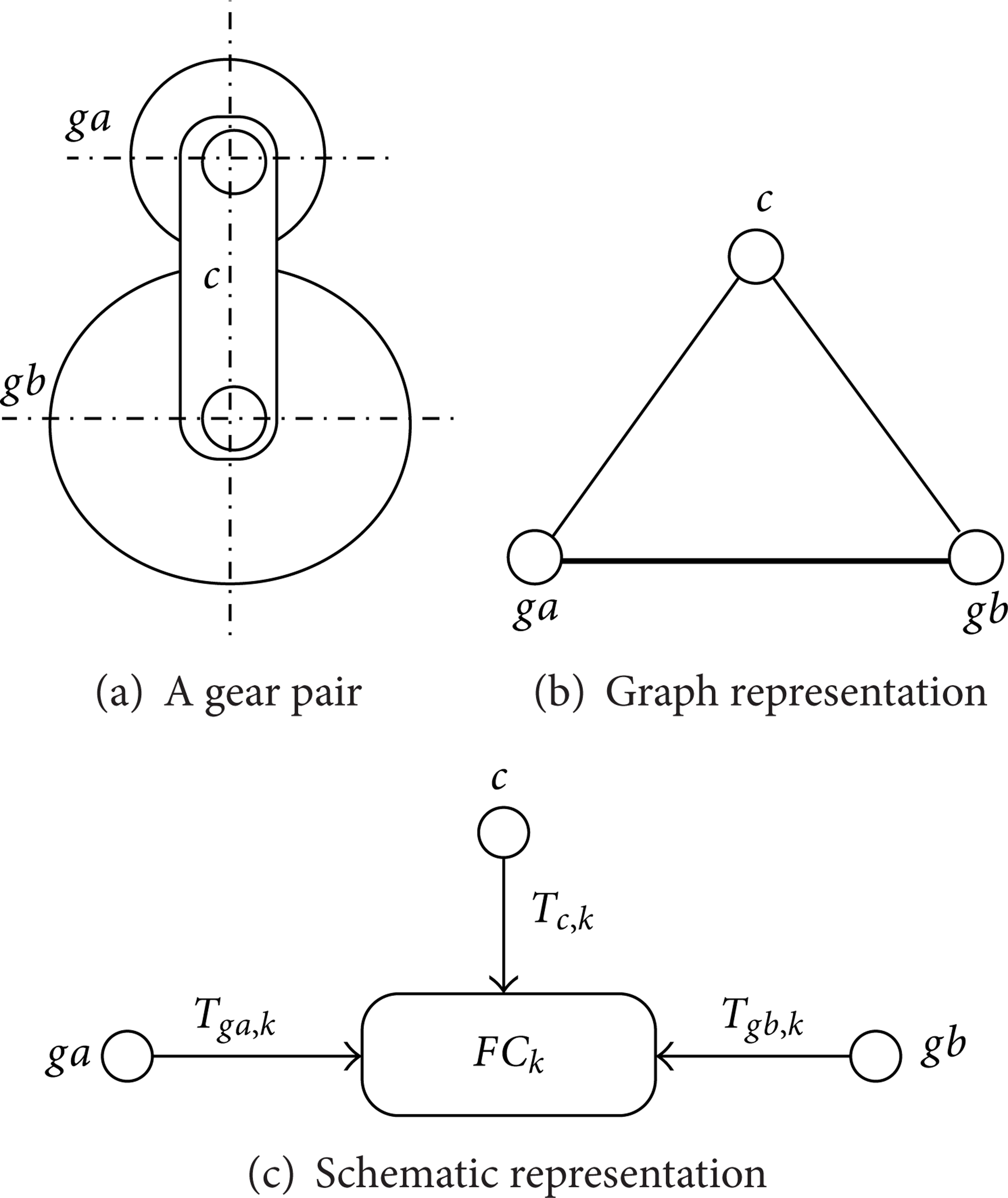
A basic gear pair and its graph and schematic representation.
The block represents a fundamental circuit. The symbol FC k denotes the kth fundamental circuit of an EGT. The nodes represent the links of the fundamental circuit which transfer power or torque to the other fundamental circuits. The chords connecting the nodes to the block are labeled with T ga, k , T gb, k , and T c, k which denote the external torques exerted on links ga, gb, and c, respectively, positive counter clockwise.
The term “gear ratio” is used to denote the ratio of a meshing pair, while the term “velocity ratio” is used to denote the velocity ratio between the input link and the output link of an EGM.
Considering the kinematic of a fundamental circuit, the fundamental circuit equation can be written as [16]

where ω ga , ω gb , and ω c denote the angular velocities of a gear pair ga and gb and its carrier c, respectively, and N gb, ga denotes the basic gear ratio

where Z gb and Z ga denote the numbers of teeth on the gears b and a, respectively, and the positive or negative sign refers to the internal and external gear pairs, respectively.
3. Torque Analysis of Fundamental Circuit
For a fundamental circuit of an EGT shown in Figure 2, it is well known that under static equilibrium, torques acting on the three links of a fundamental circuit must be summed up to zero:

It is also well known that under constant-velocity operation and in the absence of friction, the net power passing through a fundamental circuit is zero. Power is the product of torque and angular velocity (T · ω):

Solving (1), (3), and (4) yields

Equations (5) and (6) express two of the external torques in terms of the third. The word “external” refers to all sources that are external to the gear pair of interest. Thus, external torques come from all the links that are connected to links ga, gb, and c whether with gear pairs or turning pairs having axes at levels different from that of the axes of gears ga and gb.
4. Nomograph for Velocity, Torque, and Power Flow Analysis
Nomograph is defined as three or more axes, or scales, arranged such that problems of three or more variables can be solved using a straightedge [12]. In the particular case of EGTs, a nomograph can be constructed using three vertical parallel axes [10, 11] or three or more vertical parallel axes [12].
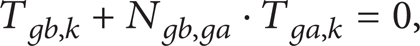
Equation (1) can be rewritten for the links of the fundamental circuit shown in Figure 2 as follows:
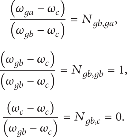
These values have been used to place the axes of the nomographs shown in Figure 3. The ω c axis passes at the origin, and also the ω gb axis is one unit apart from the ω c .
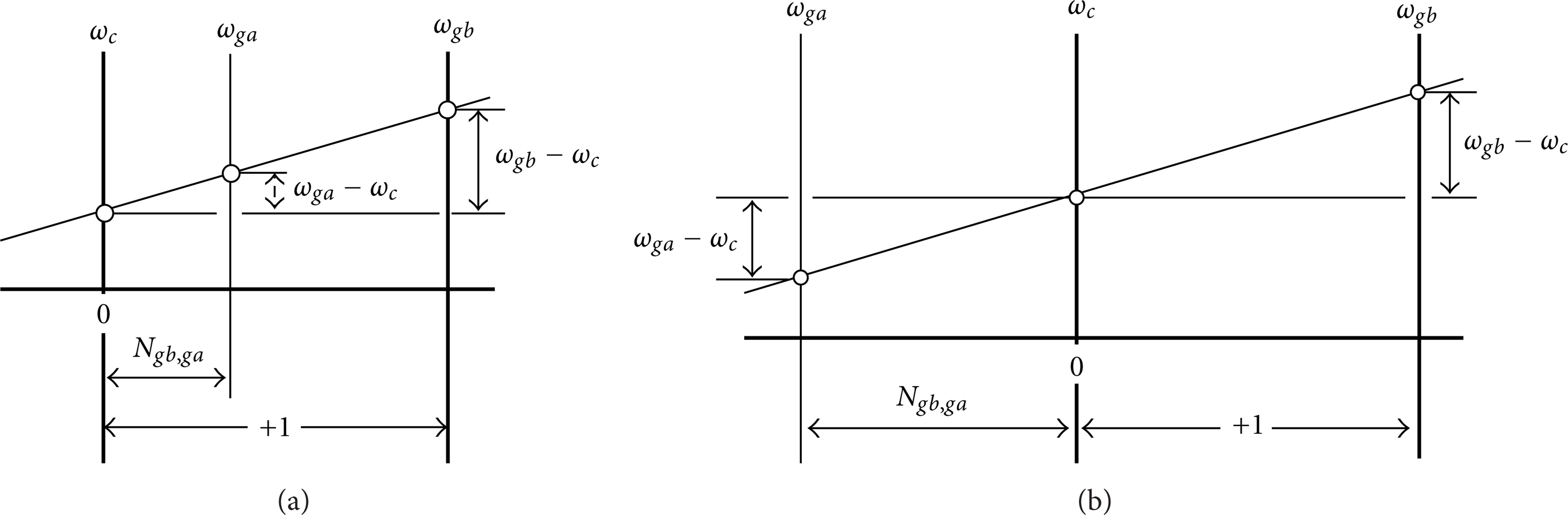
Nomographs for fundamental circuits with (a) internal gear pair and (b) external gear pair.
Figure 4 shows the torques T ga, k , T gb, k , and T c, k for the kth fundamental circuit of an EGT represented as arrows perpendicular to the three FC axes at the points representing the rotational speeds. Any straight line through the operating velocities of a fundamental circuit will intersect the horizontal axis, which connect the zeros of the three axes at point (e), a distance E from the origin. The moment of any torque vector about the zero of its rotational speed axis represents the power flowing in that branch (T · ω).
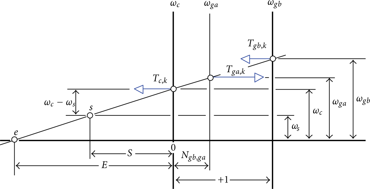
Nomograph for the fundamental circuit shown in Figure 3(a) with torques represented as vectors perpendicular to the rotational speed axes.
In general, from Figure 4, we can write
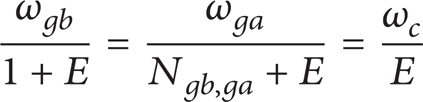
from which

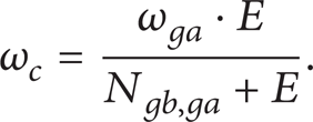
Substituting (9) and (10) into (4), multiplying by (N gb, ga + E), and simplifying we get

Perhaps it is more convenient to represent the torque vectors as arrows along the three axes as shown in Figure 5. Therefore, (11) is equivalent to summing moments of the torque vectors about point e.

Nomograph of a fundamental circuit with torques represented as vectors along the three axes.
Upward torque vector is assumed to have positive sign. Power flowing in the system is assumed to have positive sign also. Therefore, any torque vector pointing away from zero is representative of power flow in the system.
After more simplification of (11), we arrive at

Substituting (3) into (12) yields (5). Equation (5) is equivalent to summing moments of the torque vectors about the ω c axis.
Equation (5) implies that the torque vectors T ga, k and T gb, k must have opposite directions. If torque T ga, k points upward, then T gb, k must point downward.
Summing moments of the torque vectors about the ω gb axis will yield (6). Equation (6) implies that the torque vectors T ga, k and T c, k must have opposite directions.
Equations (5) and (6) together imply that the torque vectors on the two extremes of a fundamental circuit nomograph both must point upward or downward and that the third torque vector must point to the opposite direction.
Summing the torques in the y-direction will yield (3).
Most important is summing moments of torque vectors about any point (s) on the straight line through the operating velocities of the fundamental circuit shown in Figure 4; this will yield (4):

After these examinations, one finds that the torques shown in Figure 5 can be solved for in the same way as forces on a rigid beam may be solved for.
5. Nomographs of FGEs and/or EGMs
Canonical graph representation [17, 18] is used to analyze the topological structure of a mechanism. The canonical graph representation of the EGM shown in Figure 1 is sketched in Figure 6.

Canonical graph of the mechanism shown in Figure 1.
In a graph representation, the vertices can be divided into several levels. The ground-level vertex, called the root, denotes the casing. The first-level vertices denote the coaxial sun gears, ring gears, and carriers. The second- level vertices denote the planets. In Figure 6, link o is the ground-level vertex, links 1 through 4 are the first-level vertices, and links 5 and 6 are the second-level vertices. Label (a) denotes the common axis of the turning pair joints which join the first-level vertices and the ground-level vertex. Labels (b) and (c) denote the axes of the turning pair joints which join the second-level vertices and the first-level vertices. Labels G and g denote the internal and external gear joints, respectively. A literature survey reveals that all existing automatic transmission mechanisms have their links distributed up to the second level [1, 3]. In this paper, only those EGMs with their links distributed up to the second level will be considered.
Reference [17] defined the FGE as a mechanism represented by a subgraph formed by a single second-level vertex or a chain of heavy-edge connected second-level vertices together with all the lower vertices connecting them to the root. The FGEs can be categorized into single-planet FGE, double-planet FGE, triple-planet FGE, and so on.
The FGEs and EGMs having more than two planets in a chain are not practical and will be excluded from further consideration.
We now describe a step-by-step procedure for drawing an overall system nomograph of an EGM.
Step 1. Decompose the given EGM into several FGEs [2].
Step 2. Identify the fundamental circuits of each FGE.
Step 3. Draw a nomograph for each fundamental circuit as shown in Figure 5. There are three axes representing three links of a fundamental circuit.
Step 4. Connect the fundamental circuit nomographs at the appropriate points of connection according to the mechanism structural topology using the methodology developed recently by [12].
Step 5. Repeat Steps 3 and 4 for other FGEs.
Step 6. Unify the nomographs of all the FGEs in one system nomograph as [12].
It is apparent from Figure 6 that the Ravigneaux gear train is a double-planet FGE. Note that this FGE can itself serve as an EGM since it has four coaxial links at the first level. This gear train contains four fundamental circuits (5, 2, 3), (6, 5, 3), (6, 4, 3), and (6, 1, 3). Figure 7 shows the corresponding nomograph for this train in terms of planet gear 6 [12].
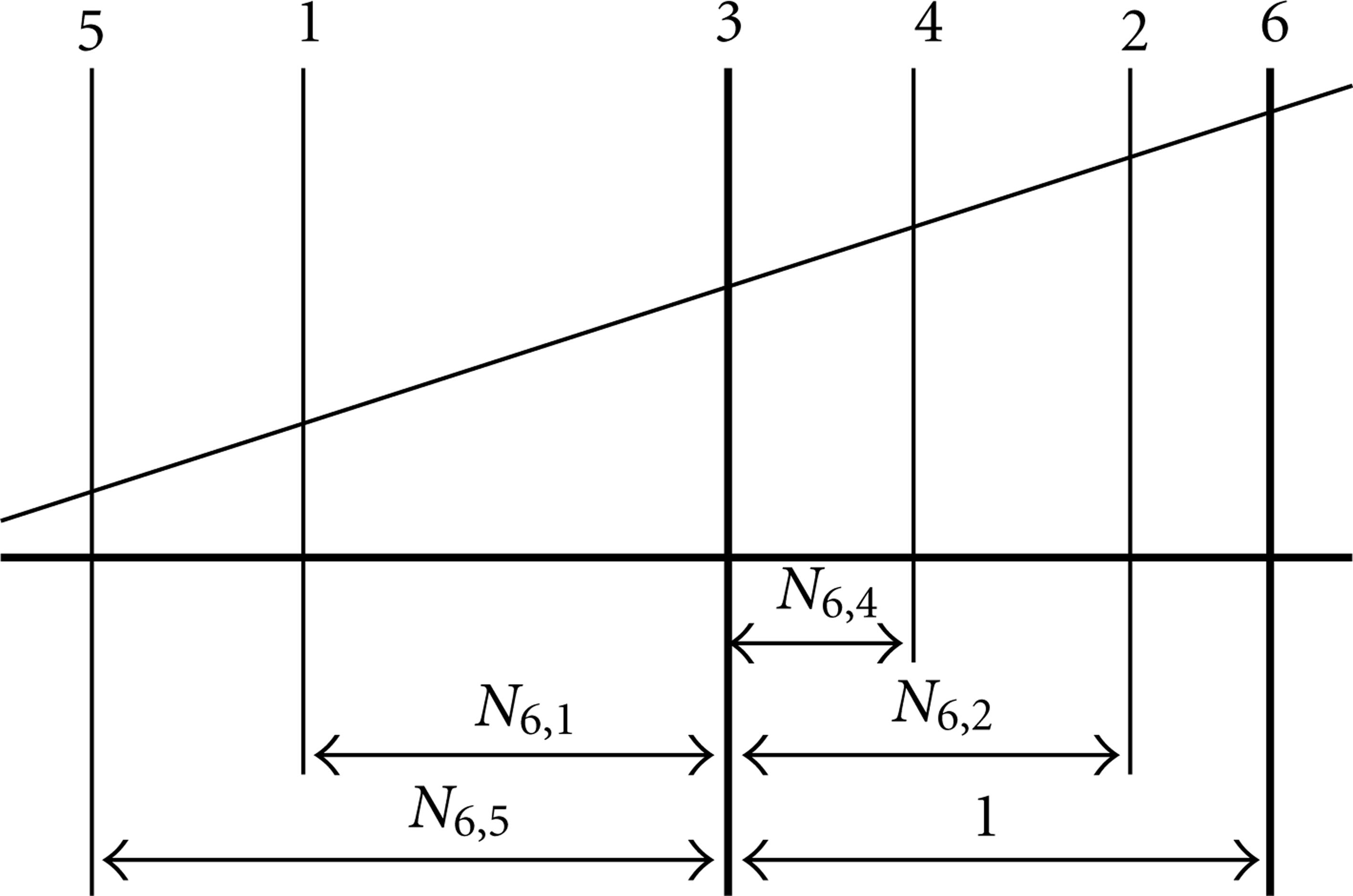
Nomograph for the double-planet FGT shown in Figure 1, in terms of planet gear 6.
6. Torque Analysis of FGEs and/or EGMs
Since only the first-level coaxial links of an EGM are used as the input, output, or reaction link, the torque relations among these coaxial links should be established in order to effectively compute the power flowing through a transmission mechanism. This can be accomplished by eliminating the torques of planets and inactive coaxial links (i.e., nontorque carrying links) from the fundamental circuit nomographs.
To facilitate the torque analysis, an overall system nomograph is drawn using the fundamental circuits as the building blocks as described in the preceding section, and then the torque vectors are drawn. The procedure is as follows.
Identify the input(s), output(s), and fixed links.
Draw torque vectors for each of the fundamental circuits.
At each link, impose the condition that the sum of torques acting on the link is equal to zero. Remember to include the input torque(s) T i , output torque(s) To, or reaction torque T r to the input(s), output(s), or fixed link, respectively.
Following the above procedure and since the sum of vector torques in the y-direction for each fundamental circuit equal zero, therefore, the sum of vector torques in the y-direction for all of the fundamental circuits will equal zero too. Also, since, for each fundamental circuit, the moment of the vector torques about any point (like point e or s) equal zero, therefore, the moment of the vector torques about any point, for all of the fundamental circuits, will equal zero too.
Although the E-value is a variable quantity that depends on the operating rotational velocities of the PGT, it allows early in the design process to visualize how the PGT is intended to react to typical PGT rotational velocities. The E-value variation with different input velocities has the distinct advantage of providing a clear visual representation of both the torque response of the PGT and the power flow through it.
To demonstrate and apply the approach, a design example is used to show how the velocities, the torques, and the power flow through the different clutching modes of the Ravigneaux gear train can be simultaneously visualized on a single nomograph.
7. Design Example
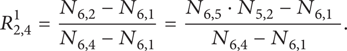
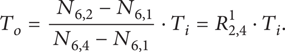
The gear mechanism shown in Figure 1 is known as the Ravigneaux gear mechanism. It is a double-planet FGE. Because there are four coaxial links and link four is preassigned as the output link, this gear train can provide six overall velocity ratios [12]. Traditionally, the velocity ratio is used to study the velocity relations among the different links of an EGT (see [2], e.g.). Let the symbol R x, y z denote the velocity ratio between links x and y with reference to link z, where x, y, and z are any three links in the gear train; then

Figure 7 shows the corresponding nomograph for this FGE in terms of the planet gear 6. The gear ratio for gear 2 that is not meshing directly with the planet gear 6 on which the nomograph is drawn, andits meshing with planet gear 5 can be found in terms of the gear ratio of the two planets N6,5 as

Kinematic relationships among the links of this FGE can easily be visualized by observation from the nomograph shown in Figure 7. Any straight line through the input operating velocities of the EGT will intersect other axes at the operating velocities of the links representing those axes. To compare the results of this methodology with others [2, 4–10], algebraic expressions for the velocity ratios of this FGE can be written as follows:


Substituting (15) into (18) yields

Also

From a single nomograph such as the one shown in Figure 7, all of the velocity ratios of the four coaxial links can easily be obtained.
The results are found in complete agreement with others [2, 4–10].
Case 1. Assume that link 3 serves as the fixed link, link 2 as the input link, and link 4 as the output link. The corresponding nomograph is sketched in Figure 8 without the planets axis. This nomograph corresponds to the first gear of the automatic gear transmission.

Nomograph for the Ravigneaux gear train without the planets axis when links 3, 2, and 4 are the fixed, input, and output links, respectively.
When the carrier is fixed (E = 0), the epicyclic gear train is transformed from epicyclic to ordinary gear train. Thus, kinematic nomographs which are valid for epicyclic gear trains can be extended to ordinary gear trains by assuming a proper fixed carrier to the ordinary gear train. Ordinary gear trains are epicyclic gear trains with E = 0.
To compare the results of this methodology with others [10, 13–15, 23–25], algebraic expressions for the torque relations can be written as follows.
Summing moments of the torque vectors about the ω3 axis yields

Substituting (18) into (23) and simplifying yield

Summing moments of the torque vectors about the ω4 axis yields

Substituting (18) into (25) and simplifying yield

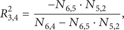
Case 2. Assume that link 1 serves as the fixed link, link 2 as the input link, and link 4 as the output link. The corresponding nomograph is sketched in Figure 9 where E = N6,1. This nomograph corresponds to the second gear of the automatic gear transmission.

Nomograph for the Ravigneaux gear train when links 1, 2, and 4 are the fixed, input, and output links, respectively.
Summing moments of the torque vectors about the ω1 axis yields

Substituting (22) into (27) and simplifying yield
Summing moments of the torque vectors about the ω4 axis yields

Substituting (22) into (29) and simplifying yield

Case 3. Assume that link 3 serves as the fixed link, link 1 as the input link, and link 4 as the output link. The corresponding nomograph is sketched in Figure 10 where E = 0. This nomograph corresponds to the reverse gear of the automatic gear transmission.

Nomograph for the Ravigneaux gear train when links 3, 1, and 4 are the fixed, input, and output links, respectively.
Summing moments of the torque vectors about the ω3 axis yields

Substituting (16) into (31) and simplifying yield

Summing moments of the torque vectors about the ω4 axis yields

Substituting (16) into (33) and simplifying yield

The results are found in complete agreement with others [10, 13–15, 23–25].
8. Conclusions
In this paper a unified general formulation for simultaneously visualizing velocities, torques, and power flow through a train is presented on a single nomograph. Therefore, the increasing complex mechanical systems, such as automotive transmissions, are much easier to understand.
It has been our instructional experience that the use of nomographs not only makes torque and speed calculations easy, but also improves students' ability to visualize the results and understand the effect of gear ratios. The present methodologies are promising to provide designers with an efficient tool for the design of geared mechanisms.