
Abstract
A PZT-based smart aggregate (SA) is capable of full process stress monitoring during earthquakes. A wired seismic monitoring system is prone to failure during earthquakes. Therefore, it is extremely necessary to use the wireless monitoring technique in the SA-based monitoring system. In this paper, the SA is integrated with the ZigBee wireless network which consists of a charge-to-voltage converter, a microprocessing unit, a wireless transmission unit, a base station, and a host computer. The dynamic loading scheme is applied on the SA and the output signal is measured by the wireless system and the wired system in parallel. The performance of the proposed wireless monitoring system is validated by comparing the wired and wireless signals. It is anticipated that this research will demonstrate the potential of using wireless monitoring systems for full damage process monitoring of concrete structures.
1. Introduction
In seismically active regions, acquisition of structural response data during earthquakes is essential to assist the evaluation of the current design practices [1]. Most of the existing seismic monitoring systems are based on the accelerometers [1–6]. However, damage detection using acceleration information is impractical due to the very heavy computational demands and the need for a detailed and accurate three-dimensional finite element model [2]. Thus, sensors that provide local damage information supplement the existing seismic monitoring systems nicely.
Traditional strain gauges like fiber Bragg Grating sensors and foil strain gauges, when embedded in a concrete structure, cannot measure the damage process reliably because their bondages with concrete tend to become loose. A commercially available load cell is able to measure the internal stress directly, but issues such as the size of the cell, its bondage with concrete, the interference it produces to the local stress field, and the cost hinder its application. The cement-based strain/stress sensors, which take advantage of the piezoresistivity effect developed by various researchers for internal stress/strain measurement [7–10], unfortunately can only be used when the building structure is in a uniaxial and elastic stress/strain state. A cement-based smart aggregate (SA) with a
All the above-mentioned monitoring systems are generally the wired system. However, this kind of system itself is also subject to failure during strong ground motions since it has many independent components, such as data loggers, sensors, and long cabling, which are very fragile. Thus, to acquire the full damage process information of a concrete structure during an earthquake event, it is extremely necessary to use the wireless monitoring system. Although many wireless monitoring systems have been developed for different types of structures [19–24], the architecture of the mentioned network differs greatly when the monitored structure types and structural parameters are different. Therefore, it is still worthy of a trial to integrate the SA with the existing wireless monitoring system.
2. Introduction of the Smart Aggregate
The structure of the SA used in this paper has been presented in the previous work of [18]. Figure 1 demonstrates its structure. The proposed SA consists of a piece of PZT patch connected with a piece of two-wire cable and a pair of marble blocks. The commercially available soft PZT ceramic referred to as P-5H with a major composition of Pb(TiZr)O3 was chosen. The PZT's properties, measured by the supplier, are listed in Table 1. Young's modulus of the marble and the epoxy was 51.5 GPa and 2.5 GPa, respectively, as supplied by the manufacturer. The size of the PZT patch was
Typical properties of the selected PZT P-5H.

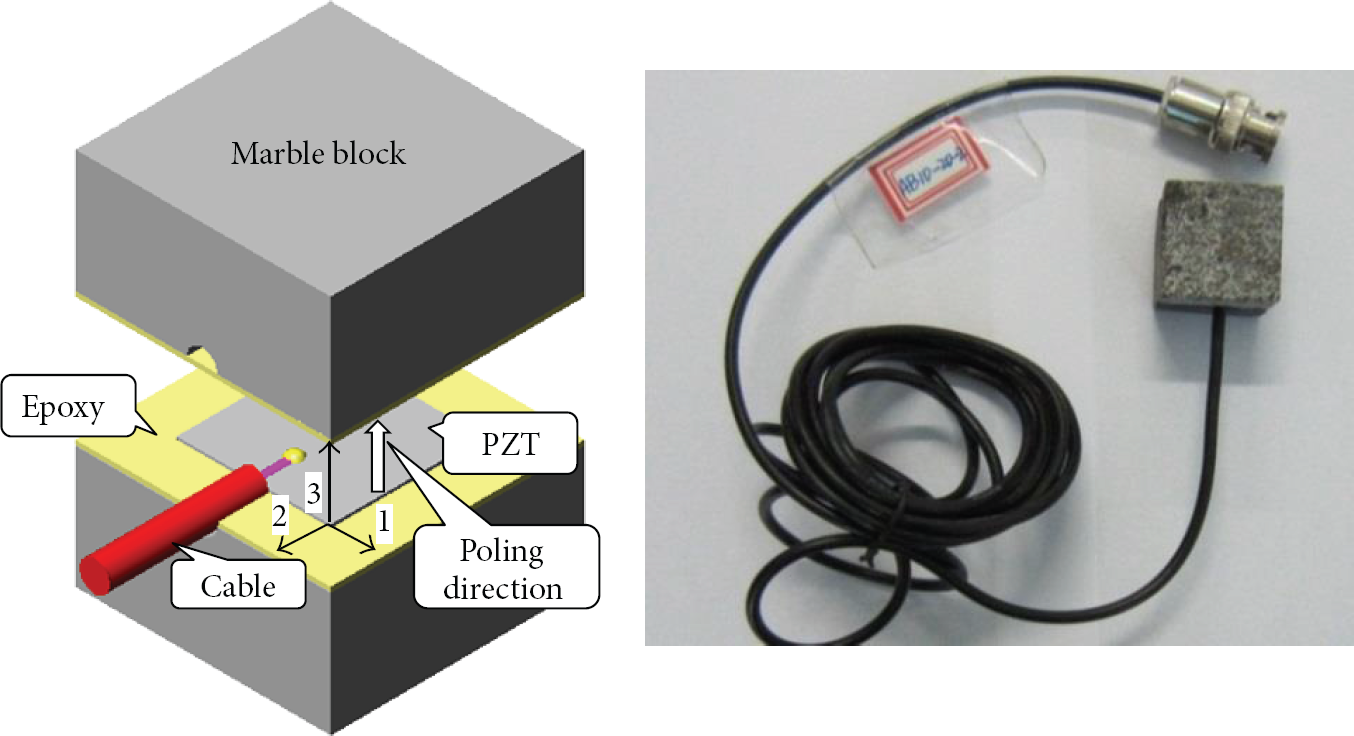
Structure of the smart aggregate and its photo.
3. Hardware of the Wireless Acquisition System
3.1. The Overall Architecture of the System
The charge signal generated by the SA was collected by the wireless monitoring system as shown in Figure 2. The system consists of a base station, a host personal computer, and several wireless nodes. The wireless network structure of this acquisition system used a star topology. Each node of the network was connected to the base station in a point-to-point manner. The communication among any two nodes in the star network was subject to the control of the base station. With such a system structure, it was easy to implement centralized control and, due to this characteristic, it also brought the advantages of safety and ease of maintenance.

Architecture of the SA-based wireless seismic monitoring system.
3.2. Design of Wireless Node
The wireless node collected the generated charge signals and transmitted them to the base station. Its structure is shown in Figure 3. The node used a modular design method, which included the flash storage unit, a wireless transmission unit, a microprocessing unit, and a power management unit.

Structure of wireless node.
3.3. Microprocessing Unit
The microprocessing unit that contains the analog-to-digital (AD) converter, timer function, channel selection, and other modules' drivers was also responsible for data preprocessing and system activation or hibernation. In addition, it also integrated embedded programs used to transfer data and commands between the node and the coordinator. In this design, TI high-performance 16 bit MSP430 was used in the microprocessing unit. Not only did it run efficiently, but also the power consumption was very low, which met the power requirements of the wireless network system.
3.4. Flash Storage
The storage used Nand flash which has the advantages of large capacity and can be read and written at a fast speed. In this system, it could be used to store the data obtained by timing acquisition and also could be used for the interim storage of other data.
3.5. Wireless Transmission Unit
The wireless transmission unit was in charge of sending and receiving orders or data. It used the CC2520 + CC2951 modules that can realize a long-distance data transmission, where the CC2520 chip is the second generation ZigBee/IEEE802.15.4 radio frequency transceiver that has a wide supply range of 1.8–3.8 V and excellent link budget of 103 dB. The CC2951 chip was a cost-effective and high-performance RF Front End for low-power and low-voltage 2.4 GHz wireless applications, which could increase the link budget by providing a power amplifier for increased output power and a LNA with low noise feature for improved receiver sensitivity.
3.6. Power Management Block
A 24 V large-capacity lithium battery was used as the power source of the entire node. In order to meet the different supply needs of each chip and circuit unit, the 24 V lithium battery output voltage could be transformed as ±15 V, ±12 V, and ±3.3 V outputs after the conversion of the DC-DC and LDO chips.
4. Design of Application Software for Data Acquisition and Analysis
The application software was developed by the C++ language, using object-oriented programming and full plug-in architecture, which featured reliable and highly scalable performance. It supported two working conditions: the signal acquisition and postprocessing analysis. The software architecture is shown in Figure 4. It mainly consisted of parameter settings, acquisition mode, waveform display, data processing and analysis, and data conversion and storage.
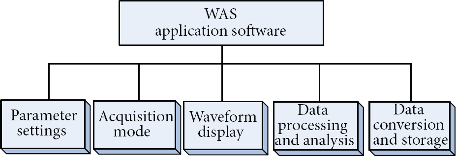
Architecture of the application software.
The parameter setting module sets the input signal type, input range, sensor sensitivity, bias, and other functions. The data processing and analysis block conducted modal analysis, power spectrum analysis, and Lissajous pattern analysis, and it also had access to a variety of statistical information, such as maximum, minimum, peak-to-peak, and RMS.
5. Performance of the SA-Based Wireless Monitoring System
5.1. Experimental Setup
The performance of the integrated wireless monitoring system was evaluated by the dynamic loading test. The test configuration is shown in Figure 5. The dynamic stress was applied on the SA by the servo-hydraulic test machine (MTS 810). The high-impendence charge signal was converted to the low-impendence voltage signal by a charge-to-voltage converter (HK9209, Hengke Tech. Co., China). The capacitance of the converter was set to 5000 nF. The converted voltage signals then were measured by the wireless system and the wired system in parallel (NI-4472 module, National Instruments). The sampling frequencies of both the wireless and wired system were all set to 100 Hz. The wired system also measured the load signal applied by the servo-hydraulic test machine. Figure 6 shows a photo of the test.
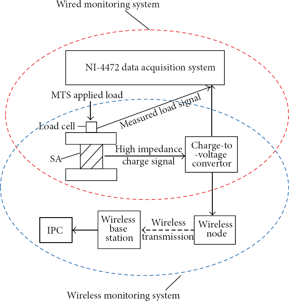
Configuration of the test system.
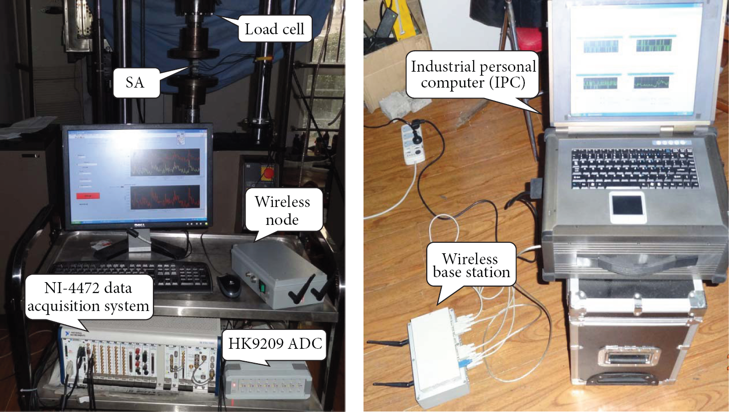
A photo of the test system to measure the dynamic excitation.
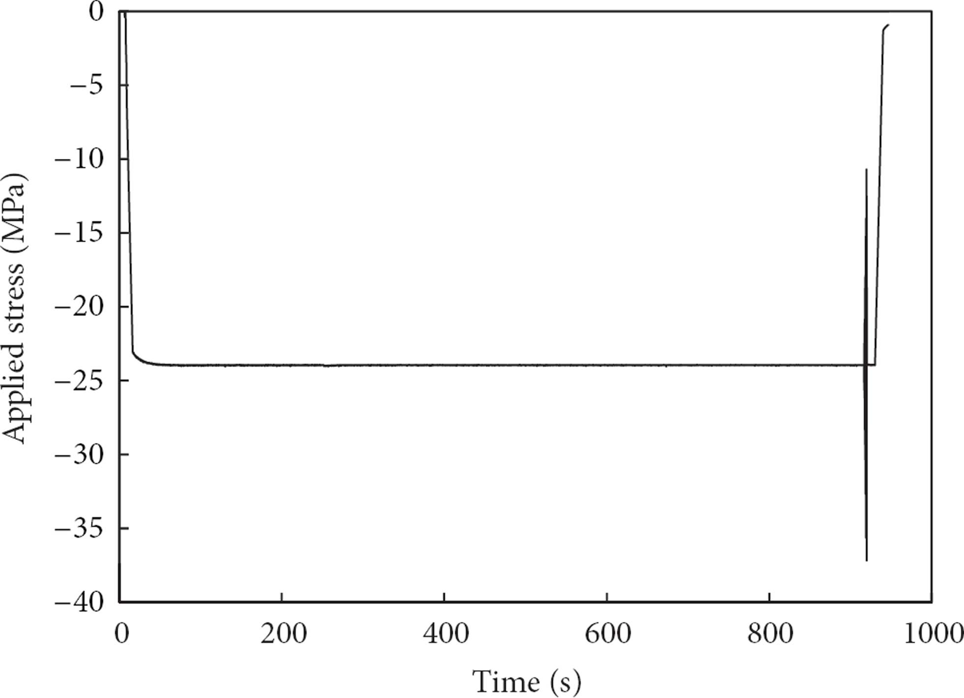
The loading scheme applied on the SA is shown in Figure 7. Firstly, a static compressive stress of 24 MPa was applied on the SA, which lasted for 15 minutes to allow the exhaustion of the depolarization process of the PZT material [18]. Then, a dynamic stress in a cosine wave form with a frequency of 3 Hz and stress range of 1.6–16 MPa was applied. The picked loading frequency was within the resonant frequency of general earthquake ground motions. The highest loading stress of about 40 MPa corresponded to the crushing strength of commonly used concrete. The test aimed to evaluate the performance of the wireless monitoring system in measuring the structure's response during full damage processes under strong earthquake ground motions.
Loading scheme.
The profile of the applied alternating stress and the SA output voltage measured by the wired and the wireless monitoring system are depicted in Figure 8. It can be seen that the two measurements are quite close and their waveforms are close to the applied stresses. This test indicates that the wireless system is able to accurately measure the full damage process of the concrete structures under strong earthquake ground motions.
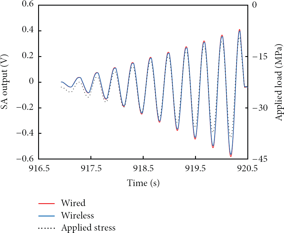
Applied stresses and the SA output voltage measured by the wireless and the wired monitoring systems.
5.2. Measurement of Tiny Random Excitation
When the static stress applied to the SA was maintained constant, tiny random vibrations still existed due to the perturbation of the servo-hydraulic system. The tiny variations of the output voltage from the SA were also measured by both the wired and the wireless monitoring system. These results allow us to evaluate the resolution of the integrated wireless monitoring system. The resolution of the system determines the weakest detectable response of the concrete structures resulting from minor earthquakes that are much more likely to occur than the strong earthquakes. Although it is unlikely that structural damage will occur during a minor earthquake, the structural response is still useful to improve human understanding of the structures global behaviors.
The results are compared as shown in Figure 9. It can be seen that the results of the two measurements are very close during 917 s to 920.5 s. The amplitude of the output voltage is 0.001 V, which corresponds to the stress of 0.04 MPa. This indicates that the wireless monitoring system has a high resolution and is capable of monitoring the response of the structure under minor earthquakes. The FFT results of these two measurements are also compared in Figure 10. It can be seen that the frequency components are distributed in the low-frequency range of 0–5 Hz, which is similar to that of the earthquake ground motions. The frequency spectra of these two measurements are almost the same, reconfirming that the integrated wireless monitoring system is also capable of seismic monitoring in terms of frequency response.

SA output measured by the wireless and wired monitoring system.

FFT results of the wired and wireless measurements in the frequency range of (a) 0–15 Hz and (b) 0–5 Hz.
6. Conclusions
The smart aggregate has been integrated with a charge-to-voltage converter, a microprocessing unit, a wireless transmission unit, a base station, and a host personal computer to form a wireless seismic monitoring system. The performance of the wireless monitoring system is evaluated through a dynamic loading test. The output voltage of the smart aggregate is measured by the wireless monitoring system and a wired monitoring system in parallel. The test results show that the SA-based wireless seismic monitoring is able to reliably measure the dynamic stress of up to 40 MPa with resolution of 0.04 MPa. This implies that it will measure both the full damage process of concrete structures under strong earthquake ground motions and the dynamic response under minor earthquakes. This study initiates the application of the SA-based wireless networks for full damage process monitoring of concrete structures under strong earthquake ground motion.
Footnotes
Acknowledgments
This paper received financial support (Grants 50908031, 51161120359, and 51108060) from the National Science Foundation of China and the Provincial Education Department of Liaoning Province (Grant no. L2013020).