
Abstract
The lifting and propulsion mechanism of a novel biped robot inspired by the basilisk lizard's water-walking function has been developed. The movement trajectories of the Watt-I planar linkage are brought out by combining the movement equations of the four-bar mechanism and the coordinate transformation equations, which are used to simulate the foot trajectories of the basilisk lizard, and the lifting and propulsion mechanism of the biped robot walking on water is carried out. The links' parameters are optimized by taking the trajectories overlap ratio as the objective function. The prototype of the biped robot walking on water is manufactured by the results of the kinematic analysis on the robot. And the lifting and propulsion force curve on the robot from water is measured. The experiment results show that the lifting and propulsion system can satisfy the function requirement of the biped robot walking on water.
1. Introduction
The requirement that the robot has the functions of walking on both land and water is brought out to implement the works such as military surveillance, water quality monitoring, wetland detection, search, and rescue in the complex environments. The technologies of the legged robot walking on the hard land surface are mature relatively [1, 2], so it has been the research hotspot in the robotics that study the mechanisms of legged robots walking on different kinds of material surface such as water and soft sand to expand its walk domain.
Song and Sitti have developed a robot with twelve legs which can walk on water by mimicking the water skipper [3]. The robot floats by the water surface tension and moves by driving the special paddle-type legs, so the payload of the robot is low (9.3 g), and its walk velocity is slow (3 cm/s). The robot will sink when the water-air interface which keeps its balance broken, which means that the robot cannot walk on the water surface with violent ups and downs, and its ability of resisting windstorm is weak.
Floyd and Sittihas developed a quadruped robot walking on water, which realizes the water-walking function by its four disk feet striking water [4]. The robot feet move with the constant angle, which leads to the bigger water resistance when they are lifted and reduces the robot's payload (50 g).
The basilisk lizard is capable of walking on water surface at the speed of about 1.5 m/s and at a stepping rate of 5–10 Hz (per leg). Compared with a ship, the lizard's move mode leads to the smaller volume under water and can reduce the water resistance, which can promote the propeller efficiency. And the biped water-walking mode has the following advantages.
The water resistance of the biped walking mode is smaller than the quadruped mode.
Just like the human walks on the soft sand surface, the biped water-walking mode can make the lizard body lean forward, which is useful to control the body's balance.
The biped water-walking mode can make the lizard head be higher and get a more wilder field of vision.
In this case, the water-walking ability is what our robot attempts to duplicate. This robot employs momentum transfer for both lifting and propulsion, instead of surface tension, which other water-walking robots adopt.
The work is helpful to expand the locomotion domain of biped robot. Further work in this field can lead to completely amphibious bipedal motion. Applications include exploration, and search, and rescue in partially flooded or marsh-like environments and of remote controlled toy models which can run anywhere. This work can also help increase the understanding of the basilisk lizard and its ability to walk on both land and water.
In this paper, we develop a novel biped water-walking robot inspired by basilisk lizards. Firstly, we emulate the water-walking function of the basilisk lizard by Watt-I planar linkage. Then the lifting and propulsion mechanism is developed, and the kinematics analysis of the mechanism is carried out to select the suitable body material and driver. To obtain the lizard's joints trajectories as more exact as possible, we optimize the links' parameters. At last we manufacture the biped robot prototype to test its lifting and propulsion ability.
2. Research on Dynamics Mechanism of Biped Robot Walking on Water
The biped robot walking on water is aim to the water-running function of basilisk lizards. The water-walking stride can be roughly divided into three phases: slap, stroke, and recovery. The forces experienced by the leg and foot are different in each phase and have differing effects on the lizard's ability to stay afloat. These phases are shown in Figure 1. The surface-tension effect on the water-walking ability is negligible. It can be known from Figure 2 that the joints trajectories on one leg of a lizard are in the same plane approximately.

Pictures of basilisk lizard walking on water.

Movement trajectories of basilisk lizard walking on water.
In this paper, we implement the water-walking function of the biped robot by simulating the sole trajectory of the lizard walking on water, so the robot's water-walking stride is also divided into three phases: slap, stroke, and recovery. In the slap and stroke phase, the lizard sole strokes downward, pushes against the water beneath its foot, and create an air cavity in the water. The momentum transfer from the lizard's foot to the water during this stroke phase generates the main lift force to stay afloat and the main propulsion force to thrust forward. From [5, 6], the force of lizard foot entering water is

where C D * ≈ 0.703 is the constant drag coefficient, ρ is the water density, g is the acceleration of gravity, S is the effective area, and h(t) is the time varying depth of the foot. This holds true over a large range of velocities for both lizards and experimental equipment. The force curve in a stride can be got according to the above equation, which is shown in Figure 3.

Force curve during robot walking on water in simulation environment.
3. Design of Lifting and Propulsion Mechanism
3.1. Kinematics Analysis of Double Bar Assur Group of Watt-I Linkage
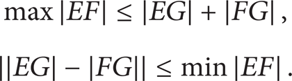
Watt-I linkage is shown in Figure 4, and the double bar Assur Group links the connecting link and the output link of the grounded four-bar linkage. The double bar Assur Group will not constrain the four-bar linkage as long as the following conditions are satisfied:

Watt-I planar linkage.
In Figure 4, the connecting links of AB, BC, CD, and AD constitute the grounded four-bar linkage, whose lengths are represented by l1, l2, l3, and l4, respectively. Suppose that the angles between the links AB, BC, and CD and the x-axis are φ1, φ2, and φ3, respectively, and the interior angles of ΔBCE and ΔDCF are θ i and φ i (i = 1,2, 3), respectively. The link AB is the driving link at the constant angular velocity of ω. So the angular displacements can be known as follows respectively [7]:
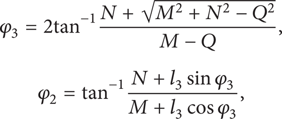
where M = l4 – l1cosφ1, N = – l1sinφ1,
So the trajectory of the point C can be got from (3):

The mechanism of ABCD is a quadrilateral, so

Supposing ∠ECF = φ5, its value can be deduced out from (5):

A new coordinate system x′Cy′ is built by setting the point C as the origin and the side CF as the x′-axis, so the angle between the x′-axis and the x-axis is got as
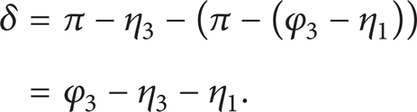
The links of CE, EG, GF, and CF constitute a four-bar linkage also, and the lengths are represented as s2, l5, l6, and k3, respectively. The link CE is looked as the driving link. Supposing that the angles between the rods EG and FG and the x′-axis are φ7 and φ6, respectively, the angular displacements can be known as

where H = k3 – s2cosφ5, J = – s2sinφ5, and
So the trajectory of the point G in the coordinate system x′Cy′ can be deduced out:

And the trajectory of the point G in the coordinate system xAy can be got according to the transformation formulas of the coordinates:
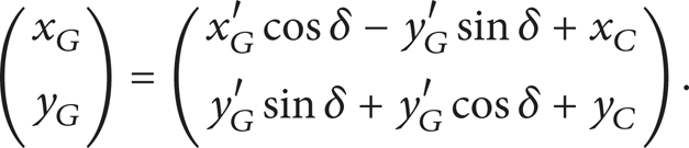
The trajectory of the point G is shown in Figure 4.
3.2. Virtual Prototype Design of Lifting and Propulsion Mechanism
The trajectory of the point G shown in Figure 4 is similar with the sole trajectory of the basilisk lizard shown in Figure 2, so we adopt the improved Watt-I mechanism as the lifting and propulsion mechanism for the biped robot.
We look on the point G as the center point of the robot's sole and move it to be under the x-axis to implement the stroke function of the lifting and propulsion mechanism. Simultaneously the triangle plates are replaced by the slender rods, so θ1 = π, η1 = 0, θ2 = θ3 = η2 = 0, η3 = π, and

Moreover, we rotate the rod AD an angle less than π/4 around point A to make the sole parallel to the water surface, then the lifting and propulsion force may be bigger. The final skeleton of the lifting and propulsion mechanism is shown in Figure 5.

Skeleton of lifting and propulsion mechanism.
It can be known from Figure 1 that the two feet slap the water surface alternately during the lizard walking on water. For mimicking the lizard walking on water, we design the same lifting and propulsion mechanisms for the both sides of the biped robot. The mechanisms are driven by a same motor, but their phase difference is π. The major structure of the biped robot is shown in Figure 6.

Major structure of robot.
In Figure 6, the driving system is composed of a motor and a reducer fixed on the main frame, and the transmission agent includes a bevel gear pair and a transmission shaft. The bevel gear pair turns the driving motion perpendicular to the rotational motion around the shaft, and the driving torque is passed to the two lifting and propulsion mechanisms. A balance apparatus is fitted on the after body of the robot's frame, which can keep the robot being balance when it is walking on water.
3.3. Optimization of Lifting and Propulsion Mechanism
To imitate the water-walking function of the lizard perfectly, the trajectory of point G should fit the points on the given trajectory as more as possible. The given trajectory parameters during the lizard slap and stroke phases are shown in Table 1.
Parameters of given trajectory. Unit: mm.

The optimized objective function for reappearing the trajectory is built as follows according to minimizing the deviation between the points of the actual trajectory and the given:
where
There are two constraint conditions for the four-bar linkage ABCD shown in Figure 4: (1) the constraint condition of crank existence in a four-bar linkage and (2) the constraint condition of the transmission angle [ζ]. We set [ζ min ] ≥ 25° and [ζ max ] = 180° – [ζ min ], so the constraint conditions can be written as

where

Moreover, it can be known from Figure 2 that the double bar Assur Group should satisfy the following conditions to keep the mechanism working steadily.
When the stability margin is 20°, the condition of the mechanism working without a singular point should be

The condition of the sole slapping the water surface effectively to produce the lifting and the propulsion force should be

For minimizing the deviation between the points of the actual trajectory and the given, we set (12) as the objective function, (3), (8), and (10) as the variable functions, and (13)~(16) as the constraint conditions. The optimum values of the design variables can be got as follows by taking the penalty function method: AB = 24.53 mm, CF = 12.69 mm, DF = 35.58 mm, BC = 38.64 mm, BE = 39.31 mm, FG = 114.64 mm, EG = 54.06 mm, AD = 49.76 mm, and δ = 42.83°.
The comparison between the parameters of the optimization trajectory and the given trajectory is shown in Figure 7.

Comparison between parameters of optimization trajectory and given trajectory.
4. Kinematics Analysis on Robot
The velocities of the links CD and BD can be deduced out based on the kinematics principle of a four-bar mechanism, which are as follows:

And the angular accelerations of the links CD and BC are, respectively,

The angular velocity and acceleration of φ5 can be worked out from (11), and they are, respectively,
In the same way, the angular velocity and acceleration of δ are, respectively,

According to the kinematics principle of a four-bar mechanism, the angular velocities of the links GF and EG in the coordinate system x′Cy′ are known as

and the values of their angular acceleration in the coordinate system x′Cy′ are

Then the angular velocities and accelerations of the links GF and EG can be got from (20)~(22):
5. Manufacture of Prototype and Experiments
5.1. Design of Control System
The ZMP criterion is adopted by most of the biped robot walking on land to keep balance. But when a robot is walking on water, the air caves will come into being, and the disturbances of current rush and splash are more complex than on land. So a new control method is necessary to the biped robot walking on water.
It is necessary to reduce the foot slapping frequency properly to enhance the robot stability when it is disturbed. Therefore, the CPG-fuzzy control algorithm of the biped robot walking on water is proposed for achieving sufficient balance control and gait switching [8]. The CPG-fuzzy control system (Figure 8) of the robot is designed by using the CPG controller and the fuzzy control rules.

CPG-fuzzy control system of biped robot.
5.2. Manufacture of Prototype
In consideration of the functional requirements of the robot walking on water, the main frame, the lifting, and propulsion mechanisms should be made from the light material, and their intensity should be high enough to deform slightly under the action of the reaction force. So they should to be made from aluminum alloy LY12. The driver group MAXON 221011+134161 is adopted as the driving system of the biped robot. The rated power of the group is 5 w, and its rated torque is 0.15 Nm. We choose flexible rubber as the material of the robot soles. The prototype of the biped robot walking on water is shown in Figure 9, and its whole weight is 3.2 N.
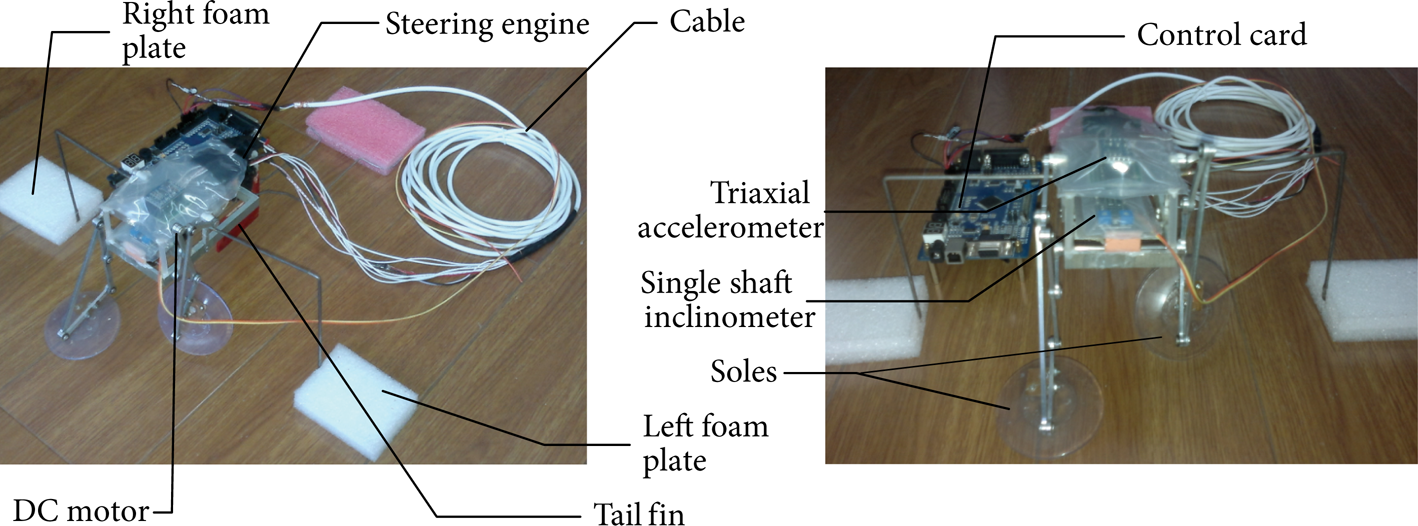
Prototype of biped robot walking on water.
5.3. Experiments
The volumes of the left foam plate and the right one are 91.605 cm3 and 97.712 cm3, respectively, and the total buoyancy of the two foam plates is 1.856 N when they are all under water. The buoyancy is less than its gravity, so the robot will sink when it is placed on the water statically, and the sequence diagrams of the robot sinking are shown in Figure 10.

Sequence diagrams of robot out of work sinking.
The sequence diagrams of the robot walking on water are shown in Figure 11. The robot can walk on water due to the lifting and propulsion force produced by the legs slapping from 1 s to 4 s. As soon as the power supply is cut off when the time is 4 s, the robot will stop slapping and begin to sink in water. At last the robot will sink totally when the time is 6 s.

Sequence diagrams of robot walking on water.
It can be known from Figures 10 and 11 that the lifting and propulsion force is the main factor to keep the robot away from sinking.
5.4. Measurement of Lifting and Propulsion Force
The lifting and propulsion force is the decisive factor of the robot's load capacity; that is, if the force is larger, its load capacity will be stronger. We build an experimental platform shown in Figure 12 to test the lifting and propulsion force of the robot. We mount the strain gages on both soles (Figure 13), and the voltage variation curve of one gage is shown by an oscilloscope, from which the lifting and propulsion force can be got. And the curve of the lifting and propulsion force is shown in Figure 14.

Experimental platform.

Sketch map for mounting strain gauges.

Force curve measured by strain gauge.
The force curve of Figure 14 is similar to the curve in the simulation environment shown in Figure 3.
The peak value of the lifting and propulsion force in Figure 14 is 2.6 N, which is less than the force value of 4 N in the simulation environment. And the valley value of the force in Figure 14 is about 0.8 N, which is less than the value in Figure 3 of 1.3 N also. The simulation force values are bigger than the realistic ones because the transmission efficiency, the pressure of the atmosphere, and the deformation of the soles are not considered in the simulating process.
6. Conclusions
Inspired by basilisk lizards, a novel biped robot running on water has been designed in this paper, which will offer theoretical and design basis for developing the bionic amphibious biped robot. The virtual prototype of the robot is built by designing the propulsion mechanism with Watt-I planar linkage. At last the prototype of the robot has been made and the water-running experiments have been done. The lifting and propulsion force generated by the propulsion mechanism is about 1.3 N.
While there is still significant work remaining. The motion control method of the amphibious biped mechanism should be studied to implement the control method of the robot motion mode such as going straight, turning, and avoiding obstacle. The composite propulsion mechanism of the amphibious biped robot should be designed, and the propulsion movement on land and water should be implemented by using the different modes of motion and control of the mechanism.
Footnotes
Acknowledgments
This work is supported by the National Natural Science Foundation of China (no. 50905175) and the National Program on Key Basic Research Project of China (no. 2011CB302106).