
Abstract
In order to improve the modeling efficiency and realize the deformation simulation of helix twisting structure, a computer-aided design system based on mass-spring model is developed. The geometry structure of helix twisting structure is presented and mass-spring model is applied in the deformation simulation. Moreover, the key technologies such as coordinate mapping, system render and system architecture are elaborated. Finally, a prototype system is developed with Visual C++ and OpenGL, and the proposed system is proved efficient through a comparison experiment.
1. Introduction
Due to the characteristics of light mass, high tensile rigidity, and compact structure space, helix twisting structure (HTS) has been widely used in engineering fields such as mine hoists field, port loading, and unloading field [1–3]. The parametric model plays an important role in the design and analysis system of HTS, and a quick modeling approach for helix twisting structure is a challenging issue and has received increasing interest among researchers in recent years [4–6].
At present, researchers from home and abroad have worked on the modeling approaches for HTS and proposed several solutions. An analytical model for helically wrapped wires in a cable subjected to tension and small bending was presented. With this geometry, an approximate upper limit of the cable curvature could be obtained [7]. A more realistic analysis model determination of an independent wire rope core which was defined with the parametric equations of the nested helical geometry was proposed and the model with finite element analysis was analyzed as well [8]. A precise mathematical model and an approximate mathematical model for the calculation of twist angle and the diameter of strands formed of an arbitrary number of wires were presented and the responding application software was developed [9]. The mathematic model of simple twisting structure was proposed and the force analysis was presented [10]. Moreover, some specific categories of ropes, such as triangular strand rope and seal type rope, were also researched and the modeling methods by using Pro/E were proposed [11–13].
In fact, HTS should be a flexible object and can be carried out for the defamation simulation [14–18]. Thus, flexible modeling approaches for HTS are becoming more important and there are two main deformable models for deformation simulation: finite element model (FEM) and mass-spring model [19–21]. FEM has the absolutely advantage in physical accuracy over mass-spring model; on the contrary, mass-spring model is more efficient when applied to real-time simulation. Nowadays, researchers have worked on the problem and proposed several models. To achieve the realistic simulation of tissue cutting, an improved mass-spring model was proposed and a classic algorithm was designed [22]. The application of controller synthesis to 3D mass-spring lattices that were subjected to nonholonomic constraint was described. In contrast to the generation of motion controllers for 3D articulated linkages, comparable controllers for mass-spring lattices were computed in tens of minutes not tens of hours [23]. To study the dynamics and the vibrational behaviors of protein, a mechanical mass-spring model represented by point masses and harmonic spring was applied to bimolecular structure, which was good at in reducing computational cost and maintaining the accurate predictions [24]. However, there are some largely open problems in haptic simulation and rendering such as contact force and deformation modeling for haptic simulation of a discrete globe mass-spring model, especially for global deformation. In order to solve these problems, the theory of virtual work was used, and the relations between the virtual force and nodal displacements were analyzed to obtain elastic deformations. Thus, the global deformation was controlled by the total nodal deformations based on a force equation at each node [25]. A mass-spring model with pressure based method was presented to realize the deformation simulation of corona with good fidelity and real-time nature [26].
However, although many approaches for helix twisting structure modeling have been proposed in the above literature, they have some common disadvantages summarized as follows. Firstly, the modeling time is vast and modeling process is complex through the universal platform such as Pro/E, UG and Inventor VBA, and so forth. Secondly, the usual modeling approaches are not based on the rigorous mathematical foundation of HTS. Finally, almost all researches take HTS as rigid body and few researches have focused on the modeling approach for HTS as a flexible object. In this paper, mass-spring model is applied in the modeling of HTS and a computer-aided design system is developed to tackle these problems.
Bearing the above observation in mind, we apply a novel approach based on mass-spring model to the problem of helix twisting structure modeling and develop a computer-aided design system for HTS, and the rest of this paper is organized as follows. In Section 2, the geometry structure of HTS is put forward. In Section 3, mass-spring model is applied to the deformation simulation of HTS. In Section 4, key technologies of the proposed system are elaborated. Section 5 develops a prototype system based on the above-mentioned key technologies and a comparison experiment is carried out. The conclusions and future work are summarized in Section 6.
2. Geometry Structure of Helix Twisting Structure
As shown in Figure 1, HTS is composed of helix strands which are distributed over different layers. The helix strands can be expressed through the strand centerline and strand radius. For a layer, there is a primary helix strand and other helix strands can be calculated based on the primary helix strand.

Geometry structure of helix twisting structure. P jki (x, y, z): j is the index of a layer, k is the index of a strand in each layer, and i is the index of a point along the helix strand centerline.
For a primary helix strand, the index k is equal 0 and the points on the centerline of primary helix strand can be described as follows:

where R j is the radius of the jth layer, φ ji is the angle increment around Z axis, α j is the helix angle of the jth layer, and n is the number of layers.
The points on the other helix strand centerlines can be calculated by a rotation transform based on the primary helix strand and the formula can be described as follows:
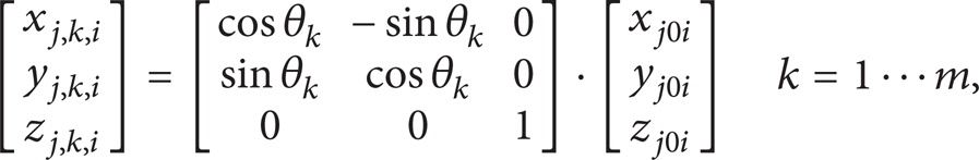
where m is the number of helix strands in a layer and θ
k
is the rotation angle around Z axis, which can be easily calculated by

In order to simplify calculating, we assume that the helix strands are contacted with each other and the radiuses of helix strands in the same layer are equal in numeric value. Thus, the radius of jth layer can be calculated as follows:

where the parameter of r0 is the radius of center independent strand.
After derivation of (3), the points on the cross-section of kth helix strand in jth layer can be described as follows:

where
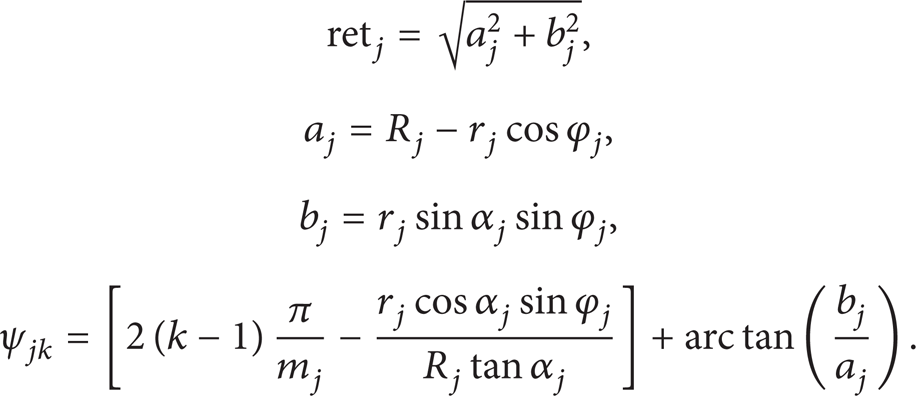
Thus, the radius of the jth layer can be calculated as follows:

3. Mass-Spring Model for Helix Twisting Structure
Compared with finite element model (FEM), mass-spring model has an important advantage in computational efficiency and usually used in real-time simulation such as the deformation simulation of soft tissue [27].
In order to illustrate the application of mass-spring model for helix twisting structure, we take a helix strand for example, as shown in Figure 2. Firstly, the helix strand is divided into several same segments. Secondly, mass points are selected from the circle of segments. Finally, springs and dampers are added, and the mass-spring model for helix twisting structure is established.

Mass-spring model of a helix strand.
In this paper, three different types of springs are applied in the deformation simulation of HTS under extra load, as shown in Figure 3. Structure spring is used for the structure connection, shear spring is used for avoiding from twisting, and flexion spring is used for making it smoothly.

The mass-spring model for helix strand structure.
For a mass point, the kinematics differential equation can be described as follows:

where F
i
is the external force on the mass point, K
ij
is the spring stiffness between mass point i and mass point j. D
ij
stands for damping coefficient between the mass point i, and j,
Nowadays, many approaches have been proposed to solve the mass of mass point. This paper treats mass point as a mass lumping [28] and the tetrahedron mass-spring model for HTS can be shown in Figure 4.

The tetrahedron mass-spring model for HTS.
As introduced above, the model of a single HTS, as shown in Figure 4(a), can be divided into several segments, and for a segment, the model can be expressed as a polyhedron. To be convenient for explanation, the single one can be expressed as a cuboid, as shown in Figure 4(b). In Figure 4, the current mass point is M i , and the red line is a shared line among all tetrahedrons surrounding the mass point M i . Assume that the material density ρ is a constant, thus, the mass of mass point i can be calculated by M i = ρ · V i , where V i is Voronoi volume and depends on the surrounding volume of mass point i. The mass of mass point i can be calculated as follows:

where Φ i is a set of tetrahedrons which are associated with the mass point i. Ω k is a set of points in the current tetrahedron k. V(i, Ω k ) is the volume of current tetrahedron k which can be descripted as follows:

where p i is the position of current mass point i, d(p, p i ) is the Euclidean distance between mass point p and p i , and d(p, p j ) is the Euclidean distance between mass point p and p j .
In practical, the majority of materials are nonlinear, nonhomogeneous, anisotropic, and viscoelastic. As a simplified method, we assume that the material is linear, elastic, homogeneous, and isotropic. As proposed in [29], the spring stiffness K ij is proportional to Young's modulus and the length of shared edge connected with mass point i and mass point j. In order to compute shared edge length, a fictitious length is proposed and the final stiffness can be calculated as follows:

where E is the Young's modulus.
For dampers stiffness, we refer to [30, 31], which is the sum of mass and stiffness with different weight and the formula can be expressed as follows:

where α1 and α2 are the weights of mass and stiffness, respectively, and both of them are predefined constants. Actually, although the two parameters have been presented in many papers, it is not easy to get the accurate values. In this paper, two empirical values are applied in the simulation example.
4. Key Technologies of the Proposed System
4.1. Coordinate Mapping
It is a vital task to confirm the position of mass points for the modeling of mass-spring model [32, 33]. Actually, a mass point in Cartesian coordinate can be represented as (x, y, z, index(k)). In order to add the spring and simplify the computation process, plane coordinate is applied and a coordinate mapping approach is proposed as shown in Figure 5. In plane coordinate, a mass point can be represented as

Coordinate mapping.
The flowchart of coordinate mapping can be shown in Figure 6. To get the mapped coordinate (x, y, z, index(i, j)), the array size (u + 1) × v is given firstly and then all the matters are conducted in two loops. Thus, the (x, y, z, index k ) is converted to plane coordinate with double index.
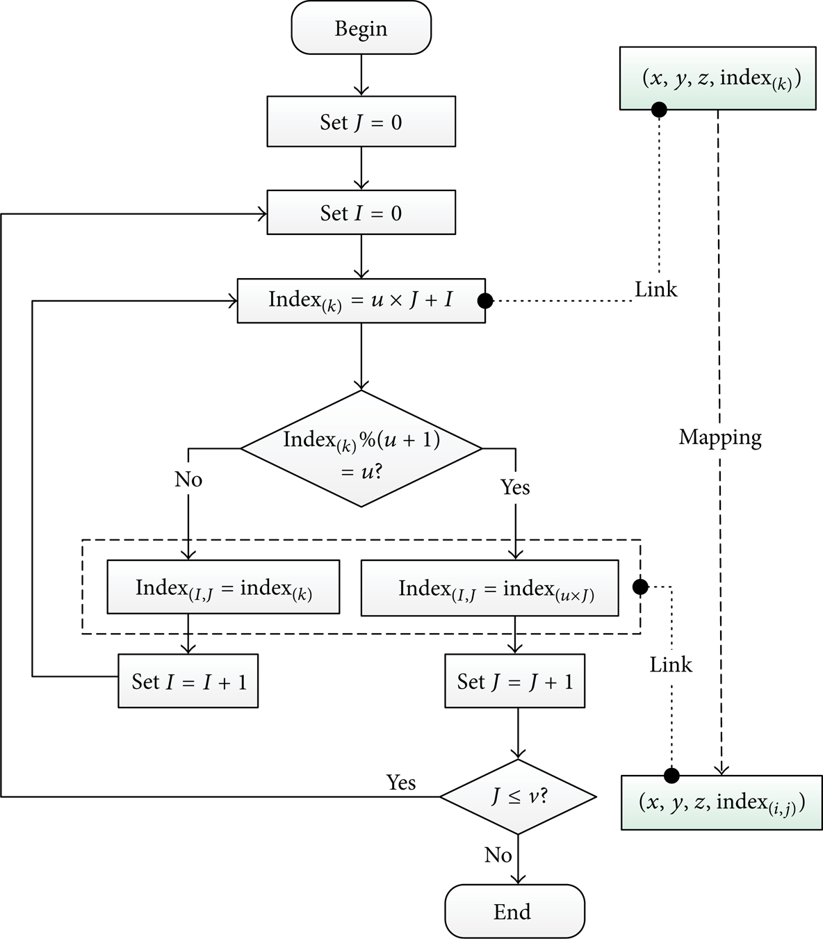
The flowchart of coordinate mapping.
4.2. System Render
The performance of system render decides whether a computer-aided design system can be applied in a real-time simulation environment. Multistage nested display list of OpenGL, the integration of mesh nodes, and mass points are designed to improve the performance of system render, and the procedure of system render is shown in Figure 7.

The procedure of system render.
The procedure of system render is composed of three steps: system setting, calculation and storage, and render. System setting such as background color setting, model color setting and coordinate system setting should be finished firstly. Secondly, the position of mesh nodes is initialized and the displacement of mass points is calculated through the integration of mass-spring model and coordinate mapping. Finally, helix twisting structure and the scene are rendered. Moreover, the steps of calculation & storage and render will be carried out once more if the parameters are modified.
4.3. System Architecture
In order to realize platform-independent of the computer-aided design system for helix twisting structure, the four-tier system architecture is designed as shown in Figure 8. In this architecture, the upper tier can transfer the function modules of the nether tier and the definition of every tier can be described as follows.

The system architecture.
Environment tier plays an import role in the computer-aided design system for helix twisting structure. As a kind of most-derived graphic library for 3D graphic development, OpenGL can be used to render 3D models perfectly through the extremely powerful API functions [34].
Business tier is the central part of the computer-aided design system for helix twisting structure. It is composed of several tools and models that provide data services and graph services to carry out the calculation, extrusion, and render tasks.
OpenGL view is an encapsulation of the business tier and the basic function modules of the computer-aided design system for helix twisting structure can be provided such as real-time simulation and deformation simulation, and so forth.
User interface tier is an interface for users to access our system.
5. Prototype System and Discussion
5.1. Prototype System
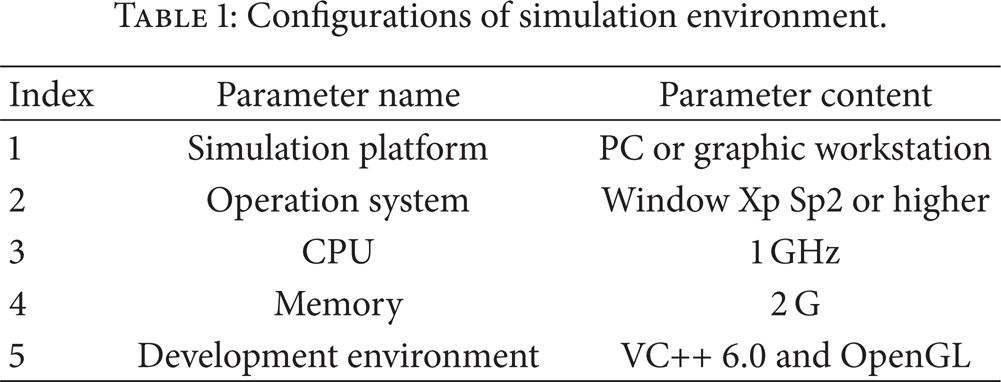
Based on the above technologies, a prototype system named after HTS Designer has been developed with Visual C++ and OpenGL, and the configurations of simulation environment are shown in Table 1.
Configurations of simulation environment.
In our system, a 3D model for HTS can be modeling quickly and exactly through the input of several parameters such as period, helix angle, strand radius, and layer number, as shown in Figure 9(a). Besides circle cross-section, HTS with triangle cross-section can also be modeled, as shown in Figure 9(b). Moreover, deformation simulation of HTS based on mass-spring model can be carried out with or without collision detection, as shown in Figures 9(c) and 9(d).

Interface of the prototype system.
The proposed approach has been applied in some industrial application examples such as elevator simulation and crane simulation as shown in Figure 10.

Industrial application examples of proposed approach.
5.2. Discussion
In order to prove the outperforming others of the proposed system, a comparison experiment between HTS Designer and Inventor VBA is carried out. The configurations of simulation environment for two systems are uniform. In order to avoid the random error, each system is run 100 times and calculates the average values. The average run time of two systems for 1 layer HTS, 2 layers HTS and 3 layers HTS are shown in Figure 11.

Run time on HTS Designer and Inventor VBA.
It is observed that the performance of HTS Designer is better than Inventor VBA. With the number of layers increasing, the gap between two systems is growing ever wider, and the outperforming others of the proposed system can be verified.
Using the multistage nested display list of OpenGL, HTS Designer can reduce the render time for some particular structures. Moreover, HTS Designer is just developed for helix twisting structure modeling and simulation, but Inventor VBA is capable of more event response, scene view render and part tree view refresh which exactly influences the run efficiency.
6. Conclusions and Future Work
This paper develops a computer-aided design system to improve the modeling efficiency and realize the deformation simulation of helix twisting structure. The geometry structure of HTS is presented and the mass-spring model for HTS is proposed. The flowchart of coordinate mapping and the procedure of system render are designed. Moreover, the system architecture is provided and a prototype system is developed. In our system, helix twisting structure with different layers and cross-sections can be modeling quickly and exactly, and deformation simulation of HTS based on mass-spring model can be carried out with or without collision detection. Comparison results show that the proposed system is efficient.
Future work will mainly focus on the optimization of HTS Designer, including improving the system robustness, enriching the categories of HTS, and enhancing the interactive operation.
Footnotes
Acknowledgments
The support of National High Technology Research and Development Program of China (no. 2013AA06A411), National Natural Science Foundation of China (No. 51005231, 51005233), Qing Lan Project of Jiangsu Province, and the Priority Academic Program Development of Jiangsu Higher Education Institutions in carrying out this research is gratefully acknowledged.