
Abstract
Polarization reconfigurable microstrip patch antenna is presented for 2.4–2.5 GHz wireless sensor network and WLAN applications. Dual feed degenerate mode patch is used as the starting point for circular polarization and L-shaped islands which can be connected or disconnected to the main patch via RF switches are placed around the patch. When L-shape structure is connected, the patch radiates in linear polarization modes with either vertical or horizontal polarization depending on the feed being used. When RF switches are not biased, the antenna is in circular polarization mode. Full wave simulations and measurements were carried out to validate the design.
1. Introduction
Polarization reconfigurable antennas are becoming increasingly popular due to ever increasing wireless applications, especially at 2.4 GHz ISM band. Different polarizations on the same antenna offer key advantages in multipath fading environments and provide means for multiple-input multiple-output (MIMO) systems. Although polarization agile antenna concept has been around for quite some time [1], switching complexities and symmetry in radiation patterns still present challenges in the design.
The simplest method to achieve multipolarization is to switch perturbation segments of the antenna in an effort to change the antenna's electrical characteristics [2–16]. Usually, PIN diodes or RF MEMS was utilized as switch. Changing circular polarization states of a circularly polarized microstrip antenna can be achieved by employing two separate feeds (one for each polarization) and by simply switching the feeds. However, linear polarization states, in that configuration, would require a hybrid coupler and another set of RF switches, which was not practical. Another drawback of this configuration is to use multiple switches on the feed line which increases the noise figure of the system by at least the insertion loss of the switches used. Among slot coupled or slot reconfigurable shaped antennas, U-shaped slot antenna was studied for multiple polarizations [17–19]. However, symmetry in beam and electrical characteristics was relatively poor. Another extensively studied reconfigurable antenna shape was E-shaped antenna [3]. These antennas were proposed as wideband polarization agile structures. However, the size of the antenna was much larger than their resonant mode counterparts, and achieving four polarizations was problematic. For instance, in [3], linear polarization in only one state was achieved, and the frequency band was divided into two segments to cover the entire ISM band which makes the antenna impractical for many wireless applications. Varactor diodes loaded antennas were also proposed for frequency agile antennas [20–23]. Limited bandwidth and complex voltage biasing circuitry are prominent limitations of these antennas.
In our study, we took a well-known degenerate mode microstrip patch antenna for circular polarization states and loaded this structure with L-shape parasitic units which could be connected to the degenerate mode by RF switches. When parasitic unit is connected to the main patch, the antenna operates in linear polarization mode. Depending on which feed point is selected, either one of the linear polarization states can be invoked. We also employed chip inductors as RF choke instead of quarter-wave match sections which inevitably distort radiation pattern. Simulation and measurements indicate all four polarizations using only two RF switches.
2. Reconfigurable Microstrip Antenna
The antenna structure is shown in Figure 1. It is composed of degenerate mode square patch with corners cut and L-shape parasitic elements around the cut corners. RF switches are placed on cut corners to the center of L-shape element. When diodes are OFF, L-shape structure acts parasitic to the main antenna, and when diodes are ON, it is strongly coupled to the main patch. The distance between the parasitic element and the degenerate patch is critical to obtain proper circular and linear polarizations. Feed points determine the sense of polarization, that is, right hand or left hand circular, when diodes are OFF. Likewise, when diodes are ON, vertical or horizontal polarization can be obtained from the feed port. Polarization states for the switch positions and feed ports are summarized in Table 1.
Switch states and polarizations.


Reconfigurable antenna structure.
Layout of the biasing circuitry is very important and often the cause for asymmetry in radiation patterns. Quarter wavelength chokes have been implemented in past designs, but we observed that it distorted (even slightly tilt) the main radiation pattern. Hence, we used RF chip inductors as RF chokes. The ground return for the RF choke is implemented via small DC cable around the patch as opposed to via, although it's been simulated with via. In that sense, our design is different than earlier reconfigurable designs. The DC current through the diode is limited from DC supply with a series resistor.
Current distributions on the patch antenna when it is fed from port 1 or port 2 are shown in Figures 2 and 3, respectively. The symmetry in current distributions is mainly due to preserved symmetry in the antenna design. When diodes are ON, the current distribution on L-shape is stronger and enforces the current distribution on the main patch for linear polarization; that is, 90° phase shift between the alternate corners is not observed.

Current distribution on the patch (port 1 is fed, and port 2 is loaded with 50 Ω), (a) when diodes are ON and the (b) when diodes are OFF.
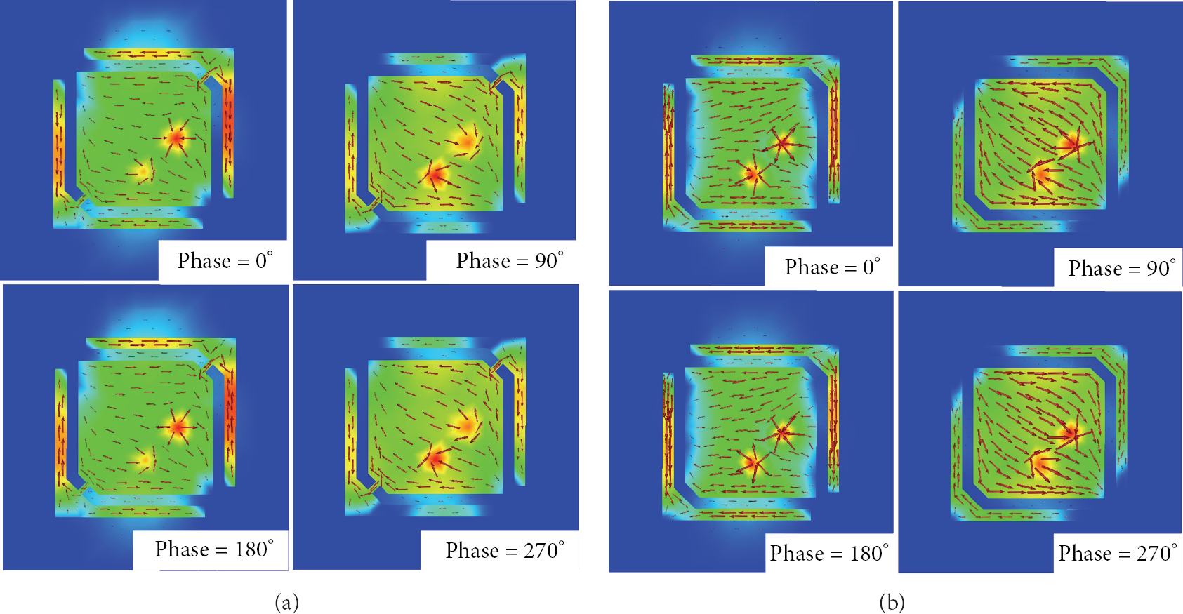
Current Distribution on the patch (port 2 is fed, and port 1 is loaded with 50 Ω), (a) when diodes are ON and (b) when diodes are OFF.
3. Simulations and Measurements of the Reconfigurable Antenna
Simulations of the antenna are carried out in FEKO, 3D electromagnetics solver. For realization, we used a substrate from Taconic RF65 (

Prototype of the reconfigurable antenna.
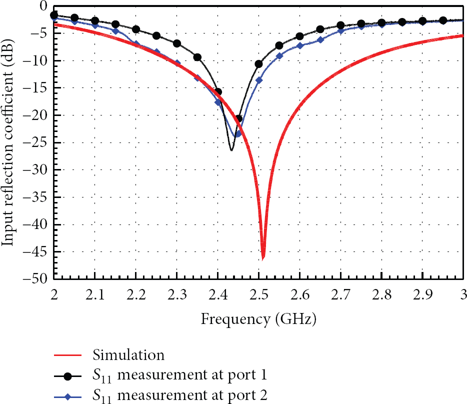
Measured and simulated input reflection coefficients when diodes are OFF.

Measured and simulated input reflection coefficient when diodes are ON.
Although measurements exhibit slight shift in frequency, the match is under −10 dB throughout 2.4–2.5 GHz.
The reconfigurable antenna gains are shown in Figures 7 and 8. They well match with those of standalone patch antenna modes. Cross-polarization levels could be further improved with slight modifications in the L-shape island geometry.
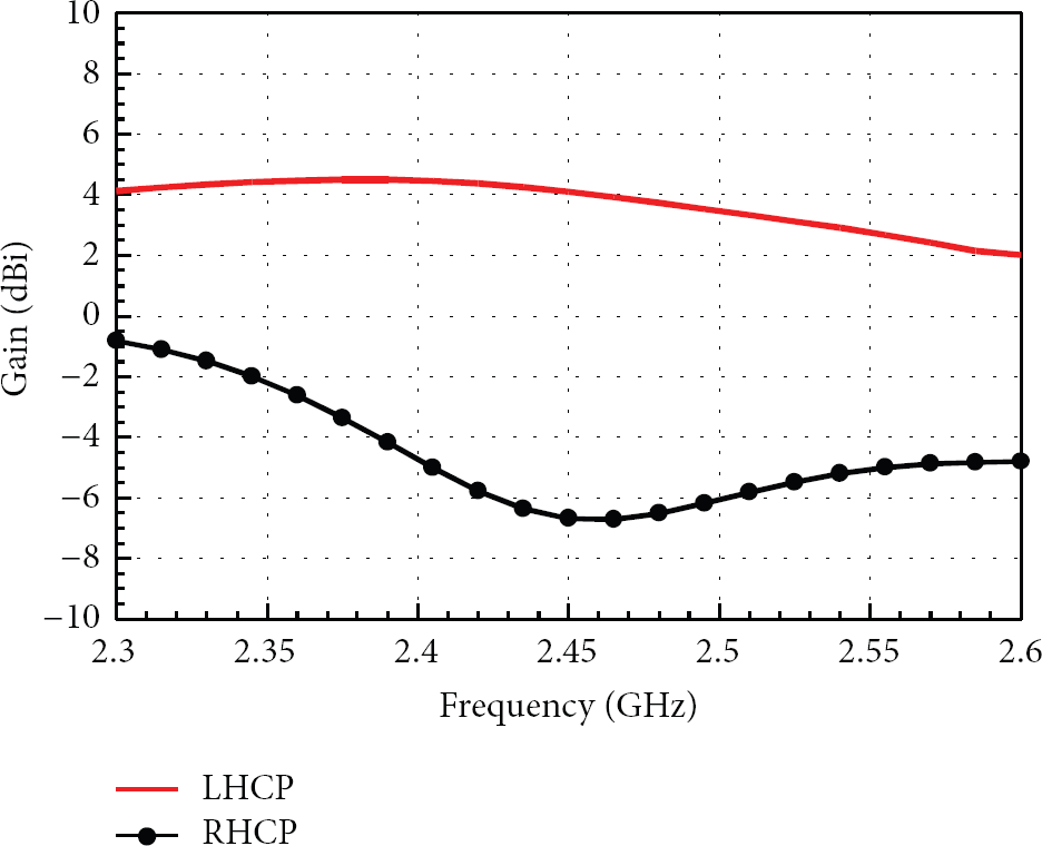
Antenna gain when diodes are OFF.
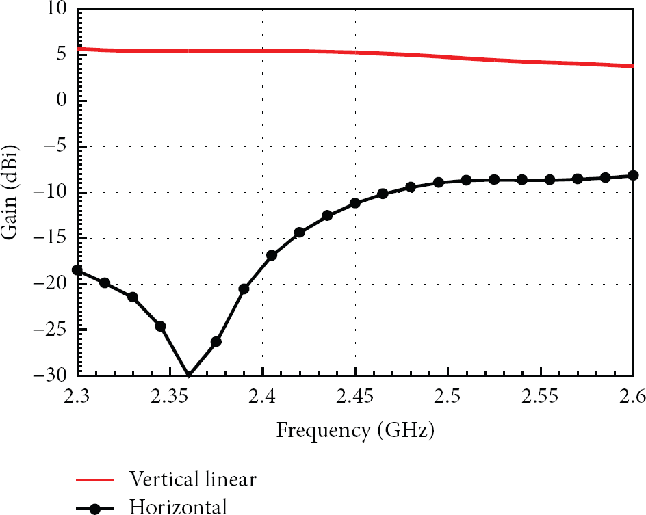
Antenna gain when diodes are ON.
Radiation patterns of the reconfigurable antenna fed from port 1 are illustrated in Figure 9. There is no beam asymmetry or tilt in the patterns due to symmetry in feed structure.

Gain patterns of the antenna at 2.45 GHz.
4. Conclusions
A reconfigurable microstrip patch antenna design for WSN applications has been presented. The biasing of the diodes and isolation of RF from DC path are achieved using discrete SMD components. The structure preserves its symmetry for circular and linear polarization modes. All the four polarizations can be achieved by simply switching the feeds and the diodes on the top metallic part. Antenna gain of the reconfigurable antenna is very comparable to its standalone degenerate mode patch for circular polarization and single mode for linear polarization counterparts. The proposed configuration is simple and easy to implement for polarization diversity antennas.
Footnotes
Acknowledgment
The authors thank EMSS FEKO, GmbH, Germany, for providing extended software license.