
Abstract
With regard to the reactor coolant pump and high flow-rate circulating pump, the requirements on the compactness of the structure, safety, and hydraulic performance are particularly important. Thus, the mixed-flow pump with cylindrical casing is adopted in some occasions. Due to the different characteristics between the special cylindrical casing and the common pump casing, the influence of the special casing on a mixed-flow pump characteristics was numerically investigated to obtain better performance and flow structure in the casing. The results show that the models with cylindrical casing have much worse head and efficiency characteristics than the experimental model, and this is caused by the flow in the pump casing. By moving the guide vanes half inside the pump casing, the efficiency gets improved while the low pressure zone at the corner of outlet pipe and pump casing disappeared. When the length of pump casing increases from the size equal to the diameter of outlet pipe to that larger than it, the efficiency drops obviously and the flow field in the outlet pipe improved without curved flow. In addition, the length of the pump casing has greater impacts on the pump performance than the radius of it.
1. Introduction
In order to get a compact structure, easy to install, and of high security and reliability characteristics, the cylindrical casing is applied in the reactor coolant pump and some high flow-rate circulation pumps. Such kind adopted structure of pump casing would affect the pump characteristics. Thus, it is an important design task to accurately assess its impacts on the performance and therefore the most appropriate structure can be obtained. For example, in the reactor coolant pump, the pump casing was mostly designed in spherical or cylindrical shape with different section profile while the impeller and diffuser were assembled inside. This structure feature would result in low pump efficiency, and thus a few researches were carried out to investigate its performance aiming at improving it later [1, 2]. Besides, for some high flow-rate circulating pump, in order to meet the requirements of the structure compactness, the flow channels were designed to be with a sharp turn where unstable flow and additional flow loss might be induced. Up to now, many scholars devoted themselves to finding a way to improve the pump hydraulic performance, such as by improving the impeller profile, the guide vane profile, or the inlet structure [3–7]. Ling Zhou et al. [3] and Shojaeefard et al. [4] numerically and experimentally investigated the effects of several key parameters of blades on the performance of a centrifugal pump, such as blade outlet angle and passage width. The results showed that the impeller outlet width had remarkable effect on the pump efficiency, and an optimal blade profile was finally obtained. J. H. Kim and K. Y. Kim [5] and Goel et al. [6] performed an optimization design studies on the influence of the vane shape on the hydrodynamic performance of a mixed-flow pump, taking the efficiency and the pump head as the objective function for optimization, respectively. The performance with optimal shape of vane yielded a 9.75% efficiency increase and an 8% pump head increase, respectively, compared to the reference design. van Esch [7] carried out experimental study on the effect of a nonuniform inflow velocity profile on the global performance of a mixed-flow pump. The results showed that the head, torque, and axial force was reduced by a few percent due to the nonuniformity. In addition, there were also many researches about improving the characteristics on the impeller-diffuser interaction [8–10] and the casing-diffuser/impeller interaction [11, 12] which would cause the pressure fluctuation and consequently the pump performance was influenced.
The pump casing was of equal important influence on the performance as a key flow component. Particularly in the volute pump, due to the asymmetric shape of the volute, pressure fluctuation and radial force would be produced and the performance of the pump would be affected [13, 14]. Many scholars made some researches on the way to optimize the flow field and the performance of the pump, such as by improving the volute tongue position [15–17], the radial clearance between the impeller outlet and the volute tongue [15], the type of the volute casing [18, 19], and the shape of cross-section [20, 21]. Wong et al. [15] conducted numerical investigations on the effect of radial gap and volute tongue position on the radial force and pressure head of the pump. The results showed that the pump with a radial clearance of 10% or the tongue position at 15 degrees presented a reasonably high pump head with a small radial force. Kim et al. [18] analyzed the radial thrust and the hydraulic characteristics variation in three types of volute casing numerically, such as the conventional volute casing, the volute with diffuser, and the double volute. The results showed that the hydraulic efficiency of single volute was higher than those of the other types about 2.5%. And the radial force of the volute with diffuser was smaller than the other types. Ji and Wang [21] found the shape of the volute cross sections and the volute tongue were the most important factors for optimizing the volute performance, but the effect was limited.
As mentioned above, the volute was mostly designed in spiral shape for the centrifugal pump. However, in the reactor coolant pump, the pump casing is designed to be cylindrical or spherical instead of spiral volute for the sake of design strength and inspection with the impeller and diffusers assembled inside while such kind structure can also be applied in some marine high flow-rate circulating pump [11]. However, this type of pump casing would trigger unstable flow field such as the vortex and backflow while the flow in the volute casing may be stable. And that is one of the reasons that lead to the low efficiency of reactor coolant pump. In the present study, the pump casing is designed to be in cylindrical shape eventually in a mixed-flow pump. Considering the important influence of the pump casing on the performance and flow field of the pump, researches have been carried out on the effect of the geometry parameters and the location of guide vanes assembled relative to the casing in the mixed-flow pump.
2. Geometry and Grid Generation
Figures 1(a) and 1(b) illustrate the schematic of the experimental model and the prototype model, respectively. It is obvious that the pump casing of these two models is completely designed to be in a different shape, respectively. One is the pipeline casing [as shown in Figure 2(a)], the other is in cylindrical shape [as shown in Figure 2(b)], Due to its obviously different structure, the pump performance will be influenced in a different degree. Considering the strength of the casing, the casing of model 2 is applied eventually, while the mode 1 is the one adopted in the experimental study. From Figure 1(b), it is clear to see that fluid coming from the guide vanes flows into the cylindrical casing and flows out from the cylindrical side of the cylindrical casing. Furthermore, the volume of the cylindrical casing can be altered by adjusting the value of the length L and the radius R.

(a) The schematic of the experimental model (model 1). (b) The schematic of the prototype model (model 2).

(a) Computational model with the experimental casing (model 1). (b) Computational model with the prototype casing (model 2).
In this paper, the focus is on the optimal way to obtain better performance and flow field by analyzing the effect of several parameters of the prototype casing, such as the length L, the radius R, and the location of the guide vanes assembled in the pump. Several different sizes of the volute are listed in Table 1 (model 2 is that with the prototype casing). All the models presented are combined with the same structure of the inlet, outlet, impeller, and guide vanes, and the relative positions between these parts remain constant.
The several parameters of the pump casing.

The whole configuration including the inlet pipe, impeller (five blades), guide vanes (seven blades), pump casing, and outlet pipe is considered in the physical model, as shown in Figures 2(a) and 2(b). The design-specific speed of this pump is a little high, namely, 600, calculated by (1), while the rotational speed n is 750 r/min

The whole mesh is generated with the help of the software ICEMCFD. A tetrahedral with mixed meshed is applied to generate the whole domain mesh, which is divided into four parts, namely, the inlet pipe, impeller, guide vanes, and pump casing with the outlet pipe. And in order to better simulate the flow near the solid wall, a five-prism mesh at specific boundaries is generated, such as the pressure and suction side of the impeller. The initial height of the boundary mesh is set to 0.4 mm and growing at the ratio of 1.005, as shown in Figure 3. In summary, the total number of cells for model 1 and model 2 adds up to 603749 and 6297953, respectively. After computational test, it is proved that the grid can satisfy the requirement of the realizable k-epsilon model, which can be seen from the contour of y+ value on the impeller wall displayed in Figure 4 within the range of 30–300. And the mesh independence study has been carried out which will be discussed later.

Global view of the grid for the impeller and the vane.
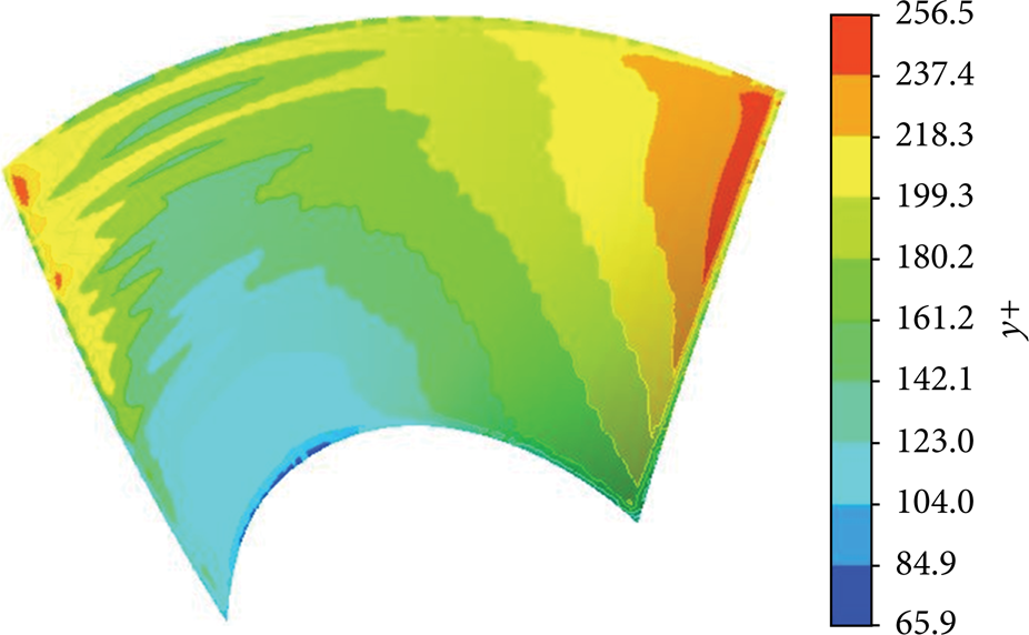
Contours of the y+ value on the wall of the impeller.
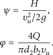
The designed pump head coefficient (ψ) is 0.216 under the designed flow coefficient (φ) (0.219). In this study, ψ and φ are defined as follows:
3. Numerical Simulation Methods
3.1. Solution Strategy
The commercial software FLUENT is used for the simulation, with the transport equations being solved using a finite volume method. The effects of turbulence are modeled using the realizable k-epsilon model. A second-order upwind scheme is used for the discretization of governing equations. Numerical convergence is set to a maximum of 10−5. In the steady state, the simulation is defined by means of multiple reference frame technique, in which the impeller domain is set as a rotating frame of reference while the other domains are set in a stationary frame. No-slip condition is assumed on all the solid walls.
3.2. Inlet Condition
The inlet boundary is set upstream from the impeller leading edge more than 3.5 times of the inlet diameters. The velocity inlet is applied at the inlet boundary, whose profile is assumed to be uniform. The turbulence properties are set to turbulence intensity of 5.89% and inlet hydraulic diameter.
3.3. Outlet Condition
The outlet boundary is placed downstream from the outside wall of the pump casing 3 times of the outlet pipe diameters. A constant pressure is specified at the outlet for all cases without consideration of cavitation.
4. Results and Discussions
4.1. Grid Independence Test
Grid independence verification is takien into consideration at designed flow rate 1.0 Q0 using the head as the validation parameters for the pump with the casing of model 1 and model 2. Figure 5 shows the head as a function of grid cell numbers from 2.5 million cells to 7.5 million cells. The results show that the head gradually increases as the cell number increases, and it begins to get stable when the cell number is close to 6 million. The relative error for the last two data is below 2%.
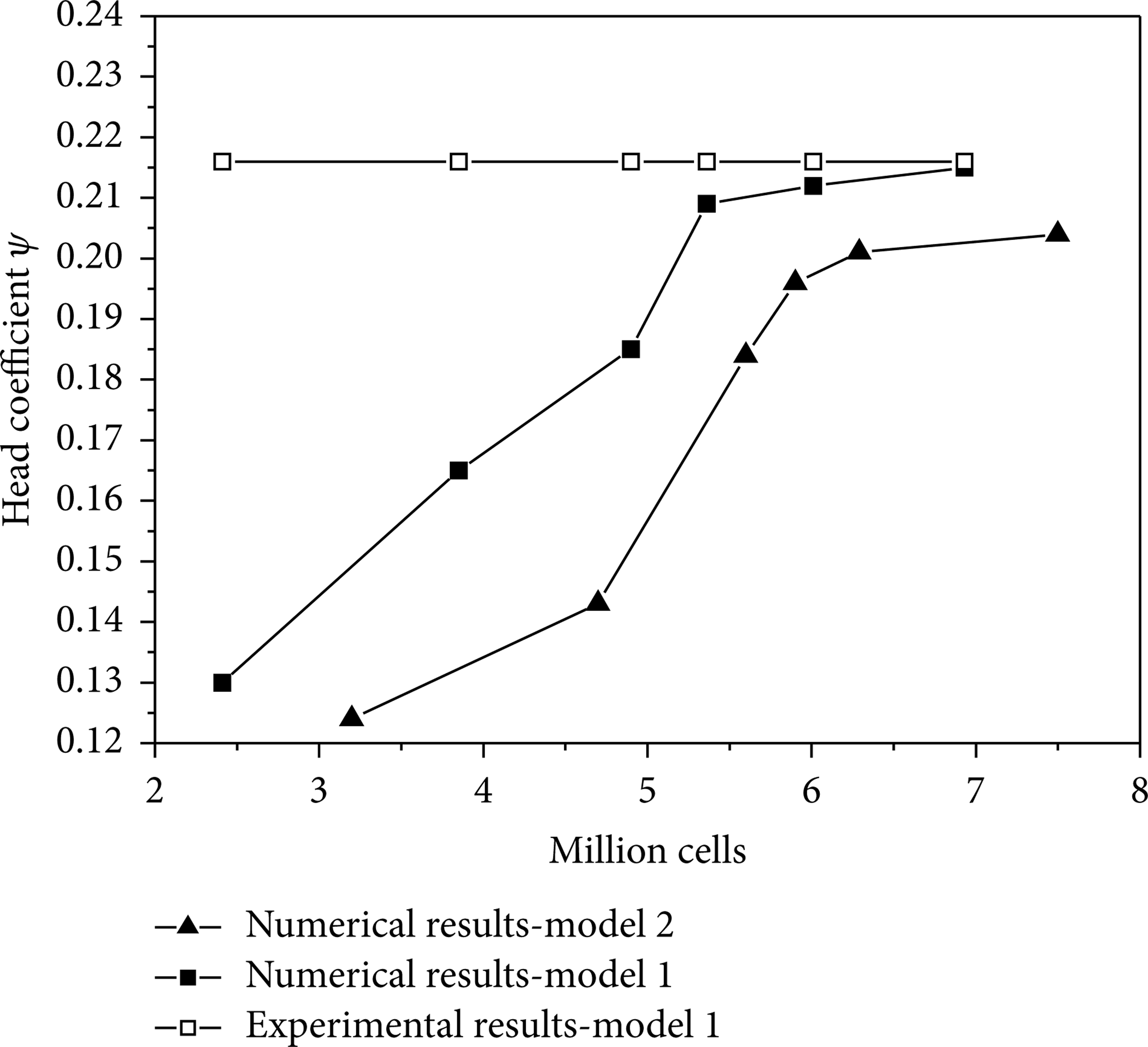
The results of the grid independence.
By considering the compromise between numerical accuracy and computational time cost, the grid with 6.0 and 6.3 million cells, respectively, for model 1 and model 2 is selected to perform the following studies.
4.2. Performance Analysis
In the following studies, the head H, H v and the head loss ΔH are determined by the pressure difference between the surface P2 and P1, P4 and P1, and P4 and P3, respectively, as presented in Figure 1(b), while P3 is set 2.8 times of outlet pipe diameter from the surface P2. In all the presented figures, the words “m” and “effi.” are the abbreviation for the words “model” and “efficiency,” respectively.
4.2.1. The Effect of the Position of Diffuser Relative to the Pump Casing
With respect to the position of guide vanes assembled in the pump, it is initially placed entirely outside of the pump casing as shown in Figure 2(b). In order to analyze its effect on the pump performance, the position of the guide vanes is gradually moved towards the inside of the pump casing. According to the distance moved into the pump casing based on the model 2, three models are established, respectively, which are model 2 with the diffuser placed entirely outside the pump casing, model 21 with the diffuser placed half inside the pump casing, and model 22 with the diffuser placed entirely inside the pump casing. Through the numerical simulation of the three models under different flow rate from 0.5 Q0 to 1.1 Q0, the detailed pump performance is obtained and compared with each other, as shown in Figures 6(a)–6(c).

(a) Performance curve comparison with different locations of guide vane relative to pump casing. (b) The comparison of pump head at guide vane outlet under different locations of guide vane relative to pump casing. (c) The comparison of head loss at the pump casing under different locations of guide vane relative to pump casing.
As shown in Figures 6(a) and 6(b), compared the models with cylindrical casing to the experimental model (model 1), it can be found that the models with cylindrical casing are presenting worse head and efficiency performance in the whole studied flow rate range. However, with respect to the head obtained at the outlet surface of the diffuser, it is larger than that of model 1 at the flow rate higher than 0.75 Q0 but smaller at the flow rate lower than 0.75 Q0. Therefore, it is not the flow in the diffuser passage that causes the head and efficiency drops in the whole flow rate because of different structure for the pump casing.
In addition, with altering the position of the diffuser relative to the pump casing, the head obtained at the pressure outlet surface or the outlet of the diffuser does not present obvious difference, as shown in Figures 6(a) and 6(b), respectively. But the increment magnitude of best efficiency at the designed flow is improved up to about 3% by moving the diffuser to be half inside the pump casing.
The head loss in the pump casing is shown in Figure 6(c). It illustrates that, under lower flow rate than 0.75 Q0, it keeps almost stable for the head loss in the pump casing relative to the total head. At larger flow rate than 0.75 Q0, the head loss grows when the flow rate increased. In contrast, with regard to the model 1, the loss keeps almost constant in the whole flow rate range and is much lower than that in cylindrical casing. Furthermore, the loss difference between two kinds of pump casing presented in Figure 6(c) gets growing with the flow rate increasing. That is the reason why the head of model 1 in Figure 6(a) is much higher than that of other models.
Moreover, the head loss of the pump casing in model 21 with the diffuser placed half inside the pump casing is lowest compared with other two models, which is in accordance with the performance curves as shown in Figure 6(a).
In conclusion, it has little impact on the pump head but a few impacts on the pump efficiency by altering the position of the diffuser relative to the pump casing. And when the diffuser is placed half inside the pump casing, the head loss in the pump casing is lowest and the efficiency gets about a 3% rise. Moreover, the different type of pump casing results in great difference on the pump performance.
4.2.2. The Effect of the Structural Size of Pump Casing
Keeping the position of the guide vanes unchanged, the effect of the structural size of pump casing is studied such as the length L and the radius R. And five sets of different dimensions are employed, as shown in Table 1.
Figures 7(a)–7(c) compare the pump performances of models with different structural size. According to Figure 7(a), it can be seen that, with the a little extending length L of pump casing from 500 mm to 750 mm, the pump efficiency diminishes approximately by 10% at the designed flow rate while the head just drops a little. However, the head and efficiency both show little deviations with a further increasing size. Comparing Figure 7(a) with Figures 7(b) and 7(c), it can be concluded that it is the loss in the pump casing that causes the difference in pump performance with the change of the structural size, as discussed in the previous section. And the increasing size of casing is not so conductive to the pump head.

(a) Performance curve comparison under different structure size of pump casing. (b) The comparison of pump head at guide vane outlet under different structure size of pump casing. (c) The comparison of head loss at the pump casing under different structure size of pump casing.
In conclusion, when the length of the casing is extended from the size that is equal to the diameter of the outlet pipe to that larger than the diameter of outlet pipe, the pump efficiency dropped remarkably while the head just reduces a little.
4.3. Flow Filed Analysis
Since the loss is mainly caused by the flow in the pump casing, the internal flow field of the pump casing and outlet pipe is analyzed to identify how the structure of the casing influences the pump performance, such as the distribution of the pressure; the streamline and the velocity vectors are presented in Figures 8–12. Figures 9–10 show the pressure contours in the pump casing and outlet tub on the plane which is normal to the rotation axis and at the center line of the outlet pipe. Figures 11–12 show the velocity vector in the pump casing and the outlet pipe on the plane which is defined by the rotation axis and the center line of the outlet pipe.

(a) The streamline distribution for the pump casing of model 1 at designed flow rate Q0. (b) The streamline distribution for the pump casing of model 2 at designed flow rate Q0. (c) The streamline distribution for the pump casing of model 21 at designed flow rate Q0. (d) The streamline distribution for the pump casing of model 6 at designed flow rate Q0.
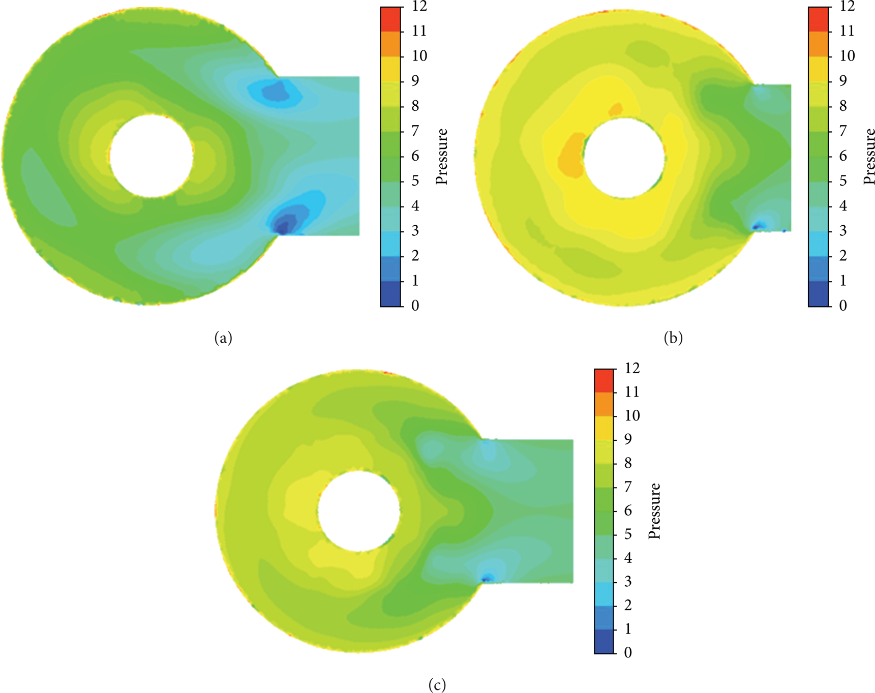
(a) The pressure contours for the pump casing of model 2 at designed flow rate Q0. (b) The pressure contours for the pump casing of model 21 at designed flow rate Q0. (c) The pressure contours for the pump casing of model 22 at designed flow rate Q0.

(a) The pressure contours for the pump casing of model 3 at designed flow rate Q0. (b) The pressure contours for the pump casing of model 4 at designed flow rate Q0. (c) The pressure contours for the pump casing of model 5 at designed flow rate Q0. (d) The pressure contours for the pump casing of model 6 at designed flow rate Q0.
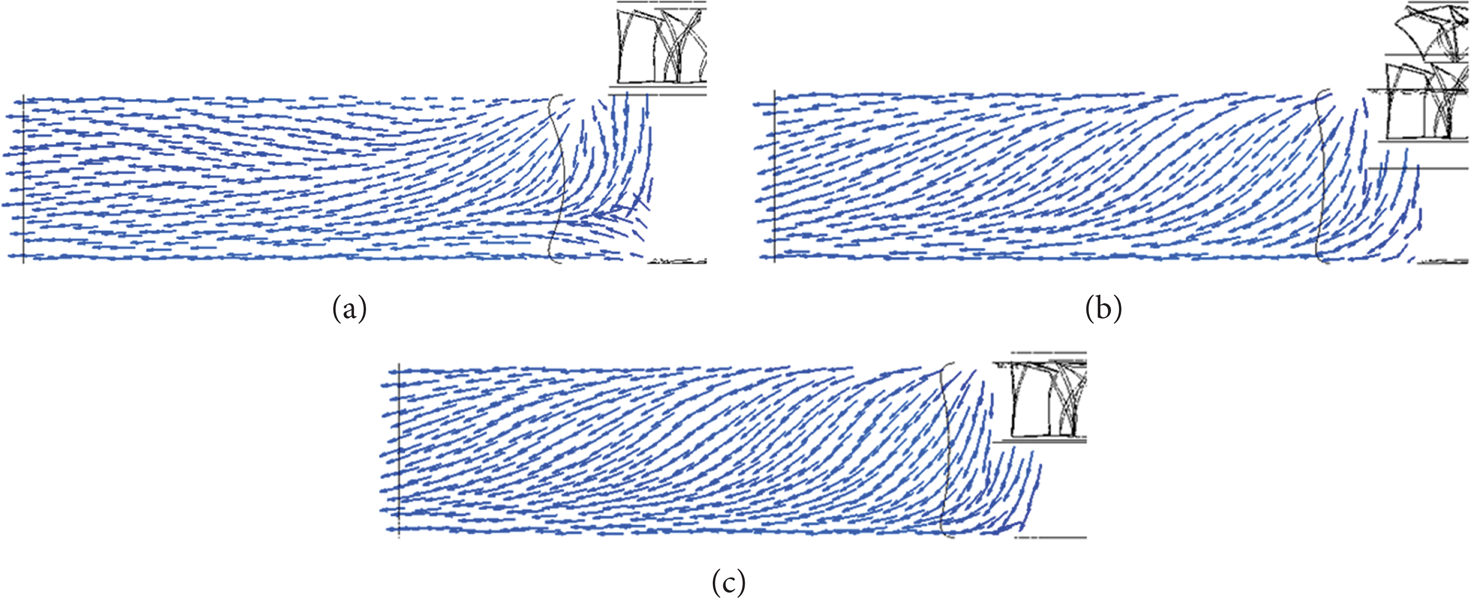
(a) The velocity vectors for the outlet pipe of model 2 at designed flow rate Q0. (b) The velocity vectors for the outlet pipe of model 21 at designed flow rate Q0. (c) The velocity vectors for the pump casing of model 22 at designed flow rate Q0.

(a) The velocity vectors for the outlet pipe of model 3 at designed flow rate Q0. (b) The velocity vectors for the outlet pipe of model 4 at designed flow rate Q0. (c) The velocity vectors for the outlet pipe of model 5 at designed flow rate Q0. (d) The velocity vectors for the outlet pipe of model 6 at designed flow rate Q0.
Firstly, comparing the flow in different type pump casing, like the model 2 and the model 1, it is evident that the flow in the model 1 is more stable and much better than that in model 2, as shown in Figures 8(a) and 8(b). The streamline in the pump casing of model 1 is almost parallel to the flow passage, without backflow and vortex. However, due to the structure feature of the pump casing of model 2, the flow is distributed in a disorder way. There are vortexes at the bottom of the casing, and curved flow occurs from bottom to top and from left to right. These unstable flows cause the head and efficiency to be much lower than that of model 1, as shown in Section 4.2.
Secondly, the flow field of the model with the same type casing is analyzed. In general, the fluids in the pump casing keep flowing in a disorder way and are not able to get an obvious improvement, no matter with altering the position of the guide vanes relative to the pump casing, nor with variously structural size, as illustrated in Figures 8(c) and 8(d).
However, by altering the position of the guide vanes relative to the pump casing, the pressure distribution improved as shown in Figures 9(a)–9(c). When the guide vane is placed entirely outside the pump casing, fluids with low pressure get accumulated on the corner of the pump casing and the outlet pipe, as seen in Figure 9(a). When the guide vane is moved to be half inside the pump casing, the low pressure zone get disappeared, as shown in Figure 9(b). With further movement that the guide vane is completely inside the pump casing, the pressure also distributes uniformly as before. The improvement of pressure distribution makes the pump efficiencyraised as presented in Figure 6(a).
Keeping the position of guide vanes unchanged, the pressure distribution is analyzed with gradually growing size of the structure, as shown in Figures 10(a) to 10(d). Comparing Figure 10(a) to Figure 9(c), with the a little extending of the length L from 500 mm to 750 mm, a large low pressure zone occurs in the outlet tub while the pressure in the casing does not differ much. Furthermore, the flow in the outlet tub gets improved with further increasing length L from 750 mm to 850 mm, as shown in Figure 10(b). And it gets no further improvement with extending it from 850 mm to 1020 mm as display in Figure 10(d). In addition, with the increasing radius R, comparing Figures 10(c) and 10(d) with Figure 10(b), the pressure distributes uniformly without significant changes. So it can be concluded that the length of the pump casing gives much greater impacts on the flow field than the radius of the pump casing.
In addition, from the velocity vector distribution in the outlet tub, as presented in Figures 11(a) to 11(c), it can be found the fluid in the outlet pipe flows in a curved way instead of being parallel to the passage. This kind of flow would induce pressure pulsation and vibration, which is harmful to the safety concern. With altering the position of guide vanes, this flow characteristic does not get better. When the size of the pump casing gets firstly increasing, the flow in the outlet tub still does not improve as shown in Figure 12(a). But the fluid in the outlet pipe changes to flowing parallel to the passage with secondly increasing size as shown in Figure 12(b). And the flow gets stable with further increasing size as shown in Figures 12(c) and 12(d).
In conclusion, though the streamline distribution in the cylindrical casing is not improved with the change of the position and the size, the unstable flow in the casing causes huge loss and results in a lower pump efficiency compared with the experimental model. By moving the position of guide vanes half inside the casing, the pump efficiency gets increased. With the growing size of the casing, the pump efficiency drops and the flow in the outlet tub can be improved.
Considering both the hydraulic performance and the flow field, it can be found that the pump casing of model 4 is the optimal one with the diffuser assembled inside.
5. Conclusions
A numerical research on the effect of the pump casing on the pump hydraulic performance and flow field of a mixed-flow pump has been carried out. The effect of the pump casing geometry parameters and the position of guide vanes placed in the pump has been investigated, respectively. And through the performance and flow field analysis, the following conclusions are drawn.
It is not conductive to the pump performance and flow field in the pump casing when the pump casing is designed in cylindrical shape compared with the experimental casing. Moreover, it is the flow in the pump casing that causes the remarkable performance difference.
For the cylindrical casing, the efficiency gets a little rise when the guide vane is placed half inside the pump casing. Meanwhile, it is conductive to eliminate the low-pressure fluids accumulated at the corner of the pump casing and the outlet pipe but not helpful to improve the curved flow in the outlet pipe.
The flow in the outlet pipe can be improved by increasing the structure size of pump casing. In this way, the pump head and efficiency gets an obvious drop when the length of the casing is set to be larger than the diameter of the outlet pipe, compared with the prototype casing. And the length of the casing plays greater impact on the pump performance and flow field than the radius of it.
The pump of model 4 with the guide vane placed entirely inside the pump casing presents better hydraulic performance and flow field distribution. This kind of structure can be applied in the reactor coolant pump and some high flow-rate circulating pumps. And its final structural size should be determined by considering the compromise between the structural compactness and performance requirements.
Footnotes
Nomenclature
Acknowledgment
This study was carried out as part of National Natural Science Foundation of China (no. 51276213) and Science and Technology Program of Zhejiang Province, China (no. 2012R10001-07). The support is gratefully acknowledged.