
Abstract
The resistance of gas flow in microchannels is higher because of the relatively more importance of interfacial effects at microscale. We studied the effective resistance of gas from the wall interactions, the ends effect, and the rarefication effect quantitatively using the three-dimensional (3D) direct simulation Monte Carlo (DSMC) method. The effective resistance is enhanced by the wall interactions, increasing exponentially as the concerned walls distance decreases. For short microchannels, the ends effects from both inlet and outlet also raise the effective resistance of gas flow in microchannels following a reciprocal exponential relationship with the aspect ratio of length to height. The gas rarefication strengthens the effective resistance enhancement by either the wall interaction effects or the ends effects. This work turns a complicated micromechanical problem into simple available formulae for designs and optimization of microengineering.
1. Introduction
It is now very important to fully understand the gas flow and heat transfer mechanism in microchannels because of various applications in microelectronic cooling systems, bipolar plates of fuel cells, compact heat exchangers and reactors for material processes, and advanced propulsion systems [1, 2]. The gas flow characteristics in microchannels does not agree well any more with the classical continuum theories because of slippage, compressibility, thermal creep, and so on [2–9]. The resistance in microgas flow has been one of the most arrestive concerns among scientists and engineers. Quite a few experiments have been performed on the friction constant (f · Re) in microchannel gas flow; however the results are inconsistent, with some [10] higher than while some others [11, 12] lower than the predictions based on the classical continuum theories. The studies with both experiments and numerical simulations showed that the inconsistencies might come from the relatively larger roughness degree [13], the nonnegligible effects from the entrance and exit regions [14, 15], the larger effects of compressibility [16] and the rarefaction [17] in microchannels, or even the instrument errors [16]. Despite of much progress in this topic, the quantitative description of effective resistance of gas flow in microchannel and the fundamental understanding of microscale gas flow are still not sufficient to the authors' best knowledge.
There are three major interfacial effects: the wall interaction effect, the end effect (including inlet and outlet effects), and the rarefied gas effect, dominating the effective resistance of gas flow in microchannels different from the bulk flow or the continuum flows. In this work, we introduce an effective resistant force to describe the overall resistance of gas flow which is induced not only by the viscosity of gas but also by all the interfacial effects in microchannels. Our object is to find the quantitative formulations for the effective resistance with the related key factors of interfacial effects in microchannels by numerical simulations.
2. Numerical Methods
2.1. Direct Simulation Monte Carlo Method
The direct simulation Monte Carlo (DSMC) method is a probabilistic simulation method based on molecular motion and statistical principle to simulate rarefied gas flows [18] or microgas flows [19]. The position, velocity, and other information are stored and modified in every time step by tracking the motions, collisions, and interactions with boundaries of all particles. The key ideas of DSMC method are the uncoupling of molecular motion and collisions during the time step Δt, and the simulation of molecular collisions by disregarding molecular position coordinates in the spatial cell in the condition that the time step Δt is much smaller than the mean collision time, and the spatial steps Δx, Δy, and Δz are much smaller than the molecular mean free path, respectively [20]. In this work, the variable hard sphere (VHS) model and the diffusive wall boundary condition are used for the collision processes. We consider gas flows in straight microchannels driven by a pressure drop, and the pressure boundaries at the inlet and outlet are implemented using the method proposed by Wang and Li [21], which actually assumes uniform pressures at inlet and outlet. The code has been tested and validated by various previous studies [20–23]. The 200 × 40 uniform rectangular cells with 4 × 4 subcells in each cell were applied to ensure the subcell size is smaller than the local mean free path in the simulations [20]. Over 1 × 10⁵ molecules were simulated, and the sample sizes were over 3 × 10⁵. Convergence was also verified by monitoring mass balance maximum errors whichwere less than 0.3%.
2.2. Mathematical Model
For microgas flows, the Knudsen number defined as the ratio of gas mean free path to the characteristic length of channel (Kn = λ/H withλ representing the gas mean free path andH the channel height) may be so high that the flows fall into the slip or even the transition flow regime. After simulations using the molecule-based DSMC method, we are aiming to summarize the effective resistance f based on the continuum momentum equation to bridge up the multiscale problem as follows:
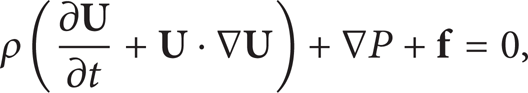
where ρ is the gas density,

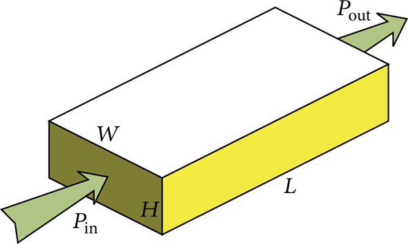
where A denotes the area of cross-section, F the overall effective resistance force, and Q m the mass flow rate. The subscripts 1 and 2 represent the inlet and the outlet, respectively. The effective resistance per unit volume is therefore calculated by

where the bars denote the average values across the section 1 or 2, Δp the overall pressure gradient, q the mass flux per unit area, and L the length of the microchannel.
As mentioned above, we consider three major interfacial effects: the wall interaction effect, the end effect (including inlet and outlet effects), and the rarefied gas effect, which influence the effective resistance of gas flows in microchannels. For a straight channel with a rectangular cross-section, the wall interaction effect varies with the width-height ratio (s = W/H), which will be illustrated in details in the next session. The relative importance of the end effects from both inlet and outlet depends on the dimensionless channel length (l = L/H). With the rarefied gas effect considered as well, the effective resistance per unit volume of gas flow in microchannels (f) can be formulated as a function as (4), and the task of this work is to find the exact formulation of this function:
3. Results and Discussion
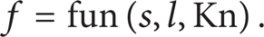
Consider nitrogen gas flows through a three-dimensional (3D) straight microchannel with a rectangular cross-section driven by a pressure difference between inlet and outlet as shown in Figure 1. The channel is L in length, W in width, and H in height of the microchannel, respectively. The parameters of properties of the nitrogen gas are from the book of Bird [18]. We use the state of gas at the inlet as a reference to determine the cell size and the time step of our simulations. The cell size is taken as a half of the molecular mean free path and the time step as a half of the mean collision time of the reference gas [21].
Sketch of the simulated 3D geometry of microchannel, where W, H, and L denote the width, height, and length of the channel, respectively. Pin and Pout are the local pressures at inlet and outlet.
3.1. Wall Interaction Effects
The wall interaction effects refer to the effects on the effective resistance when the distance of two concerned walls varies. This effect differs from the rarefication effect which is determined by the Knudsen number. For example, for a gas flow in a 3D channel as shown in Figure 1, the rarefication effect is characterized by the channel height H (assuming H ≤ W), while the wall interaction effect relates to the channel W for a given H, if the two side walls are movable and concerned. When the wall interaction effect is studied, the width-height ratio s is treated as an independent variable, increased from a small value to a large one. In the simulation, we keep the height as a constant and vary the width of the microchannel. If the width is large enough, the 3D flow approaches a 2D flow.
In this work, the height of the microchannel (H) is 0.2 μm, and the length is 5 μm. The inlet and outlet pressures are 15 kPa and 10 kPa, respectively. The independent variable s is 1, 2, 4, 8, 10, and 15 for case 1 to 6, respectively. The gas temperature at the inlet and the wall temperature are both at 300 K. After simulations, we calculate the properties of gas flow in microchannel, including the local density and velocity components [18, 21]. The effective resistance can therefore be calculated based on (3). In our simulations, the inlet and outlet pressures difference is kept constant, and therefore we introduce a new variable, f i which means the inertial force of the gas flow. The direction of f i is opposite to the pressure difference, and its value is calculated by
The symbols in Figure 2 are results from our simulations of the inertial force f
i
versus the width-height ratio s, while the solid line is a fitting relation following a reciprocal exponential law of

where c1, c2, and c3 are constants. The constants may vary case by case, but the formulation form holds, which will be discussed later in this work.

Inertial force f
i
versus the width-height ratio s, where f
i
= Δp – f. The symbols are results from our DSMC simulations, and the dash line is the fitting curve at a function of
In a microchannel gas flow, when the width-height ratio s is at a small value, the wall interactions have a significant effect on enhancement of the effective resistance. The effective resistance increases at an exponential law as the walls distance decreases. If the width-height ratio s ≫ 1, the 3D gas flow behavior approaches a 2D one. In our current simulations of this work above, the effective resistance enhancement of 3D gas flows is less than 3% or negligible, compared with the corresponding 2D gas flows when the width-height ratio is s ≥ 10.
3.2. End Effects
The end effects from inlet and outlet of a channel have been reported earlier [14, 15] to be a nonnegligible factor in microflows; however no quantitative studies have been presented to show how the end effects influence the effective resistance in microchannel gas flows up to now. In order to characterize the end effects exactly, we propose a “truncation channel” scheme inspired by an experimental technology [13]. The scheme is illustrated in Figure 3. First, we need a long microchannel as a reference. Let the gas flow through the long channel driven by a pressure difference, and we can get the pressure distribution along the channel by DSMC simulations. And then we cut the long channel to shorter ones gradually from one end. For examples, if we are focusing on the outlet effect, we cut the channel from the outlet as shown in Figure 3(a); otherwise we cut the channel from the inlet end to consider the inlet effects. After the channel is cut, we have a new end and assign the pressure at the same position of the long reference channel as the new boundary condition to this end. By comparing the resistances of the shorter channel with the reference one, we can figure out the end effects on the effective resistance enhancement changing with the channel length. It is clear that such effects are negligible, when the channel is long enough, and more and more significant as the channel becomes shorter and shorter.

Illustration of the “truncation channel” schemes to study the end effects. Pin and Pout are the inlet and outlet pressures of the reference long channel. P1, P2, and P3 are the local pressures on the reference channel where we may truncate the channel to form a new end. We assign P1, P2, or P3 as the pressure boundary condition (Pin′ or Pout′) to the new end of the truncated channel.
The reference microchannel is 5 μm in length (L) and 0.2 μm in both width (W) and height (H). The gas is driven flowing by a pressure difference of 15 kPa to 10 kPa. The effective resistance is calculated by (3). Based on the “truncation channel” scheme, the resistance enhancement by the end effects is characterized by the ratio of resistances between the truncated channel and the reference channel at the corresponding length.
Moreover,
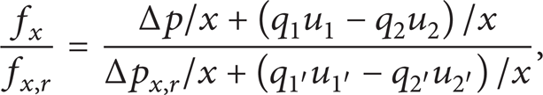
where x denotes the length of the truncated channel, f x is the effective resistance per unit volume of truncated channel, while f x, r is the local effective resistance per unit volume of reference channel from the inlet down to x position for considering the outlet effect or from the outlet up to x position for the inlet effect. The subscripts 1 and 2 denote the real inlet and outlet of the truncated channel, while the subscripts 1′ and 2′ are the corresponding positions on the reference channel. For instance, when the outlet effect is studied, the subscript 2′ does not mean the real outlet position of the reference channel, but the position x away from the inlet along the channel. Δp x, r denotes overall pressure gradient for the concerned region on the reference channel.
Figure 4 shows the effective resistance enhancement from the ends effects varying with the dimensionless truncated channel length l = x/W. The symbols are the simulation results, and the solid lines are fitting curves. The results indicate that the effective resistance enhancement rate (f x /f x, r ) varies with the channel length (l) at a reciprocal exponential law as


The effective resistance enhancement by the end effects changing with the dimensionless length of microchannels, where f
x
denotes the effective resistance of the truncated channel at length x and f
x, r
the effective resistance of the reference channel at the corresponding region. The symbols are results from our DSMC simulations, and the dash lines are the fitting curves at a function of
Since the properties of gas flow, such as velocity and temperature, drastically change near the ends region (inlet and outlet) [15, 22, 24, 25], the resistance at the ends is much larger than other parts of channel. When the microchannel is long enough, the end effects are negligible. However if the channel length is comparable with the channel width (l ~ 1), the ends may have a significant effect by enhancing the effective resistance. The results also indicate that the end effects are limited to a finite region. In our simulations above, when the dimensionless length l reaches 2~4 or above, the effective resistance enhancement is less than 3%.
3.3. Rarefied Gas Effects
The rarefied gas effects on the effective resistance enhancement are studied by changing the Kn number of the gas flows in microchannels. In this study, we are concerning how the wall interaction effects or the end effects vary with a different Kn number. To do this, we just simply set the inlet and outlet pressures at 150 kPa and 100 kPa, respectively, in the same microchannel to reduce the Kn number ten times smaller.
When the gas gets ten times denser, the wall interaction effects are dramatically enhanced because the gas molecules colloid much more with the walls. The inertial force calculated by (3) may differ in orders of magnitude for these two Kn numbers. In order to make a comparison in the same figure, we introduce a dimensionless inertial force normalized by the corresponding 2D gas flow under the same boundary conditions as follows:
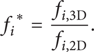
Figure 5(a) indicates that the inertial force and therefore the effective resistance force vary with the width-height ratio at a very similar exponential law even though the Kn number changes ten times, and the gas flow status transfers from the transition region (Kn = 1.787) to the slip region (Kn = 0.1787). A larger Kn number leads to a wider region of the wall interaction effects. When we consider the ends effects for different Kn numbers, as shown in Figures 5(b) and 5(c), the gas rarefication strengthens the effective resistance enhancement by the ends effects of gas flow in microchannels.
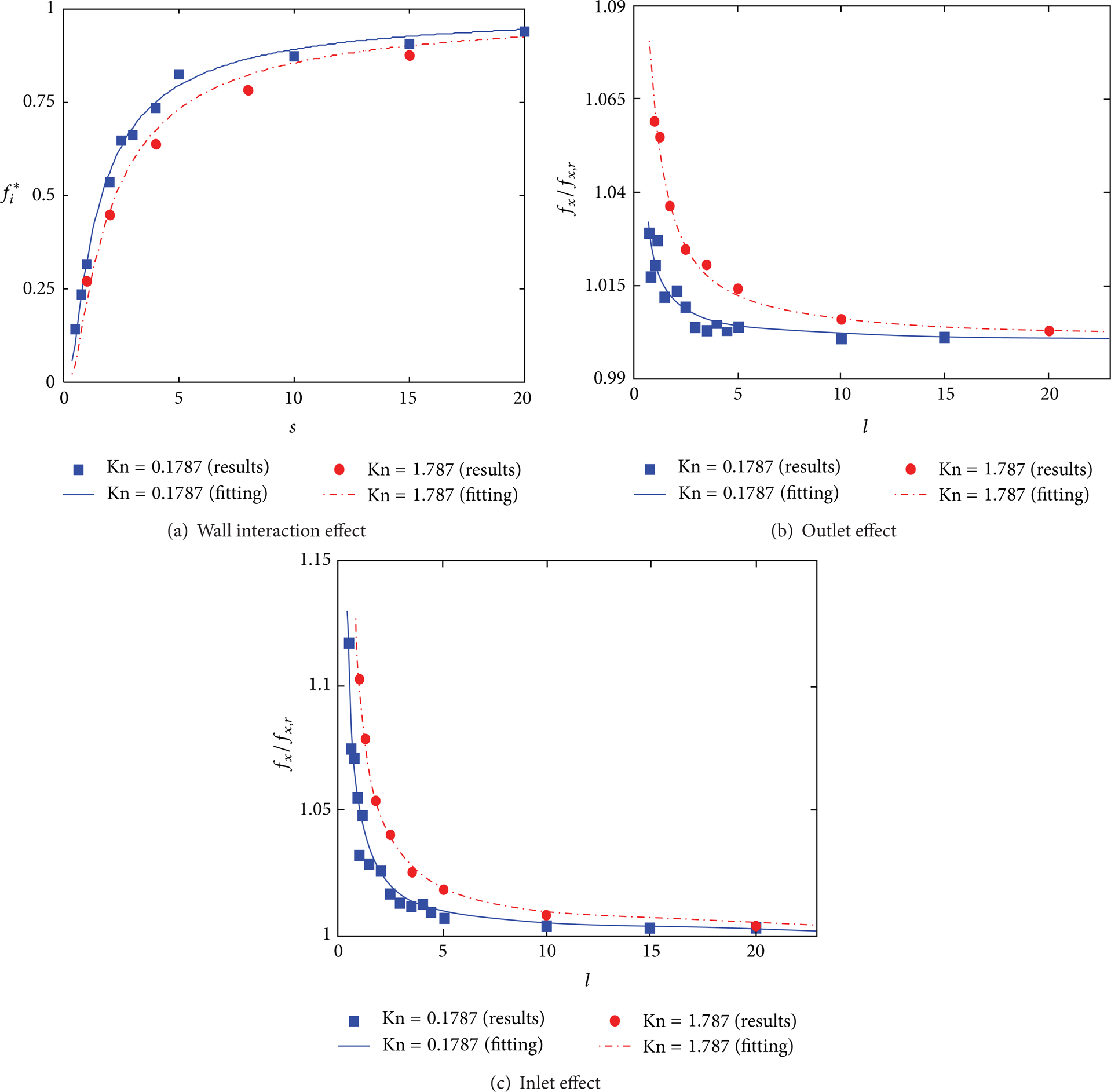
Comparison of effective resistances between Knin = 1.787 and Knin = 0.1787. Symbols denote the simulation results, and the curves are fitting ones. The symbols are results from our DSMC simulations, and the dash lines are the fitting curves at a function of
4. Conclusions
As well known that the resistance of gas flow in microchannels is higher than that in bulk or continuum flows because of the relatively more importance of interfacial effects at microscale, in this work, we first quantified the effective resistance enhanced by the wall interactions, the ends effect, and the rarefied gas effect using a 3D direct simulation Monte Carlo (DSMC) method. For a narrow microchannel (small H), the effective resistance increases at an exponential law as the distance between side walls (W) decreases. For a short microchannel, the averaged resistance density is higher than that of a long channel because of the dramatic variation of gas flow structures at the inlet and outlet regions. We proposed a “truncated channel” scheme to study the ends effects and found that both inlet and outlet effects raise the effective resistance of gas flow in microchannels following a reciprocal exponential relationship with the aspect ratio of length to height. After comparing two cases with different Kn numbers, we found that the gas rarefaction strengthens the effective resistance enhancement by either the wall interaction effects or the ends effects of gas flow in microchannels. This paper provides simple formulae available for designs and optimization of microengineering from complicated micromechanics.
Footnotes
Acknowledgments
This work is financially supported by the NSFC Grant (no. 51176089), the Tsinghua Initiative Scientific Research Program, and the startup funding for the Recruitment Program of Global Young Experts of China (no. 320503002).