
Abstract
This paper deals with static balancing of closed-loop mechanisms. The long-term goal of the research is enhancing the performance of parallel robots by means of effective static balancing strategies that take into account the system dynamic behaviour. In this contribution, the influence of mass-balancing on the elastodynamic performance of a four-bar linkage, intended as the simplest example of closed-loop mechanism, is experimentally investigated. The design of the experimental apparatus is discussed and the results of tests on both an unbalanced linkage and its balanced variant are presented. Base-transmitted forces and vibrations are monitored for constant-speed operations and for velocity ramp tests in order to characterize the elastodynamic behaviour of the linkages. The analysis is supported by implementing a flexible multibody model of the experimental apparatus that enhances the interpretation of the experimental data.
1. Introduction
Several studies dealing with gravity compensation of closed-loop linkages may be found in the literature [1–6]. The main benefits potentially achievable are [7]: (i) lower and more uniform load requirements for actuators, leading to improved energy efficiency and lighter motors; (ii) size reduction of safety brakes (which are normally required for keeping a mechanism at rest when the motors are switched off or an actuator failure occurs), thus resulting in further weight saving and lower energy consumption. For closed-loop mechanisms the most significant advantages are expected when low/moderate dynamics are involved and/or a remarkable weight has to be sustained at rest for long time intervals [6]. These working conditions are met in applications such as Parallel Kinematics Machines (PKMs) for machining operations or parallel robots for surgery assistance. Consequently gravity compensation appears a viable strategy to improve their working performance. However such machines, in particular PKMs, may also operate with high velocities and accelerations for short time intervals (e.g., during fast movements for tool positioning), thus experiencing high transient loads generated by inertia actions. The introduction of balancing elements may intensify these effects by further incrementing inertia actions, thus possibly worsening the overall mechanism dynamics [8–10]. Indeed an increment of driving actions and joint reactions is somewhat expected during these transients. In addition, the presence of high transient loads may excite the system natural frequencies [10–15]. While the former phenomena may be deemed as acceptable if occurring over a small percentage of the working cycle, the latter ones might be revealed particularly critical, since high vibration levels are ordinarily detrimental for the performance of any machinery. It is worth noticing that a dynamic balancing approach, possibly suggested by the presence of non-negligible inertia actions, does not appear as a viable solution. Indeed the practical implementation of dynamic balancing strategies is generally difficult to achieve [16, 17], and potential elastodynamic issues may not be removed.
This research aims at investigating actual benefits and drawbacks brought about by static balancing to closed-loop mechanisms. The long-term goal is the definition of feasible balancing strategies for enhancing the operation of parallel robots. The above-mentioned considerations infer that the achievement of effective gravity compensation strategies for closed-loop mechanisms necessarily requires a careful evaluation of all possible detrimental effects of balancing devices on the mechanism dynamic operation. In particular the analysis of elastodynamic aspects appears essential. The research started from a planar four-bar linkage, intended as the simplest example of closed-loop mechanism. In [18] an unbalanced mechanism and two balanced variants, respectively, obtained by mass and elastic balancing, were preliminarily investigated by means of numerical simulations. The study suggested that counterweights may significantly alter the system dynamic behaviour even for relatively low operating velocities, thus resulting in a critical limitation to the advantages of gravity compensation.
This paper deals with experimental analyses performed on two variants of a four-bar linkage, that is, an unbalanced mechanism and a statically balanced one, obtained by attaching counterweights to the crank and the rocker of the unbalanced linkage. The experiments were primarily meant to obtain reliable data concerning the critical issues of mass-balancing associated with the introduction of counterweights in a physical system and to possibly infer some general results to be extended to more complex mechanisms. An experimental apparatus was therefore arranged and tested in different working conditions to inspect the effects of balancing devices on several significant mechanical quantities related to dynamic operation. In particular, forces and vibrations transmitted to the base were measured during both velocity-ramp tests and operations at constant input speed. A flexible multibody model of the test rig was also implemented as a tool for supporting the analysis of the measured data.
The paper structure is as follows. Section 2 describes the experimental apparatus, the performed tests, and all the analysis tools used for processing the measured data. In Section 3, the results of the experimental campaign are presented and discussed. Finally, some conclusions are drawn in Section 4.
2. Experimental Setup and Test Protocols
The investigated mechanical system is a planar crank-rocker four-bar linkage. Its main geometrical and inertial parameters were defined consistently with [19], considered as a well-known reference example concerning balancing studies. The investigation focuses on the unbalanced mechanism (4B-U) and its mass-balanced variant (4B-M). The latter was obtained from the unbalanced linkage by adding counterweights to its crank and rocker (Figure 1). In order to achieve gravity compensation, the centre of mass (CM) of each component was estimated by the CAD models developed for the component design, whereas mass values were measured experimentally. Balancing parameters were determined according to the original technique reported in [18].
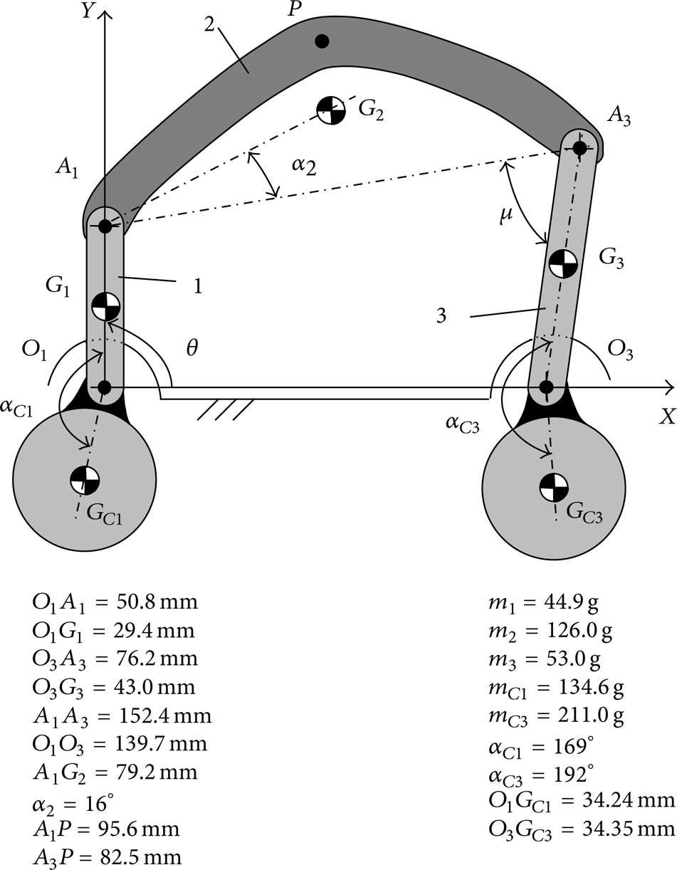
Schematic representation of the mass-balanced four-bar linkage considered in the study. The main geometrical parameters as well as the mass values of the links (m i ) and the counterweights (m Ci ) are reported.
In order to simplify the investigation, a strategy for removing transverse flexural or torsional-flexural deformations was pursued. Indeed, the presence of such phenomena may prevent experimental data to be correctly interpreted, without any benefit [10]. Therefore, a proper design of the experimental apparatus was adopted, to minimize dynamic deformations occurring out of the plane of motion during tests.
2.1. Experimental Apparatus
The experimental apparatus is shown in Figure 2(a). The requirement of planar deformations (i.e., vibrational modes mainly lying on the plane of motion) heavily influenced the design of the whole mechanism. The linkage and the loads acting on it (i.e., reaction forces and driving and inertia actions) were made symmetric with respect to the median plane, thus theoretically removing forces and torques able to trigger out-of-the-plane deformations. According to this approach, a completely symmetric geometry was adopted, with the crank being made in two halves and the rocker being a symmetric fork. Both links feature two separate supports on the base (as clearly visible in Figure 2(b)). In addition, a suitable cross-section yields high flexural stiffness orthogonally to the plane of motion for both members, thus further preventing lateral bending.
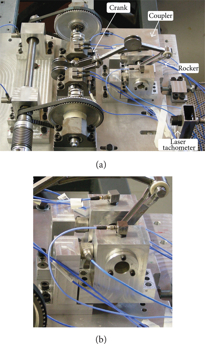
Experimental rig: (a) overall view and (b) close-up of the rocker supports.
The power transmission chain was designed for providing motor torque to both crank halves. Motion is transmitted to the shaft of each half by a timing belt, the shaft being connected to the corresponding pulley by a membrane coupling.
Figure 3 shows a schematic representation of the test bench. An asynchronous motor drives a high-speed shaft via a bellow coupling. The motion is transmitted from this shaft to low-speed shafts (referred to as input shafts) by means of two timing belts and their corresponding pulleys, which provide a speed-reduction ratio of 1: 4 (the pulleys having 18 and 72 teeth, resp.). An inverter allows speed regulation of the actuator.

Schematic diagram (top view) and sensor setup of the experimental rig.
The test bench allows the base reaction force acting on the rocker (
Piezoelectric accelerometers were conveniently placed in the test bench (Figure 2) to monitor the vibrations induced by the base-connected shafts on their supports. The accelerations detected along the X-axis in two of the eight available measuring points, named 3A and 7A (Figure 3), are presented and discussed hereinafter.
The test bench was also equipped with a laser tachometer (Figure 2(a)) for monitoring the angular position and velocity of the input shaft. A reflective tape located on one driven pulley marks the configuration characterized by a crank angle of 90° (as in Figure 1), referred to as θ0 (angles are measured from the X axis). The angular reference provides one pulse per pulley revolution, which is used for computing the shaft angular velocity.
2.2. Experimental Tests
Two different kinds of test were performed. In the first experimentation a constant velocity was imposed on the actuator. The test aimed at investigating the dynamic performance of the linkage during steady working conditions, when no external loads, aside from gravity, acted on the mechanism links. Several values of the motor speed were tested, in the range 240–2400 rpm, thus making the crank rotate within 60–600 rpm.
In the second experimentation, a slow linear velocity ramp (duration of 200 s) in the range 0–2600 rpm was imposed to the motor. The purpose was to investigate the resonances of the overall system in the bandwidth of interest, as usually done for rotating machinery, for which experimental modal analysis is rather impracticable.
An LMS SCM-05 data acquisition system was adopted for all measured signals. Acquisitions were performed with a sampling frequency of 5120 Hz. The duration of constant velocity tests was 25.6 s, whereas the acquisition time of velocity ramp tests was approximately equal to 180 s (signals being recorded for motor velocities in the range 120–2520 rpm).
Measured data were analysed in the time, frequency, and time-frequency domains.
2.3. Numerical Models and Simulations
A numerical model of the experimental apparatus was developed as a tool for enhancing the analysis of experimental data. Numerical simulations allowed several quantities not easily gaugeable to be monitored, thus providing a larger amount of information.
The numerical models of the linkages were derived from the CAD models used for designing the test bench. In particular, the moving links were implemented as flexible parts by means of finite element (FE) representation, with each member being meshed with 10-node tetrahedral elements. The other mechanism components (e.g., bearings and driving pulleys) were considered as rigid bodies, since they are expected to exhibit negligible deformations.
The flexible multibody model of the 4B-U was generated by assembling the FE models inside a multibody software environment. Lumped inertial parameters were adopted for rigid components.
The compliance of membrane couplings and belts, expected to provide major contributions to the deformation of the power transmission chain, was taken into account using lumped stiffness parameters. First attempt values of their torsional stiffness (reduced to the crank shaft) were, respectively, estimated according to the coupling datasheet and to the model proposed in [20].
The counterweights used in the experimental device are bulky steel disks, thus experiencing negligible local deformations. The numerical model of the 4B-M was consequently generated from the model of the 4B-U by adding further lumped parameters, to take into account the inertia of the balancing elements.
Kineto-elastodynamic (KED) simulations were performed to replicate the constant-velocity tests carried out on the experimental apparatus. Motion was imposed on both sides of the crank shaft by means of constant velocity functions. Different input velocities were tested up to 600 rpm.
Modal analyses were carried out for computing the modal parameters of the mechanical system. Since modal parameters depend on the mechanism configuration, natural frequencies and mode shapes were computed for several values of the crank angle.
3. Results and Discussion
3.1. Experimental Results
The results concerning force signals obtained from the constant velocity tests are first presented. Experimental data discussed hereinafter deal with the X component of the force only, being considered as the most interesting. The reported observations hold for all tested operating regimes.
The measured forces are highly repeatable over the input shaft revolution period for the entire length of acquisitions. The computed standard deviation remains in fact at acceptable values for all tested conditions (constantly under 10% of the averaged signal even when significant oscillations occur). Signals averaged over 5 periods are considered hereinafter for the analyses.
Force signals detected on the two sides of the rocker support match very well, thus confirming that the system exhibits the desired planar behaviour.
Figure 4 shows the comparison between the force transmitted to the base by the 4B-U and the 4B-M linkages running at 150 and 600 rpm crank speed. As expected, the measured force signals are characterized by a remarkable peak occurring where the transmission angle μ is at a minimum (Figure 1), that is, for θ – θ0 = 270°. The trends of the force peak and RMS values over the whole range of tested working conditions are reported in Figure 5. The analysis provides clear indications about the effects of counterweights on the mechanism operation: the mechanisms exhibit comparable values of the reaction force only for very low values of the running speed (Figure 5). As the angular velocity rises, the force amplitude increases, with the balanced linkage exhibiting a largely greater increment than the unbalanced one. This effect (noticeable starting from 240 rpm) becomes remarkable over 420 rpm.

Reaction force
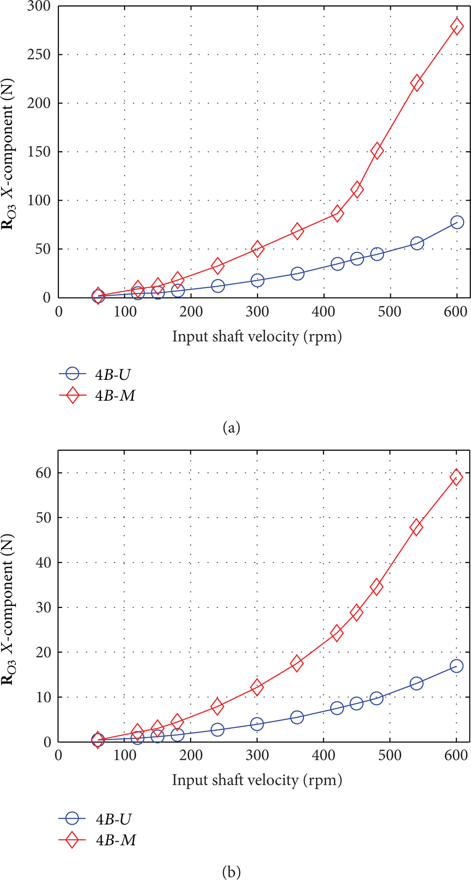
Statistics of the measured reaction force
Non-negligible oscillations affect the measured forces of both linkages, with their amplitude increasing as the input velocity rises. The vibration levels and the frequency content of the reaction force are investigated by means of both frequency and time-frequency analyses.
The power spectral density (PSD) computed in the range 0–800 Hz for the force signals relative to both linkages, functioning at the highest velocity, is reported in Figure 6. Figure 7 shows the results of the time-frequency analysis of the ramp test data, in the frequency band 0–450 Hz, by using a common colormap representation: the abscissa reports the frequency while the ordinate indicates the input shaft velocity; red tones denote higher amplitude of the vibrations; white solid lines follow the path of the meshing frequency of the timing belts (circle marker, meshing frequency being 72 times the input shaft rotation frequency) and its second and third harmonics (triangle and square markers, resp.). Time-frequency analysis allows one to distinguish between the effects related to the input velocity (whose frequency content varies along with the motor angular velocity) and the system resonances (not affected by the running speed variation).

Spectral analysis of the force signals at the input shaft velocity of 600 rpm.
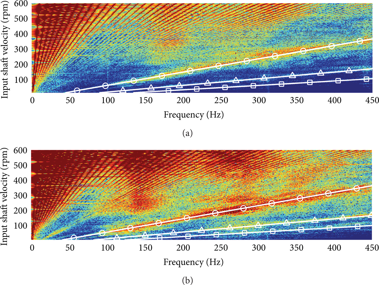
Time-frequency analysis of the velocity ramp data: (a) 4B-U and (b) 4B-M force signals. White solid lines show the meshing frequency and its second and third harmonics (circle, triangle, and square markers, resp.).
The most relevant contribution to the vibrations of both linkages lies in the range 100–400 Hz (Figures 6 and 7). Spectral components below this frequency range are related to the revolution period.
The spectra in Figure 6 show remarkable side bands separated by the rotation frequency of the input shaft. Moreover the time-frequency analysis in Figure 7 shows relevant spectral components related to the meshing frequency (and its harmonics). At low velocities such components are predominant, and they make it difficult to correctly detect the system resonances (e.g., the meshing frequency causes the significant oscillations observed for low speed values in Figure 4(a)). For higher running speeds the meshing effects are still relevant but they exert a weaker influence on the frequency band of interest.
The analysis clearly reveals two natural frequencies in the band 100–400 Hz for both tested mechanisms. These resonances are responsible for the most relevant frequency content characterizing force signals of both linkages. As expected, mass-balancing induces a significant reduction of the system resonances that causes a worsen elastodynamic behaviour even at low dynamics. The lower resonance, for instance, decreases from about 170–190 Hz, for the 4B-U, to about 130–150 Hz, for the 4B-M.
Although accelerations can be gauged more straightforwardly than forces, the investigation mainly focused on force signals. Indeed the analysis of acceleration signals did not allow the effects of counterweights to be unambiguously detected. As for constant velocity tests, Figure 8 reports the RMS values computed for the filtered signals (0–450 Hz low-pass filter) relative to 3A and 7A accelerometers (Figure 3), considering all speed values. The unbalanced and the mass-balanced mechanisms exhibit comparable vibration levels. The RMS curves are not characterized by a monotonic trend and they even show some intersections, and therefore they do not provide a clear interpretation of measured vibrations. The results of time-frequency analysis performed on the acceleration signals detected by the same transducers for the velocity ramp tests are shown in Figure 9. The spectral components related to the meshing frequency and its harmonics appear to be more relevant than in force signals, for both mechanisms, thus significantly influencing RMS values. Further system resonances in the band of interest are revealed, for example, the natural frequencies at about 70 and 110 Hz, which are not apparently affected by the introduction of the balancing masses.

RMS values of the acceleration of the experimental linkages for all tested velocities: (a) point 3A-X direction, (b) point 7A-X direction.

Time-frequency analysis of the velocity ramp data: (a) 4B-U and (b) 4B-M acceleration signals. White solid lines show the meshing frequency and its second and third harmonics (circle, triangle, and square markers, resp.).
The investigation of vibration transmission paths may be required for correctly identifying all the other sources of vibrations which affect vibration signals and hide the effects of counterweights. Indeed some of the observed natural frequencies, such as the relevant peak at about 300 Hz, are not revealed by force sensors. The described numerical models were specifically implemented for better understanding the unexpected phenomena which seemingly affect vibration measures. The observed effects are discussed in the next section, where the analysis of experimental data is further widened by means of the numerical models.
3.2. Numerical Results
The numerical results reported hereafter are obtained after some steps of model updating, carried out by means of manual iterations. The stiffness parameters of couplings and belts were set to 935 Nm/rad and 1260 Nm/rad, respectively. A model of viscous damper was associated with each stiffness parameter. Their damping coefficients were set to 5.73·10−2 and 1.72·10−1 Nms/rad, respectively. A constant damping ratio was also set (1%) for all mode shapes forming the modal basis of the flexible links.
The comparison between the reaction force computed by means of KED simulations and the experimental data, for the highest running speed, is reported in Figure 10. The X component of the reaction force
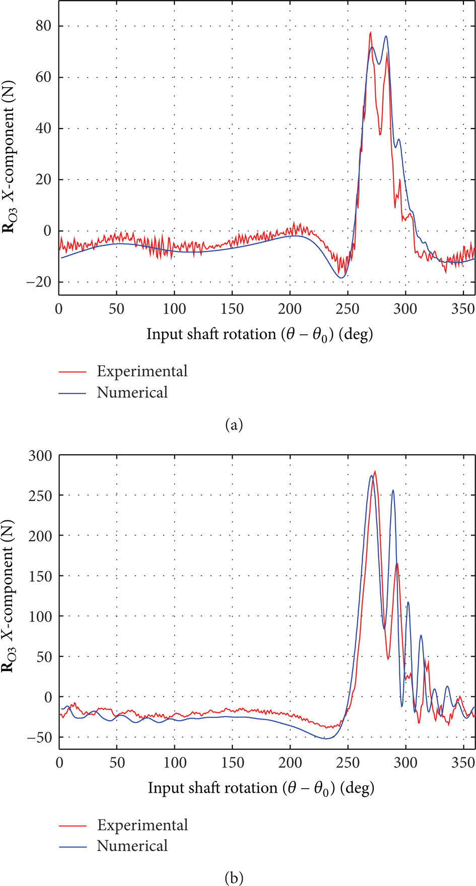
Comparison between experimental and numerical results of the reaction force
These results prove that an adequate correspondence between experimental and numerical data is attained, with slight discrepancies being considered acceptable. A finer tuning of the model parameters for further improving the model accuracy was not deemed worthwhile. Indeed the current study is focused on the investigation of static balancing techniques applied to closed-loop mechanisms and not on the mechanism itself. The obtained accuracy is considered satisfactory, and, for the purpose of this study, the numerical model is regarded as validated.
The natural frequencies computed by means of numerical modal analyses are reported in Figure 11 as a function of the crank angle (θ – θ0). The resonances are numbered according to the reciprocal order that they assume in the dead-point configuration θ s = 14°. The mode shapes up to the 4th one are common to both the mechanisms. The 1st mode shape mainly involves the coupler, which undergoes a flexural deformation out of the plane of motion. Both the 2nd and the 3rd modes exhibit deformations on the plane of motion: in the 2nd mode, deformations are mainly given by the transmission chain, with the other parts of the linkage basically undeformed; the 3rd mode involves torsional deformations of the transmission and flexural deformations of the links, with larger deformations of the rocker for the 4B-M. The 4th mode shape features a local torsional deformation of the crank.

First four natural frequencies computed through numerical simulations.
Natural frequencies vary with the mechanisms configuration, with the exception of the 4th resonance. The 1st and the 4th modes are basically not affected by the introduction of counterweights: in particular, the 1st natural frequency is common to both models, while the 4th one only shows a rather small variation (the resonance decreasing of about 5%). On the contrary, the 2nd and the 3rd mode shapes are significantly influenced by the balancing elements, with the 4B-M being characterized by a considerable reduction of the corresponding natural frequencies. In particular the 2nd resonance exhibits a decrement of about 19% (computed by considering the average frequencies over one complete crank rotation), while the 3rd one is characterized by a variation of about −10%. These results are consistent with the decrement of the system resonances revealed by the experimental analysis (Figures 6 and 7).
Figure 12 shows the continuous wavelet transform (CWT), computed by using a Morlet wavelet function [21], of the measured force signals for both linkages running at 600 rpm. The colormap representation shows the wavelet coefficients (absolute values) plotted as a function of the input shaft rotation and the frequency (abscissa and ordinate, resp.). Red tones represent higher vibration levels (the same scale is adopted for both mechanisms). The trend of the 2nd and 3rd natural frequencies predicted by the numerical models is also plotted (solid line).

Time-frequency analysis of the constant velocity data (600 rpm), CWT of the (a) 4B-U and (b) 4B-M force signals.
The frequency content detected in the force signals is consistent with the numerically computed resonances. The 2nd and the 3rd natural frequencies are reliably proven to be responsible for the severe vibrations affecting the balanced linkage, thus confirming the remarkably negative influence of counterweights on the mechanism performance.
CWT also provides an explanation of the modulation effects observed in Figures 6 and 7. Indeed side bands are consistent with both the variation of the detected frequencies (with the mechanism configuration) and the transient vibration phenomena.
The 1st and the 4th computed mode shapes are reasonably responsible for the spectral components characterizing acceleration signals around 110 and 300 Hz, respectively (Figure 9). Since they mainly involve deformations occurring out of the plane of motion, a lower influence on the force sensors is reasonable and their contribution is only detected by accelerometers.
As already mentioned, the numerical model was primarily implemented as a tool for enhancing the analysis of experimental data. However the model may also be adopted in order to reliably estimate other relevant quantities which are not gauged. The motor torque is particularly relevant to assess the effectiveness of a balancing technique. Figure 13 shows the motor torque computed for the velocities of 60 and 600 rpm. Static balancing reduces the torque required at 60 rpm, where inertia actions are still comparable to gravity loads (Figure 13(a)). Conversely, the model estimates a significant increment of the positive and negative peak values of the torque for the mass-balanced linkage running at 600 rpm (Figure 13(b)). In particular an increment of about 100% on the peak absolute value is predicted with respect to the 4B-U. Such effects may potentially hinder the correct operation of the actuator. In addition, the severe oscillations affecting the torque may significantly hamper the actuator control system which may encounter problems in following the imposed velocity law.
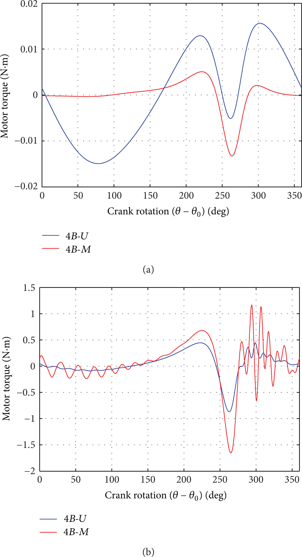
Computed motor torque at (a) 60 and (b) 600 rpm.
4. Conclusions
This paper deals with the effects of mass-balancing on the dynamic operation of a four-bar linkage, taking into account elastodynamic aspects. An experimental apparatus was arranged and tested, and a flexible multibody model of the test rig was implemented and simulated.
Experimental tests proved that the introduction of counterweights causes the mechanism dynamic operation to deteriorate even at low/medium speed. The correlation between the effects induced by counterweights and the system elastodynamic properties was clearly described. The results obtained in this work from a physical system also confirmed the most relevant conclusions drawn from the simulation activity presented in [18].
Potential issues concerning the introduction massive counterweights are known. A possible increment of both the base-transmitted forces and the motor torques is expected to a certain extent. However this study proves that the mechanism performance may worsen far more considerably than predicted. Additional mass and inertia significantly alter the system resonances, a remarkable decrement of system resonances being observed. The combined effect of higher inertia actions and lower natural frequencies causes high vibrations that affect the mechanism functioning. The resulting vibrations and torque oscillations may significantly hinder the mechanism operation and the control of the actuator.
The most relevant observations concerning the behaviour of the studied mass-balanced mechanism may be reasonably extended to generic four-bar linkages or even to other families of closed-chain mechanisms featuring slender base-attached links (e.g., the legs of parallel robots), whenever static balancing is achieved by using counterweights. Indeed, on one hand, the total mass added by counterweights is expected to be at least comparable to the total mass of the moving parts of the unbalanced linkage, thus considerably incrementing the mechanism total inertia (see, e.g., [10]). On the other hand, counterweights are generally appended to the slender links, close to the base-connecting joints, thus achieving a configuration similar to the one proposed for the investigated mechanism (see, e.g., [6]). Hence, effects analogous to those experienced for the studied four-bar linkage are expected to occur in more general cases. Therefore, according to the results of the presented contribution, mass-balancing would not seem to be a profitable strategy for closed-loop linkages, since benefits brought about by counterweights are likely to be covered by the associated drawbacks. However static balancing is still regarded as potentially advantageous for some specific applications, provided that a proper balancing strategy is implemented.
Gravity compensation of PKMs for machining operations is expected to be significantly profitable, due to their general characteristics (heavy moving platform, long set-up periods in static conditions, and low dynamics during machining path motion). The possibility of enhancing their performance (in terms of precision, energy efficiency, and safety) by means of compensation seems worthy of further investigations, but, due to the reported issues, the effects of balancing devices need to be carefully assessed. The research activity is currently focused on PKMs characterized by linear delta architecture, such as the Orthoglide [22]. In particular, the feasibility of balancing strategies which do not require counterweights is primarily investigated, even if mass-balancing may result easier to be implemented in practice (thus being potentially less expensive). Indeed, the results provided by this study proved the use of counterweights as an unsuitable solution. Elastic balancing of the Orthoglide has been analytically achieved. Its effectiveness will be verified by taking into account elastodynamic aspects to predict potential issues (such as vibrations possibly triggered by transient loads during fast movements for tool positioning).
This preliminary investigation provided the main guidelines for designing future experiments on the Orthoglide. The most relevant hint concerns the use of force transducers. The detection of base-transmitted vibrations by using accelerometers resulted as being marginally profitable in this study. Conversely, measurements of base reaction forces proved to be very effective for detecting significant effects induced by the compensation approach, and therefore they will represent the main tool for performing future analyses. However, possible strategies for enhancing the use of vibration signals will be investigated as well, due to the simple setup of vibration transducers. For instance, the use of accelerometers directly applied on the moving links may be assessed for possibly going beyond the limitations experienced in this work.
Moreover, this study suggested that the possible development of a numerical model could be profitable to better interpret the experimental data, in particular as far as the modal parameters are concerned.
Footnotes
Acknowledgment
The authors wish to thank Dr. Marco Carricato for his valuable advice in carrying out this research.