
Abstract
Laying two pipelines in one ditch is a new technology recently employed by the petroleum companies of China and has great advantages of minimizing environmental disruption as well as bringing tremendous economic and social benefits. In this study, by means of numerical simulations analyses are carried out to evaluate heating energy saving for the operation of two hot crude oil pipelines laid parallel in one ditch. Comparisons are made based on three various operating scenarios, among which the best operation is proposed. The effects of some important parameters such as the gap between the two pipelines (also called pipeline interval) and pipe length are investigated. It is found that two hot crude oil pipelines laid parallel in one ditch can dramatically save heating energy when compared with two pipelines laid, respectively, in two separate ditches.
1. Introduction
Before 2005 a common practice of oil pipeline construction was laying pipelines, respectively, in separate ditches (one ditch for one pipeline). In 2005, one ditch for two parallel pipelines (two parallel pipelines laid in one ditch) was considered and started to be adopted due to its obvious advantage of capital investment saving for pipeline construction. Therefore and since then, several hundred kilometers of crude oil pipeline and product pipeline in parallel in Western China were laid in one ditch since 2005. It was the first application of the technology of two pipelines in one ditch in the long-distance oil pipeline construction in China. The thermal effects between the crude oil pipeline and the products pipeline buried parallel in one ditch have been analyzed in [1–3]. Now with continuous development of new oil fields and huge demands on the crude oil, extension on pipeline network and increase in its throughput are in dire need, and laying two pipelines in one ditch would be an effective solution to this problem.
For crude oils with high pour point or high viscosity, heating transport is usually used to reduce the viscosity and keep pipeline operation temperature above the pour point along the pipeline for economical and safe pipelining operation [4–6]. The main shortcoming of heating transport is high energy/fuel consumption. However laying and operating two hot crude oil pipelines parallel in one ditch, due to the mutual thermal impact, may help reduce the loss of heat and thus save considerable amount of heating energy. This is of course only a qualitative estimation, and it is apparently not enough for the design and operation requirement. To precisely determine the energy saving amount by operating two pipelines in one ditch, detailed analyses should be carried out, which is the major aim and task of this paper. The results of this study will not only directly provide technical support for the pipeline construction in better way, but also give some guidelines for the operation optimization of the technology of laying two hot crude oil pipelines in one ditch.
2. Mathematical Modeling and Numerical Solution
Figure 1 shows the cross-section of the two pipelines buried in one ditch. The thermal status of the two buried hot crude oil pipelines consists of the convective heat transfer of the oil in the pipelines and the heat conduction outside the pipelines, and the latter is affected by a lot of parameters such as the air temperature, the thickness of wax deposit, the properties of soil, and the anticorrosion coating. To simplify the analyses, the following assumptions are made in the study.
The oil temperature on a fixed pipeline cross-section is assumed to be the same; in other words, the oil temperature is only the function of time and axial position.
The soil outside the pipeline is assumed as an isotropic medium, even though it is anisotropic in reality.
The thickness of the wax deposit is assumed to be constant along the pipeline.
The heat conduction of the pipeline is assumed to be two-dimensional neglecting the axial temperature drop. Since the radial temperature gradient is much greater than the axial temperature gradient, the three-dimensional heat conduction of the wax deposit, the pipe wall, and the anticorrosion coating can be simplified by using two spatial dimensions.
The thermal-influenced region of the pipeline is assumed to be within 10 meters from the axial line of the pipe. This means that beyond 10 meters from the pipeline the soil temperature is almost not affected by the pipeline. This has been demonstrated by both experimental data and numerical analysis [7]. By this simplification, a finite soil domain is generated in numerical simulation as shown in Figure 1.

Two hot crude oil pipelines laid in one ditch.
Based on the previous assumptions and simplifications, a mathematical model describing the thermal status of the buried hot oil pipeline is established as follows [8].
(1) Oil flow equations:
mass conservation equation:

momentum conservation equation:
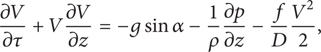
energy conservation equation:
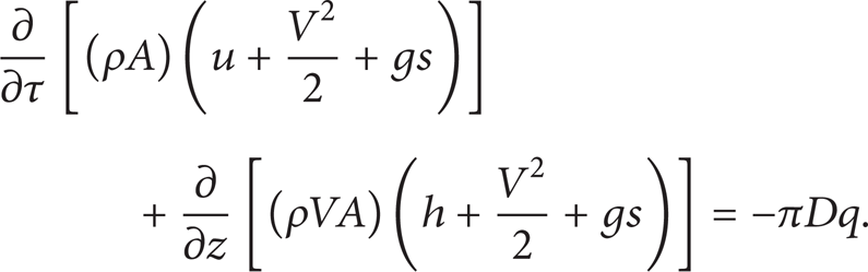
The heat transfer equation of the oil flow can be obtained from the three equations listed previously [8]:

(2) Heat transfer equations of the wax deposit, the pipe wall, and the anticorrosion coating:
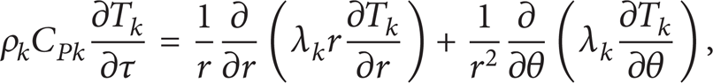
where k = 1,2, 3 stands for the wax deposit, the pipe wall, and the anticorrosion coating, respectively.
(3) Heat conduction equation of the soil

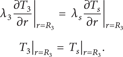
(4) Matching conditions.
The crude oil, the wax deposit, the pipe wall, and the ananticorrosion coating and the surrounding soil are highly coupled in the heat transfer process, one component greatly interacting with and affecting the others. Their coupling interactions can be described by the following equations:
(5) Boundary conditions:

The Delaunay triangulation method [9, 10] is used to generate the grids of the soil domain automatically with denser meshes near the pipelines. For simplicity, the wax deposit is not taken into account. A structural grid generation in polar coordinates is applied to the steel pipe wall and anticorrosion coating. The unstructured grids at the cross-section around the pipelines are shown as in Figure 2. Figure 3 shows the uniform grids along the pipeline. A second-order finite volume method is used to discretize the heat conductive equations of soil, pipe wall, and anticorrosion coating. The governing equations in soil domains and the pipeline are discretized in different ways and coupled along their interfaces in an iterative procedure. An implicit method is used for time discretization. The discretized equations are solved by a Gauss-Seidel method.
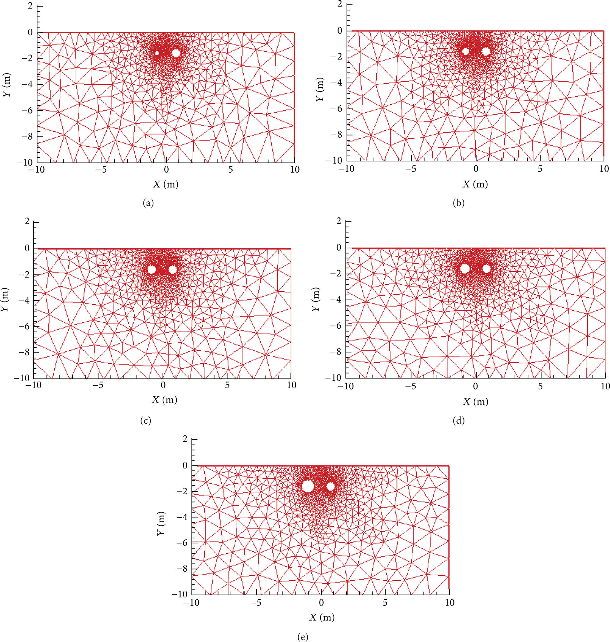
The unstructured grids of the soil.
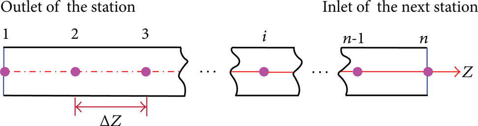
Grids of the pipeline.
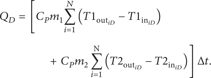
For simplicity, in the simulation, it is assumed that the double-pipeline system has N heating stations with the same station spacings and both pipelines transport the same crude oil. The inlet temperature of each heating station is Tin while the outlet temperature of each station after heating is Tout. Note that according to the China's Operating Rules for Pipelines Delivering Waxy Oil with Heating, Tin should be not lower than the pour point of the crude T P . Then for the double-pipeline system, the heating energy can be calculated as
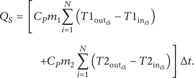
For the two independent single-pipeline system the consumed heating energy is
Then the heating energy saving rate of the double-pipeline system can be obtained as follows:
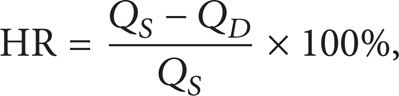
where Q is the energy or heat quantity absorption of the crude oil, J; m is the mass flow rate in the pipeline, kg/s; andC P is heat capacity of the crude oil, J/ (kg·°C). The heat capacity of the crude oil in the calculations is set as 2100 J/ (kg·°C). Δt is the operating time, and s. HR is energy saving rate. The subscripts s and D stand for single-pipeline system and double-pipeline system, respectively, and subscripts 1 and 2 represent pipeline 1 and pipeline 2 (namely P-1 and P-2), respectively, as shown in Figure 1. For both single-pipeline system and double-pipeline system, Tin at the first heating station is assumed to be equal to the pour point.
3. Computations and Economy Analysis
For single-pipeline system, it is assumed that Tout1 = T1 and Tout2 = T2 for both pipeline 1 and pipeline 2, and all inlet temperatures at stations are equal to the pour point, that is,Tin1 = Tin2 = T P . It can be expected that in the double-pipeline system, if the outlet temperatures of the two pipelines are set the same as those of the corresponding single-pipeline system, due to the mutual heating impact, the inlet temperatures of both two pipelines in the double-pipeline system would be most likely higher than that of single-pipeline system; hence, compared with single-pipeline system, the outlet temperatures in double-pipeline system could be lowered down less or more with the inlet temperatures still maintained above the pour point to meet the operating rules.
Since the outlet temperature is a key factor determining heating energy consumption, optimization could be made on this parameter to reduce the energy consumption. In this study, three operating scenarios are presented to analyze the economy of different operating conditions in the double-pipeline system as follows. (a) The outlet temperature of P-1 is set the same as that of the single-pipeline system whereas the outlet temperature of P-2 is tentatively and gradually reduced until the inlet temperatures of the P-1 and P-2 drop down no more than pour point. (b) The outlet temperature of P-2 is set the same as that of the single-pipeline system whereas the outlet temperature of P-1 is tentatively and gradually reduced until the inlet temperatures of the P-1 and P-2 drop down no more than pour point. (c) Both outlet temperatures of P-1 and P-2 in the double-pipeline are put in gradual decrease until their inlet temperatures drop down to just above the pour point.
Calculations are first made for five typical cases as shown in Table 1, and some other important computation parameters are listed in the following. The heating station spacings are all 120 km: The gap between two pipelines is 0.9 m and constant. The mean flow velocity in the pipes is 1.5 m/s. The pour point of the waxy crude oil is 30°C. The thermal conductivity of the soil is 1.4 W/(m·°C) and the soil temperature at the buried depth is 1.6°C. The thickness of anticorrosion coating is 4 mm.
The outer and inner diameters of pipes.

Table 2 shows the outlet and inlet temperatures for the three operating scenarios presented previously of different double-pipeline systems with the temperatures of single-pipeline system included. It can be seen that for the single-pipeline system, to maintain the inlet temperature not lower than pour point, the highest required outlet temperature is 81.95°C and the lowest is 38.07°C; the smaller the pipe, the higher the outlet temperature required. This is because at the same mean velocity, the smaller the pipeline, the lower flow rate. As known, lower flow rate contains lower heat capacity which will lead to a quicker temperature drop; hence smaller pipeline needs higher outlet temperature to maintain the same inlet temperature than larger pipeline does. Table 2 indicates that under scenarios 1 and 2, by only adjusting one pipeline's outlet temperature, the pipeline being adjusted reaches the lowest allowable inlet temperature, that is, pour point, and the other pipeline still holds a higher inlet temperature. In scenario 3, the two pipelines' outlet temperatures are adjusted simultaneously to make both pipelines hold lowest temperatures inlet. To achieve this, both outlet temperatures have to be reduced greatly.
Outlet and inlet temperatures when the station spacing is 120 km.
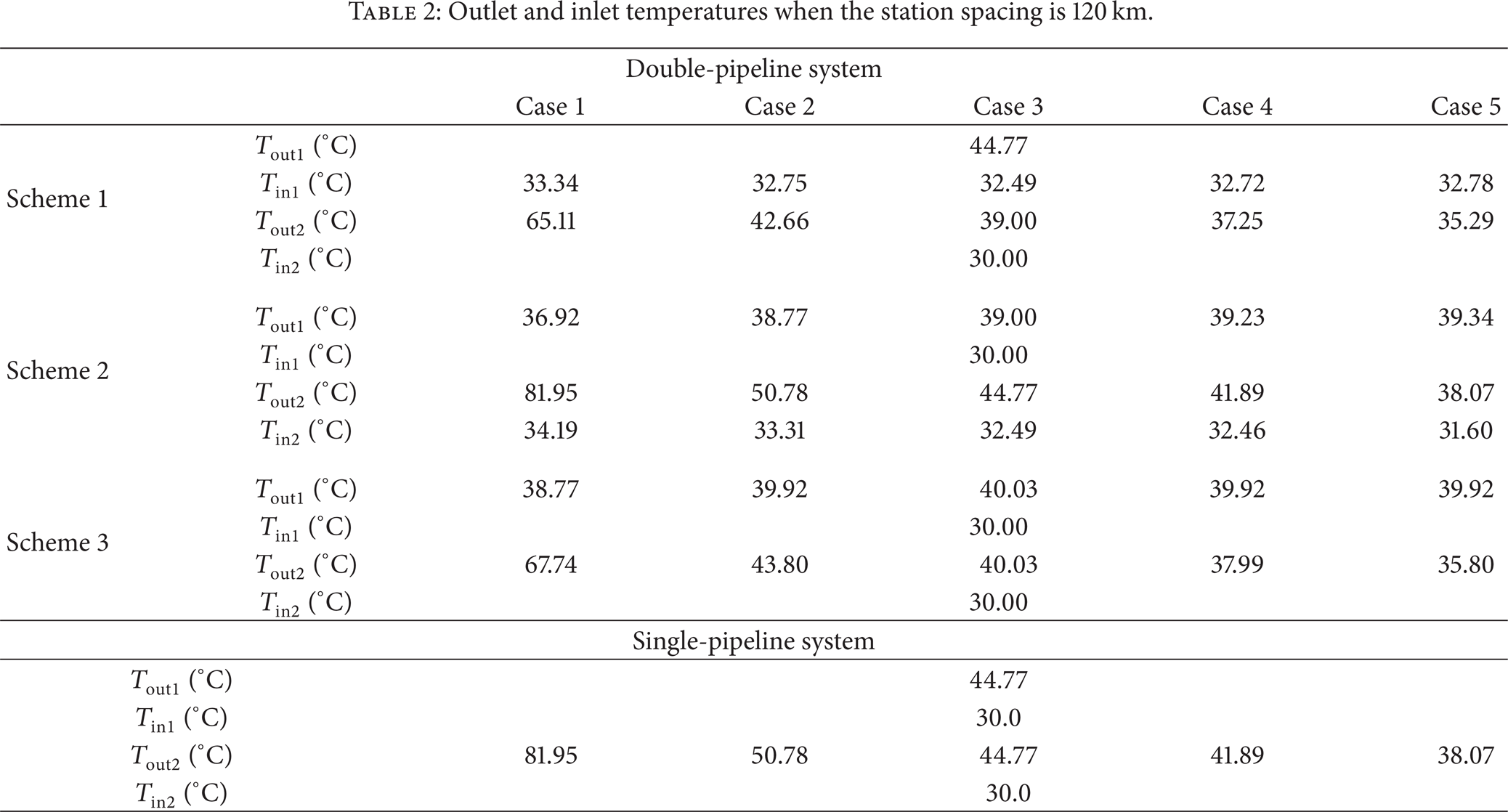
Figure 4 shows the energy saving rates of double-pipeline systems under different operating scenarios or scenarios and with different numbers of heating stations. Figure 4 also shows that scenario 3 can save 33.7%, 33.2%, 32.0%, 32.8%, and 30.4% heating energy for cases 1–5, respectively, regardless of the number of heating stations. In comparison, for the other two scenarios, energy saving rate increases with the increase of the number of heating station and when the heating stations are more than 10, the energy saving rate reaches maximum value and is then kept constant. Figure 4 further indicates that scenario 3 can save much more energy than the other two scenarios. This indicates that when the inlet temperatures of double-pipeline system are maintained closer to the pout point, the lower outlet temperatures are required when compared with single-pipeline system, hence the less the heating energy consumption is required resulted in saving of heating fuel. Scenario 3 consumes the least energy because generally speaking lower outlet temperatures will reduce the temperature difference between the crude oil and soil temperature, and thus reduce heat loss compared with the other scenairos. Therefore, operating scenario 3 is the best and recommended.
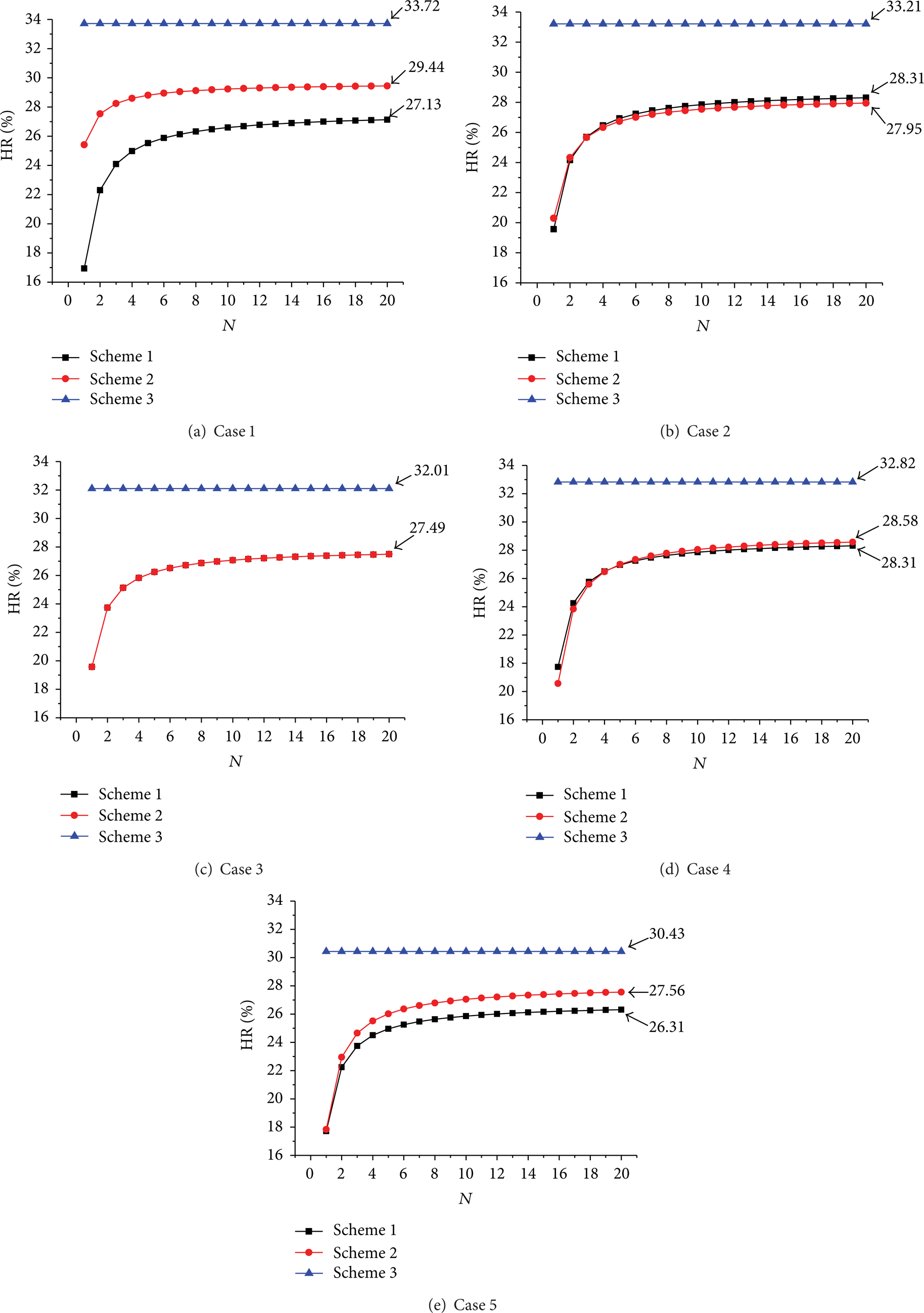
The energy saving rate for different cases when the station spacing is 120 km.
One question may be raised: why the heating energy saving rate is independent of the number of heating station under scenario 3. This is because for operation scenario 3 station all inlet temperatures are the same and so are all outlet temperatures. From (9) to (11) that the energy saving ratio for scenario 3 can be determined as follow:

Equation (12) demonstrates that energy saving rate is independent of heating station as it does not involve the term representing the number of heat stations. As (12) is independent of the number of heating stations, the subscript i is omitted.
For the other scenarios, from (9) to (11), the energy saving rates can be determined in a similar way:

In the previous equation, note that from heating station 2 to N, the inlet and outlet temperatures are identical, and the subscript i is omitted. Equation (13) shows that for the other scenarios the energy saving rate is related to station number N. It can be seen clearly that its effect becomes weaker with the increase of N and the energy saving rate gradually approaches to the maximum value:

In one word, (13) explains why for scenarios 1 and 2 heating energy saving rate increases with the increase of the number of heating stations and approaches to the maximum value.
With the improvement and development of the construction technology in pipeline industry, there is a tendency to save the construction cost by extending the station spacing and thus reducing the number of heating stations. When the spacing is extended to 240 km, much higher outlet temperatures are required to maintain the inlet temperature above a certain point, say pour point as required, and the temperature difference between different scenarios becomes greater. The energy saving rate in the double-pipeline systems for greater station spacing is shown in Figure 5. For case 1 the energy saving rate is not shown. This is because for such a case the outlet temperature of the smaller pipeline has to be higher than 100°C which is impractical in reality. It can be seen that the energy saving rate is greater than that of smaller station spacing; the advantages of the new technology laying two pipelines in a ditch are more significant.
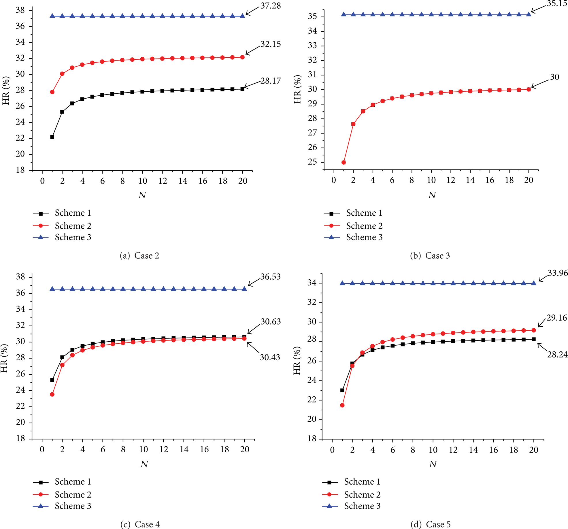
The energy saving rate for different cases when the station spacing is 240 km.
Apparently pipeline gap or interval imposes the most important effect on energy saving. Table 3 shows the heating energy saving rates for scenario 3 at different pipeline intervals with other calculation parameters fixed. As indicated, the energy saving rate is about 20% with the pipeline interval at 1.8 m and can be as high as about 37% with the pipeline interval reduced to 0.6 m. For all the cases, the smaller the pipeline interval, the greater the energy saving rate. From the view of heat transfer, the smaller the interval between the two crude oil pipelines, the lower the outlet temperatures will be needed which resulted in less heating cost; therefore reducing the interval would be considered a priority in pipeline construction. However, it should be noted that besides the matter of heat transfer, in actual pipeline construction still many other factors have to be taken into consideration to determine pipeline intervals. The determination of the optimal interval should involve thermal condition of operation and conveniences for construction and reparation and all factors have to be well considered and balanced.
Effect of pipeline interval on heat energy saving rate (%).
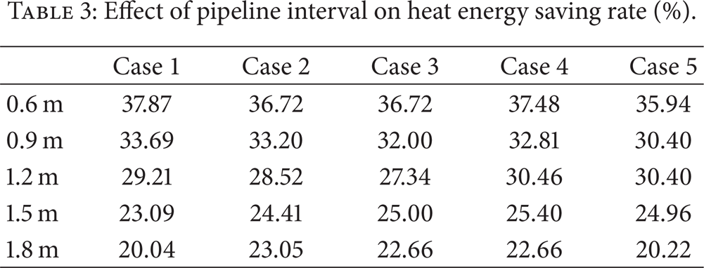
Figure 6 shows the temperature field (contours) at the inlet cross-section for scenario 3. As showed, generally the soil temperatures for a double-pipeline system are higher than those of a single-pipeline system, which benefits pipelining waxy-crude oil with high pour point. This is because the region with lowest temperature near the inlet of heating station is usually the most dangerous region during normal operation and especially after the pipeline shutdown. For the double-pipeline system, the higher soil temperature near the entrance of the next heating station can reduce the heat loss of crude oil and consequently enhance the operation safety.

Comparison of the inlet temperature contours.
4. Conclusions
In this paper heating energy saving evaluations in the operation of two hot crude oil pipelines laid in one ditch as compared with the single-pipeline system are performed. In the calculations a Delaunay triangulation method is used to generate the grids of the soil domain automatically with denser meshes near the pipelines. A structural grid generation in polar coordinates is applied to the steel pipe wall and anticorrosion coating. A finite volume method combined with a finite difference scheme is used to discretize the governing equations. The discretized equations are solved by a Gauss-Seidel method. The thermal impact between two hot crude oil pipelines laid in one ditch under three operating scenarios is numerically analyzed. It is shown that the operating scenario in which both the inlet temperatures reach the allowed lowest temperatures (pour point) can save the greatest deal of energy. With the increase of the pipeline interval, the thermal impact between double-pipelines becomes less, which results in the decrease of the energy saving. When the spacing between two heating stations extends, the energy saving increases. The energy saving rate is about 20% with the pipeline interval at 1.8 m and can be as high as about 37% with the pipeline interval reduced to 0.6 m. In addition to the advantage of energy saving, laying two hot pipelines in one ditch can also enhance the operation safety according to the result of the study.
Footnotes
Nomenclature
Acknowledgment
The study is supported by the National Science Foundation of China (no. 51176204 and no. 51206186), and the Science Foundation of China University of Petroleum, Beijing (no. 2462011LLYJ33, no. 2462011LLYJ55, no. 2462012KYJJ0403, and no. 2462012KYJJ0404).