
Abstract
This paper presents a new kind of shock absorber, hydraulic electromagnetic shock absorber (HESA), which can not only isolate vibration but also recover energy from vibration of vehicles. The energy recovery scheme is put forward, and the HESA prototype as well as the bench is trial manufactured. The damping characteristic of the HESA prototype is tested, and its performance is good under low cracking pressure and small excitation amplitude without taking the requirement that damping force in compression stroke is greater than that in extension stroke into account. The energy-regenerative characteristic of the HESA prototype is investigated, and it can recover energy about 200 watts in 10 Hz-3 mm excitation. However, the energy recovery efficiency is only 16.6%, and the rectifying efficiency of the hydraulic rectifier decreases with the excitation frequency increase, which eventually leads to a reduction in energy recovery efficiency. The linear loss of oil is analyzed theoretically, and the wasted power of pipeline is found to account for 1/3 of the total power. It can be seen from the mathematical model of linear loss that this energy loss can be decreased effectively by increasing the inner diameter of pipeline.
1. Introduction
With the aggravation of energy loss and air pollution (e.g., the endless haze in Beijing, China), energy saving and emission reduction have become hot topics in the country or even around the world. Studies about energy recovery, such as heat recovery [1–3], bioenergy recovery [4, 5] and vibration energy recovery [6–8], have been supported extensively by numerous countries and their government in the world.
Energy recovery from shock absorber is a kind of method recovering energy from the vibration, and the relevant research has been developed since the early 1990s. The early programs of energy recovery were proposed by Suda and Shiiba [6] and Okada and Harada [7], and their programs were both with linear DC generator. However, the linear motor was generally very expensive, and the efficiency of the linear motor was much lower than that of the rotary one as validated by Gupta et al. [9]. Nakano and Suda [10] found that rotating electromagnetic dampers had the advantage of mechanical amplification, and they developed extra dynamic elements in series with the rotating damper to improve the vehicle dynamics. Then, Graves et al. [11] developed their own energy-regenerative shock absorber using rotary DC motor and ball screw mechanism, while the results suggested that some parts still needed to be improved. Li et al. [12] tested their energy-regenerative shock absorber based on rack and pinion mechanism, and their program was proved to be feasible by both simulation and test results. But the damping characteristic and energy-regenerative characteristic of their program still needed to be improved. The two mechanical programs have the same shortcomings, that is, the backlash of mechanical transmission is inevitable. The backlash seriously affects the reliability and durability of the energy recovery system, because gear cracks even tooth breakage may happen due to serious road impact. To obtain higher efficiency and better reliability and durability, this paper tries to develop another program with rotary motor-HESA [8, 13].
This paper is organized in the following manner. Section 2 describes the energy recovery scheme and builds the HESA prototype and the corresponding test bench. The damping characteristic and energy-regenerative characteristic are presented in Sections 3 and 4, respectively. In Section 5, high-frequency response characteristics of the HESA prototype are studied. According to the above work, the energy loss analysis is carried out in Section 6. In the end, conclusions from the analysis and experiments are provided in Section 7.
2. Working and Trial Manufacture of HESA
2.1. The Schematicsof HESA
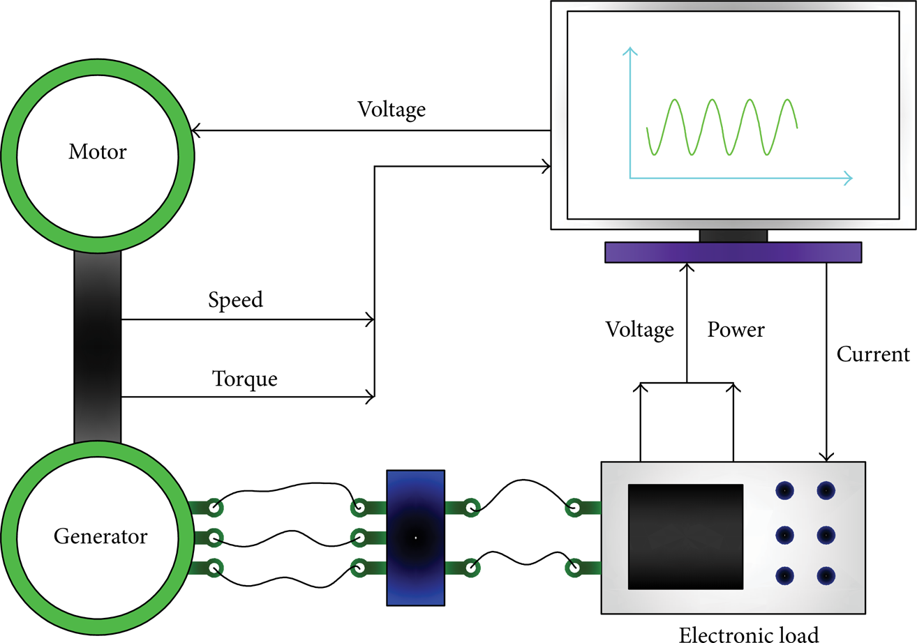
HESA is a new kind of shock absorber, which can not only isolate vibration but also recovery part of the energy dissipated by heat. Its working principle is shown in Figure 1. It can be seen that the HESA is composed of hydraulic cylinder, hydraulic rectifier, accumulators, hydraulic motor, generator, pipelines, and so on. The working principle of hydraulic rectifier is similar to Wheatstone bridge. The piston of the hydraulic cylinder is driven to reciprocate under external stimulus, and the high-pressure oil flows into the hydraulic rectifier. So the oil flows out of the hydraulic rectifier from the specified export in the compression stroke or extension stroke and then flows through the accumulator for weakening fluctuation, which drives the hydraulic motor to generate electricity. The electric energy can charge a battery or be supplied to vehicles directly [13]. In this paper, the generator is connected to the electronic load for study.
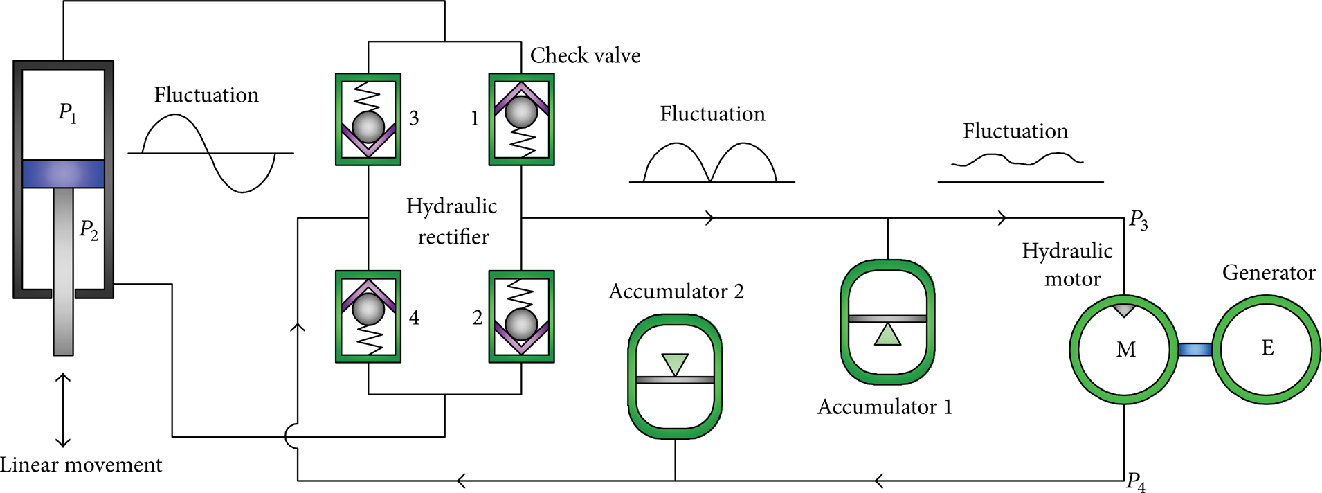
Schematics of the HESA.
2.2. Trial Manufacture of HESA and the Bench
The HESA prototype is manufactured according to its working principle, and the test bench is built in accordance with the standard QC/T 545-1999 [14] as shown in Figure 2. Hydraulic cylinder, hydraulic rectifier, and accumulator 2 are integrated into the HESA. Accumulator 1, hydraulic motor, generator, and its connecting pipes are arranged in the panel on top of the bench. P1 and P2 represent the pressure of upper and lower chamber of the hydraulic cylinder, respectively. P3 and P4 represent the pressure of inlet and outlet of the hydraulic motor, respectively. During the test, if the hydraulic circuit contains a lot of air or entrapped gas, the analysis of damping force may become very difficult, which may degrade the energy-regenerative performance. If the connecting pipes or components leak oil, the hydraulic pressure of the system may reduce gradually, resulting in greater possibility of cavitation, which may create numerous pockets of oil bubble throughout the oil. A small increase of pressure can easily turn the oil bubble back into liquid, with a severe slam shock, causing bad noise and possible damage to the damper internals [15]. Therefore, we have to check the pressure drop of the hydraulic circuit before and after each test and install exhaust valve in the circuit.

The HESA prototype and its test bench.
3. Damping Characteristic
The basic function of a shock absorber is to isolate vibration. As HESA is a kind of shock absorber, we need to pay great attention to its characteristic of vibration isolation. The arrangement of experiment is as follows. A sine wave excitation in displacement with 1.67 Hz in frequency is executed on the HESA, and the displacement is increased gradually until the damping force reaches the limit of the force sensor. Because of the cracking pressure of accumulator 1 greatly affecting the characteristic of HESA, we test the characteristic of HESA with two accumulators, 5 bars and 20 bar sin cracking pressure. The reason of selecting 5 bars, and 20 bars as the cracking pressure is that the pressure in gas chamber of twin-tube shock absorber is always between 4 and 6 bars and of monotube is always between 15 and 40 bars.
Figure 3 shows the force-displacement loop when the cracking pressure of accumulator 1 is 20 bars. The amplitude of the excitation is 12.5 mm, 20 mm, 25 mm, 30 mm, and 37.5 mm respectively. From the force-displacement loop we can get the following.
The force-displacement loop is asymmetric on y-axis, and the damping forces on y-axis have a big difference, which indicates that larger damping force is needed to circulate the oil when changing direction of the damping force under larger accumulator opening pressure.
A mutation of damping force occurs every time when it changes direction. Mounting clearance between the HESA prototype and the test bench is inevitable, so the opening and response time of the spool of one-way valve and accumulator will both enhance the damping force sharply when its direction changes.
The damping force is greater in compression stroke than that in extension stroke.
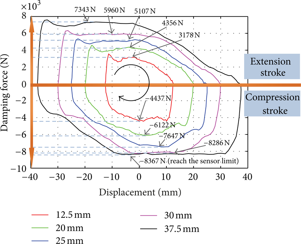
Force-displacement loop (20 bars).
Figure 4 shows the force-displacement loop as the cracking pressure is 5 bars. The amplitude of the excitation is 12.5 mm, 20 mm, 25 mm, 37.5 mm, and 50 mm, respectively. Compared with the accumulator with 20 bars in cracking pressure, the accumulator with 5 bars has the same problems in force mutations and damping force asymmetry. Under the same excitation, systematic damping force with accumulator with 5 bars is smaller. What is more important, the force-displacement loop is approximately symmetrical on y-axis, that is, the accumulator with opening pressure of 5 bars has little impact on the systematic damping force when ensuring the high-line pressure at the entry end of the motor stable, which means that the speed characteristic of the shock absorber has less hysteresis. Particulary when the excitation amplitude is less than 25 mm, the force-displacement loop is almost symmetrical on y-axis.
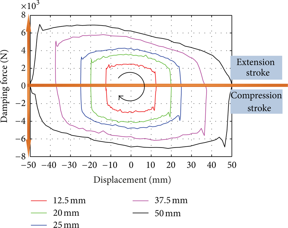
Force-displacement loop (5 bars).
It should be mentioned that the force mutations shown in Figures 3 and 4 will not appear when the HESA is mounted in a car. In that case, although the requirement that greater damping force in extension stroke than compression stroke is easy to achieve, it is difficult to get the indicator diagram about the y-axis symmetry.
4. Energy-Regenerative Characteristic
Energy recovery is the most important characteristic of HESA, which is different from other shock absorbers. Therefore, we test the energy-regenerative characteristic of the HESA prototype.
The HESA is given a sinusoidal displacement excitation, where the frequency is f = 10 Hz and the peak amplitude is A = 3 mm. By controlling the electronic load, the current is stabilized at 20 amp, 30 amp, and 40 amp, respectively as shown in Figure 5, and the corresponding average voltage and power are shown in Table 1. From Figure 5 we can get that when the current is 30 amp or 40 amp, the energy recovery power is about 200 watts, while the power is more fluctuant in 40 amp than that in 30 amp.
Voltage and power at different currents.


The voltage and energy-regenerative power at different currents.
Table 1 shows the recovered energy at different load currents. And all of the energy is input by the excitation source. The input power is the area of the damping loop, and it can be obtained by

where T is the period, F(t) is the damping force, and x is the displacement of absorber, which can be expressed as:

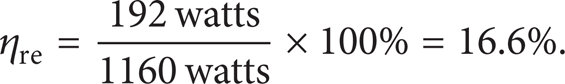
When the current is set to 30 amp, from (1), (2), and the corresponding collected damping force, we can calculate the input power Pall = 1160 watts. In this case, the energy-regenerative rate is
The reasons for lowenergy-regenerative rate are considered as follows.
In the hydraulic circuit, the minimum inner diameter of pipeline is only 6 mm, and there are many local blocks in the flow of oil, resulting in the heavy linear and local loss of oil.
The inner friction of the HESA prototype between the piston and the cylinder wall dissipates the system energy.
The pressure drop of the check valves in hydraulic rectifier dissipates the system energy.
The generator is transformed from vehicle motor, so the amplitude of its power generation voltage is limited to approximately 13.6 volts. More important, as a generator, its efficiency in specific rotational speed may not be high.
The hydraulic rectifier is inefficient in high-frequency excitation.
Of the above five reasons, the first three can be improved through transforming or remanufacturing the bench and the principle prototype. As to the fourth reason, it needs to find out the most common speed range of the hydraulic motor, which is mainly decided by the size of hydraulic cylinder, the tire, and the actual road spectrum. Then, suitable generator which has higher efficiency should be selected in corresponding speed range. Moreover, the load protection should also be set up to prevent generator and motor damage. However, the last reason is difficult to be settled, because the presence of hydraulic rectifier affects not only the damping characteristic of HESA but also the energy-regenerative characteristic of HESA. And further work is required to deal with the problem.
5. The Influence of Hydraulic Rectifier
According to the above work, the presence of the hydraulic rectifier is considered to be the reason of poor performance in high-frequency excitation. However, the hydraulic rectifier cannot be removed. As previously mentioned, just due to the presence of hydraulic rectifier, the hydraulic motor is driven from one side no matter the shock absorber is in the compression stroke or extension stroke. If the hydraulic rectifier is removed, the oil will drive the motor from two sides, and the motor will change its rotational direction twice in each excitation cycle. This phenomenon seriously affects the efficiency of the motor, and the motor even stops rotating during high-frequency excitation because of the inertia of the rotating parts, the backlash, and friction.
The hydraulic rectifier is composed of four check valves, and effective rectifying depends on the timely opening and closing of the check valve. Assuming the upper chamber of the shock absorber is the high-pressure chamber at a moment, the check valve should be closed quickly when the upper chamber changes from high-pressure chamber into low-pressure chamber. However, the check valve would not close timely due to the presence of resilient elements of the check valve, the mass of the moving part, and the friction between the piston and the cylinder wall. Then some oil would flow back to the upper chamber when its pressure drops to a pressure lower than that at the outlet of the hydraulic rectifier. Actually, this phenomenon is internal leakage, and the reflux fluid is not acting but directly flows from the high-pressure chamber to the low-pressure chamber. Given the HESA prototype a sinusoidal displacement excitation with the peak amplitude of A = 1.9 mm and the frequency of f = 10 Hz, the packing pressure of the system can be calculated as about 5 bars, assuming the inner diameter of the cylinder chambers is R = 50 mm, the diameter of the piston rod is R r = 20 mm, the displacement of the hydraulic motor is q = 5 cc/rev, the nominal volume of the accumulator is 0.16 L, and its cracking pressure is 20 bars.
Figure 6 shows the measured pressure of P1, P2, P3, and P4. It can be seen that the inlet pressure of the motor P3 fluctuates widely while the outlet pressure of motor P4 is relatively stable. And the pressure of P3 is influenced greatly by the nominal volume and the cracking pressure of accumulator 1.

Pressure fluctuations of P1, P2, P3 and P4.
The rectifying efficiency of hydraulic rectifier can be evaluated by the ratio of actual speed and theoretical speed of the motor. The average rotational tested speed of the motor is about 1100 rev/min, and the theoretical speed can be calculated as follows.
The theoretical flow of the hydraulic cylinder in one cycle is

Correspondingly, the volume flow can be

The working volume of the hydraulic motor is q c = 5.5 cc/rev. According to the data provided by the motor supplier, the volumetric efficiency is approximately η v = 0.88 when the rotational speed meets n ∈ [200, 4000] rev/min. So the theoretical average speed of the hydraulic motor is

From (4)–(6), we can get n0 = 1318 rev/min. So the rectifying efficiency of hydraulic rectifier at 10 Hz excitation will be

Similarly, we can get the rectifying efficiency of hydraulic rectifier at different excitations as shown in Figure 7. From Figure 7, we can see that the rectifying efficiency of the hydraulic rectifier decreases with the excitation frequency increase, and the rectifying efficiency declines acceleratedly when the excitation frequency reaches 10 Hz, which eventually leads to the reduction of energy recovery efficiency. So check valve with larger flow and faster response is needed, that is to say, efficient hydraulic rectifier is needed.

Rectifying efficiency of the hydraulic rectifier at different excitation frequencies.
6. Energy Loss Analysis
In the HESA prototype, energy loss mainly includes loss on pipeline, hydraulic rectifier, hydraulic motor, and generator, in which loss on pipeline involves linear and local loss. According to Darcy formula, the linear loss on the pipeline is

where λ is the linear loss coefficient, L is the length of the pipeline, v c is the flow rate of the oil in pipeline, g is the acceleration of gravity, and d is the diameter of pipeline.
Reynolds number is

where υ v is the kinematic viscosity. In the compression stroke, the flow rate of oil in pipeline is

where D is the inner diameter of hydraulic cylinder. Under the same excitation amplitude, due to the presence of piston rod, the high-pressure oil flow in the compression stroke is larger than that in the extension stroke. If υ v is 100 mm2/s, then, under the 10 Hz-3 mm excitation, the maximum of Reynolds number is

For the circular tube, when Reynolds number is less than 2300, the oil flow is in the laminar flow state, so the linear loss coefficient is

From (8), (9), and (12), the linear pressure loss equation of pipeline is
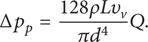
Figure 8 is the dependence of the sinusoidal displacement of absorber excitation source on time. Here, we choose one cycle of the displacement excitation (e.g., the carmine displacement curve) for study. By neglecting the real-time effect of energy accumulator on system pipeline flow and assuming the pipeline flow is the same to the output high-pressure oil flow in the hydraulic cylinder, it can be obtained that

where D r is the diameter of piston rod, Q c and Q e is the pipeline flow in the compression stroke and extension stroke, respectively.

Displacement excitation.
Assuming the efficiencies of the hydraulic rectifier in compression stroke extension stroke are both 83.5%, and then the linear power loss is
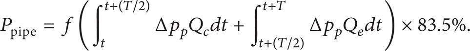
After integration, it can be gotten that

By substituting the parameters of the HESA in Table 2 for (16), the loss power of the pipeline can be obtained as

Parameters of the HESA.

Thus, the ratio of linear power loss to the total input power is

From (16) and (18), it can be seen that in the HESA prototype, linear loss along the hydraulic pipeline accounts for 1/3 of the total energy. Linear loss is inversely proportional to the fourth power of pipeline diameter, so increasing the pipeline diameter can decrease the linear loss of the pipeline effectively and raise the efficiency of energy recovery.
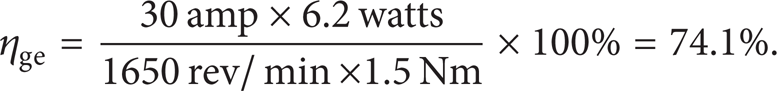
Efficiency of the generator was tested by the program shown in Figure 9. By controlling the voltage of electric motor and the current of electronic load, the generator output current can be stabilized at about 30 amp. The output torque of electric motor and the electronic load voltage were gotten under motor speed as shown in Figure 10. From Figure 10 we can get that, the average output voltage of electronic load is 6.4 volts, and the average output torque of motor is 1.50 Nm while the rotational speed of generator is about 1650 rev/min. Thus, the energy recovery ratio is the ratio of energy input and output:
Schematics of efficiency test for generator.

Generator efficiency curve.
Within the speed range of 200–4000, the volume efficiency of motor is about 88% and the mechanical efficiency is 0.82–0.9, as supported by motor supplier. Simplifying the mechanical efficiency and setting the value as 0.86, then the power delivered to the hydraulic motor is

And thus, the ratio of loss energy of motor and generator to the total energy is

According to (3), (7), (18), and (21), the energy distribution of the HESA prototype can be illustrated as shown in Figure 11, from which it can be seen that the linear loss (33.7%) is the largest, followed by the generator and hydraulic motor loss (21.1%) and then the hydraulic rectifier loss (16.5%), while oil local losses and others are the least (12.1%). So the first three loss should be taken into consideration to raise the recovered energy efficiency of the HESA, especially the oil linear loss, which can be reduced effectively and easily through promoting the pipeline design of the prototype.

Energy distribution of the HESA prototype.
7. Conclusions
In this paper, the prototype of HESA is trial manufactured and the corresponding test bench is also built. The damping characteristic and energy-regenerative characteristic of the HESA are investigated, and the energy distribution of the HESA is analyzed. The following conclusions can be drawn from this study.
When the excitation amplitude is lower than 25 mm and the cracking pressure of accumulator 1 is 5 bars, the indicator diagram of the HESA is almost symmetric on y-axis, and the speed characteristics hysteresis is small although the requirement that damping force greater in compression stroke than extension stroke has not been taken into account.
The energy-regenerative characteristic of the HESA prototype is greatly influenced by the hydraulic rectifier. Firstly, pressure drop of the check valve in the hydraulic rectifier dissipates the system energy. Secondly, the rectifying efficiency of the hydraulic rectifier decreases with the excitation frequency increase because of the time delay of the opening and closing of the check valves, which eventually leads to a reduction in energy recovery efficiency.
The linear loss of oil accounts for the largest share of the energy distribution of the HESA prototype, and it can be decreased effectively by increasing the inner diameter of pipe line based on our proposed mathematical model of linear loss.
Footnotes
Acknowledgments
The authors gratefully acknowledge the National Natural Science Foundation of China by 2011 (Project no. 51075312) and Wanxiang Group Corporation Technology Center.