
Abstract
A mixed volume and boundary integral equation method (mixed VIEM-BIEM) is used to calculate the plane elastostatic field in an unbounded isotropic elastic medium containing multiple isotropic/orthotropic elliptical inclusions of arbitrary orientation and a circular/elliptical void subjected to remote loading. In order to investigate the influence of a circular/elliptical void on the interfacial stress field, a detailed analysis of the stress field at the interface between the matrix and the central isotropic/orthotropic inclusion is carried out for the square packing of eight inclusions and one void, taking into account different values for the orientation angles and concentration of the inclusions. The mixed method is shown to be very accurate and effective for investigating the local stresses in composites containing isotropic/anisotropic fibers and a circular/elliptical void.
1. Introduction
A micrograph of the cross section of a phosphate glass fiber/polymer composite is shown in Figure 1 [1]. Figure 1 indicates that the fibers are close to ellipses, and the major axis of the elliptical fibers is not aligned in any one direction. If voids are caused by manufacturing and/or service induced defects, they may have a significant effect on the local stresses in the composite.

Phosphate glass fiber/polymer composite cross section [1]. Used with permission from Journal of Materials Science: Materials in Medicine.
A number of analytical techniques are available for solving stress analysis of inclusion problems when the geometry of the inclusions is simple (i.e., cylindrical, spherical, or ellipsoidal) and when they are well separated [2–4]. However, these approaches cannot be applied to more general problems where the inclusions are of arbitrary shape and their concentration is high. Thus, the stress analysis of heterogeneous solids often requires the use of numerical techniques based on the finite element method (FEM) or boundary element method (BIEM). Unfortunately, both methods encounter limitations in dealing with problems involving infinite media or multiple inclusions. However, it has been demonstrated that a recently developed numerical method based on a volume integral formulation can overcome such difficulties in solving a large class of inclusion problems [5–10]. One advantage of the volume integral equation method (VIEM) over the boundary integral equation method (BIEM) is that it does not require the use of Green's functions for both the matrix and the inclusions [11, 12]. In addition, the VIEM is not sensitive to the geometry or concentration of the inclusions. Moreover, in contrast to the finite element method (FEM), where the full domain needs to be discretized, the VIEM requires discretization of the inclusions only [13, 14].
However, the VIEM cannot be directly applied to problems involving voids since the field quantities are undefined in the domain of the integral equation. By contrast, problems involving voids can be most effectively solved using the BIEM. However, if the material contains a combination of elliptical inclusions and a circular/elliptical void, it is most advantageous to apply a combination of the two methods [7–9].
Therefore, in this paper, the mixed volume and boundary integral equation method (mixed VIEM-BIEM) developed by Lee et al. [7–9] is used to calculate the elastic field in composites consisting of an isotropic matrix containing multiple isotropic/anisotropic elliptical inclusions and a circular/elliptical void subjected to remote uniaxial tension. The elliptical inclusions are assumed to have different orientations relative to the loading direction. In order to investigate the influence of a circular/elliptical void on the interfacial stress field, a detailed analysis of the stress field at the interface between the matrix and the central isotropic/orthotropic inclusion is carried out for square packing of eight inclusions and one void, taking into account different values for the orientation angles and concentration of the inclusions. It should be noted that, in the previous mentioned papers [7–9], the inclusions were circles composed of isotropic or orthotropic materials. It is demonstrated that the mixed volume and boundary integral equation method is very accurate and effective in calculating the local stresses for these types of composites.
2. Volume Integral Equation Method
The geometry of the general elastostatic problem considered here is shown in Figure 2 where an unbounded isotropic elastic solid containing a number of isotropic or anisotropic inclusions of arbitrary shape is subjected to prescribed loading at infinity. The symbol

Geometry of the general elastostatic problem.
Let u
m
°(

where the integral is over the domain occupied by the inclusions,
If
3. Mixed Volume and Boundary Integral Equation Method
In this section a mixed volume and boundary integral equation method is introduced as an effective numerical scheme for the solution of elastostatic problems in an unbounded isotropic matrix containing isotropic or anisotropic elliptical inclusions of arbitrary orientation and voids subjected to remote loading. The VIEM is effective for problems with isotropic or anisotropic inclusions due to the fact that it is not necessary to apply continuity conditions at each interface, and only the Green's function for the unbounded isotropic matrix is needed in the formulation. However, the VIEM cannot be directly applied to problems involving voids, since the field quantities are undefined in the domain of the integral equation. Problems involving voids can be most effectively solved using the BIEM. However, if the material contains a combination of voids and inclusions, it is most advantageous to apply a combination of the two methods. The mixed volume and boundary integral equation for the problem shown in Figure 3 can be expressed in the following form [7, 9]

where V is the volume of the inclusion, S is the surface of the void, and
(a) Multiple orthotropic elliptical inclusions and an elliptical void and (b) multiple isotropic elliptical inclusions and a circular void in an unbounded isotropic matrix under uniform remote tensile loading.
4. Elastostatic Problems for Multiple Elliptical Inclusions of Arbitrary Orientation and a Void
To investigate the influence of a circular/elliptical void on the interfacial stress field, we consider plane strain problems for multiple isotropic or orthotropic elliptical inclusions of arbitrary orientation and a circular/elliptical void in an unbounded isotropic matrix under uniform remote tensile loading, σ xx °, as shown in Figure 3. For elliptical cylindrical inclusions or a void, when the major axis coincides with the x-axis at an inclined angle α = 0°, the aspect ratio for each elliptical inclusion or void is assumed to be 0.5 (see Figure 3). α is defined as the orientation angle of each elliptical inclusion or void measured counterclockwise from the x-axis.
A detailed analysis of the stress field at the interface between the matrix and the central inclusion is carried out for the square packing of eight isotropic/orthotropic inclusions and one void in the unbounded matrix. The fiber volume fraction, defined as that of the circular inclusions (indicated by the dotted lines) circumscribing the elliptical inclusions, is 0.3 and 0.5, respectively (see Figure 3). The inclusions are also rotated from 0° to 90° in 30° increments counterclockwise from the x-axis. It should be noted that, since the state of stress in the range of – 90° to 0° is a mirror image of that in the range of 0° to 90°, only the orientation angle in the first quadrant is considered here.
The elastic constants for the matrix and the isotropic/orthotropic inclusions are listed in Table 1. Table 2 shows fiber separation distances (i.e., distances between the centers of each elliptical inclusion or circular/elliptical void) for different fiber volume fractions. As an example, square packing leads to a fiber separation distance d = 3.2360a for c = 0.30, where “a” represents the radius of each circular fiber circumscribing each elliptical fiber. It should be noted that while the spacing between the elliptical fibers is independent of their number, aspect ratio, and orientation angle, it does however decrease as the fiber volume fraction increases.
Material properties of the isotropic matrix and the isotropic and orthotropic inclusions for the elastostatic problem.
Fiber separation distances according to different fiber volume fractions.

For plane strain problems, the mixed volume and boundary integral equation (2) for multiple orthotropic inclusions and a void can be expressed in the following form:
where u1(

where
In (3), g
i
m
(ξ,

where r = |
It should be noted that for uniformly applied remote stresses, the displacement vector

where the constants C1–C4 are related to the tensile and shear components of the applied remote stress.
In (3), g i m is the Green's function for the unbounded isotropic matrix material and is given in (5). Thus, the mixed volume and boundary integral equation method does not require the use of Green's function for the anisotropic material of the inclusions. This is in contrast to the BIEM, where the infinite medium of Green's functions for both the matrix and the inclusions are involved in the formulation of the equations. In general, the Green's function for an anisotropic material is much more complex than that for isotropic materials [18] and makes the solution of the integrodifferential equation extremely difficult, if not impossible, to carry out. Furthermore, the VIEM is not sensitive to the geometry of the inclusions and in contrast to FEM, where the full domain needs to be discretized, the mixed volume and boundary integral equation method requires discretization of the inclusions (VIEM) and the void (BIEM) only. Specifically, when the fiber volume fraction changes from 0.3 to 0.5, the full domain including the inclusions, the void, and the matrix needs to be discretized from the beginning for each separate case in the FEM model. By contrast, only the position of the elliptical inclusions of arbitrary orientation and the void needs to be changed in the mixed volume and boundary integral equation method.
4.1. Validation of the Mixed VIEM-BIEM Solution for Multiple Elliptical Inclusions and a Void Problem
In order to check the accuracy of the mixed volume and boundary integral equation method, we first compare the numerical solution using the mixed VIEM-BIEM for the square packing of 8 isotropic elliptical inclusions and one elliptical void with an aspect ratio of 0.5, an inclination angle α = 60°, and a volume concentration of c = 0.35 with the solution obtained from the commercial finite element code NASTRAN (2010). The elastic constants for the matrix and the isotropic inclusion are listed in Table 1. Table 2 shows fiber separation distances for different fiber volume fractions.
Figure 4 shows a typical finite element model using NASTRAN, while Figure 5 shows a typical discretized model used in the mixed volume and boundary integral equation method (Patran, 2010). The number of standard eight-node quadrilateral and six-node triangular elements in each isotropic elliptical inclusion was 576, while the number of standard quadratic elements on the surface of the void was 180. Figure 4 (a) shows the entire discretized domain, while Figures 4 (b), 4 (c), and 4 (d) show expanded views of the mesh surrounding the elliptical inclusions and the elliptical void (represented as (A)) and the central inclusion (represented as (B)). Standard four-node quadrilateral and three-node triangular elements were used in the discretization. The total number of elements used in the model was 203,200. To capture the accurate stress distribution at the interface between the matrix and the central elliptical inclusion, very refined finite elements were used near the interfaces. The infinite dimensions of the matrix were approximated to be 23.5s × 23.5s, where “s” represents the side length of the square in (A).

A typical discretized model in the finite element method for the square packing of 8 isotropic elliptical inclusions and one elliptical void with an aspect ratio of 0.5 at an oriented angle α = 60° [14].

A typical discretized model in the mixed volume and boundary integral equation method for the square packing of 8 isotropic elliptical inclusions and one elliptical void with an aspect ratio of 0.5 at an oriented angle α = 60° [14].
It can be easily seen that the discretized model in the mixed volume and boundary integral equation method in Figure 5 is much more effective than the finite element method in Figure 4. This is due to the fact that, in contrast to FEM where the full domain needs to be discretized, the mixed VIEM-BIEM requires discretization of the multiple inclusions and the void only. Thus, for variations in volume fraction and orientation angle, only the position of the inclusions and the void needs to be changed in the mixed VIEM-BIEM model. Figure 6 shows a comparison between the numerical results using mixed VIEM-BIEM and NASTRAN for the normalized von Mises stress component (σvM/σ xx °) at the interface between the matrix and the central elliptical inclusion (θ = 0°~360°).

Comparison of numerical solutions using the mixed VIEM-BIEM and NASTRAN for the normalized von Mises stress component (σvM/σ xx °) at the interface between the central isotropic elliptical inclusion and the isotropic matrix under uniform remote tensile loading for the square packing of 8 isotropic elliptical inclusions and one elliptical void with an aspect ratio of 0.5 at an oriented angle α = 60° [14].
The von Mises stress can be expressed in the form

For plane strain problems, we have

Thus, the von Mises stress for plane strain problems can be written as

or

Figure 6 shows that there is excellent agreement between the mixed VIEM-BIEM and the FEM results. It can be concluded that the mixed volume and boundary integral equation method provides an accurate solution for this class of problems.
4.2. Square Packing of Eight Elliptical Inclusions and One Circular/Elliptical Void at an Inclined Angle α = 0°
Next, we examine the square packing of 8 isotropic/orthotropic elliptical inclusions and one circular/elliptical void with an aspect ratio of 0.5, at an inclination angle α = 0°. The fiber volume fraction c is 0.3 and 0.5, respectively. It should be noted that the fiber volume fraction of the elliptical inclusions is defined as that of the circular inclusions (indicated by the dotted lines) circumscribing the elliptical inclusions (see Figure 3). The elastic constants for the matrix and the isotropic/orthotropic inclusions are listed in Table 1. Table 2 shows fiber separation distances (i.e., distances between the centers of each elliptical inclusion or circular/elliptical void) for different fiber volume fractions.
Figure 7 shows a typical discretized model of 8 orthotropic elliptical inclusions and one circular void at an inclined angle α = 60° used in the mixed VIEM-BIEM [19]. The number of standard eight-node quadrilateral and six-node triangular elements in each orthotropic elliptical inclusion was 576, while the number of standard quadratic elements on the surface of the circular void was 180. Figure 8 shows the normalized tensile stress component (σ xx /σ xx °) at the interface between the matrix and the central elliptical inclusion for models (a) containing a square array of 8 isotropic elliptical inclusions and one circular/elliptical void and (b) containing a square array of 8 orthotropic elliptical inclusions and one circular/elliptical void. For these cases, the fiber volume fraction is 0.3 and 0.5, where the orientation angle (α) is 0° (θ = 0°~360°). Here, θ indicates the angle of the central elliptical inclusion at the matrix-inclusion interface as measured counterclockwise from the x-axis. Figure 8 indicates that (1) the interfacial stress of the central elliptical inclusion with an elliptical void is greater than that of the central elliptical inclusion with a circular void, and (2) the interfacial stress of the central isotropic elliptical inclusion is greater than that of the central orthotropic elliptical inclusion, since c11 in the isotropic inclusion is greater than that in the orthotropic inclusion. It should also be noted that the stress at the interface between the matrix and the central isotropic inclusion appears to increase as the fiber volume fraction increases, while the stress at the interface between the matrix and the central orthotropic inclusion appears to decrease as the fiber volume fraction increases.
A typical discretized model in the mixed volume and boundary integral equation method for the square packing of 8 orthotropic elliptical inclusions and one circular void with an aspect ratio of 0.5 at an oriented angle α = 60° [14].

Normalized tensile stress component (σ xx /σ xx °) at the interface between the central (a) isotropic and (b) orthotropic elliptical inclusion and the isotropic matrix under uniform remote tensile loading for the square packing of 8 (a) isotropic and (b) orthotropic elliptical inclusions and one circular/elliptical void at an inclined angle α = 0°.
4.3. Square Packing of Eight Elliptical Inclusions and One Circular/Elliptical Void at an Inclined Angle α = 30°
Next, we examine a square packing of 8 isotropic/orthotropic elliptical inclusions and one circular/elliptical void with an aspect ratio of 0.5, at an inclination angle α = 30°. The fiber volume fraction c is 0.3 and 0.5, respectively. The elastic constants for the matrix and the isotropic/orthotropic inclusions are listed in Table 1. Table 2 shows fiber separation distances (i.e., distances between the centers of each elliptical inclusion or circular/elliptical void) for different fiber volume fractions.
Figure 9 shows the normalized tensile stress component (σ xx /σ xx °) at the interface between the matrix and the central elliptical inclusion for models (a) containing a square array of 8 isotropic elliptical inclusions and one circular/elliptical void and (b) containing a square array of 8 orthotropic elliptical inclusions and one circular/elliptical void. For these cases, the fiber volume fraction is 0.3 and 0.5, where the orientation angle (α) is 30° (θ = 0°~360°). It should be noted that (1) the interfacial stress of the central elliptical inclusion with an elliptical void is greater than that of the central elliptical inclusion with a circular void, (2) the stress at the interface between the matrix and the central inclusion appears to decrease as the fiber volume fraction increases, and (3) the interfacial stress of the central isotropic elliptical inclusion is greater than that of the central orthotropic elliptical inclusion, since c11 in the isotropic inclusion is greater than that in the orthotropic inclusion.

Normalized tensile stress component (σ xx /σ xx °) at the interface between the central (a) isotropic and (b) orthotropic elliptical inclusion and the isotropic matrix under uniform remote tensile loading for the square packing of 8 (a) isotropic and (b) orthotropic elliptical inclusions and one circular/elliptical void at an inclined angle α = 30°.
4.4. Square Packing of Eight Elliptical Inclusions and One Circular/Elliptical Void at an Inclined Angle α = 60°
Figure 10 shows the normalized tensile stress component (σ xx /σ xx °) at the interface between the matrix and the central elliptical inclusion for models (a) containing a square array of 8 isotropic elliptical inclusions and one circular/elliptical void and (b) containing a square array of 8 orthotropic elliptical inclusions and one circular/elliptical void. For these cases, the fiber volume fraction is 0.3 and 0.5, where the orientation angle (α) is 60° (θ = 0°~360°). It should be noted that the general features of the interfacial stress are similar to those observed in the cases where the inclined angle α = 30°, as discussed in the preceding subsection.

Normalized tensile stress component (σ xx /σ xx °) at the interface between the central (a) isotropic and (b) orthotropic elliptical inclusion and the isotropic matrix under uniform remote tensile loading for the square packing of 8 (a) isotropic and (b) orthotropic elliptical inclusions and one circular/elliptical void at an inclined angle α = 60°.
4.5. Square Packing of Eight Elliptical Inclusions and One Circular/Elliptical Void at an Inclined Angle α = 90°
Figure 11 shows the normalized tensile stress component (σ xx /σ xx °) at the interface between the matrix and the central elliptical inclusion for models (a) containing a square array of 8 isotropic elliptical inclusions and one circular/elliptical void and (b) containing a square array of 8 orthotropic elliptical inclusions and one circular/elliptical void. For these cases, the fiber volume fraction is 0.3 and 0.5, where the orientation angle (α) is 90° (θ = 0°~360°). It should be noted that the general features of the interfacial stress are similar to those observed in the cases where the inclined angle α = 60°, as discussed in the preceding subsection.
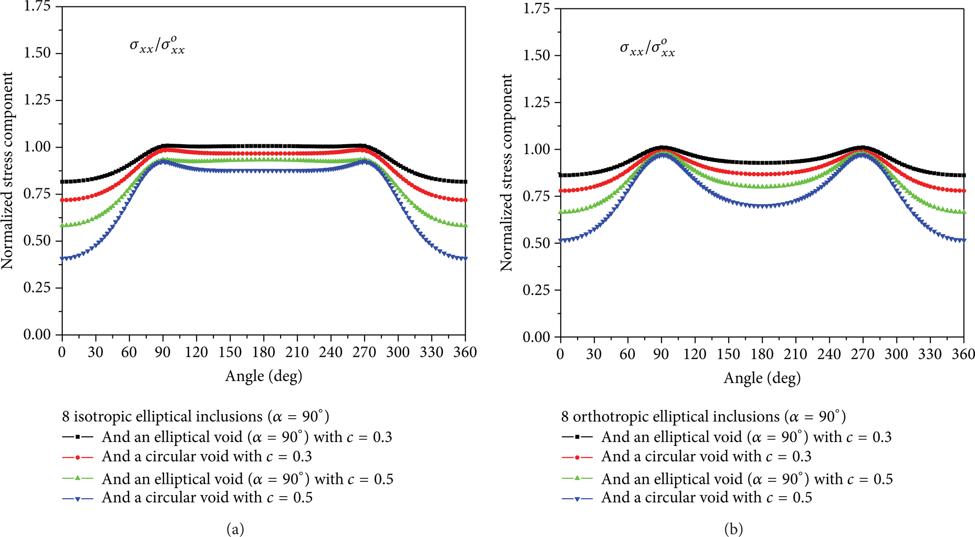
Normalized tensile stress component (σ xx /σ xx °) at the interface between the central (a) isotropic and (b) orthotropic elliptical inclusion and the isotropic matrix under uniform remote tensile loading for the square packing of 8 (a) isotropic and (b) orthotropic elliptical inclusions and one circular/elliptical void at an inclined angle α = 90°.
Figures 8, 9, 10, and 11 show that the stress at the interface between the matrix and the central inclusion appears to decrease as the orientation angle increases for all cases considered. Given these results, it is therefore necessary to model arbitrarily oriented isotropic or anisotropic fibers with arbitrary geometry and various void shapes in order to accurately predict the failure and damage mechanisms in real composites.
5. Concluding Remarks
Cross sections of certain composites have been shown to contain fibers of near elliptical shape with varying orientation angles. If voids are caused by manufacturing and/or service induced defects, they may have a significant effect on the local stresses in a composite. For this reason, the stress field at the interface between the matrix and the central isotropic/orthotropic inclusion was investigated through the square packing of eight isotropic/orthotropic elliptical inclusions of arbitrary orientation and one circular/elliptical void with an aspect ratio of 0.5 under uniform remote tensile loading, taking into account different values for the orientation angles and concentration of the inclusions. It was observed that (1) the stress at the interface between the matrix and the central inclusion decreased as the orientation angle increased for all cases considered, (2) the interfacial stress of the central elliptical inclusion with an elliptical void was greater than that of the central elliptical inclusion with a circular void, and (3) the interfacial stress of the central isotropic elliptical inclusion was greater than that of the central orthotropic elliptical inclusion, since c11 in the isotropic inclusion was greater than that in the orthotropic inclusion. In addition, it was also discovered that as the fiber volume fraction increased, the interaction effect became weaker except for the square packing of eight isotropic elliptical inclusions and one circular/elliptical void at an inclined angle α = 0°.
Through the analysis of plane elastostatic problems in an unbounded isotropic matrix with multiple isotropic or anisotropic elliptical inclusions of arbitrary orientation and a circular/elliptical void under uniform remote tensile loading, it was further noted that in order to accurately predict the failure and damage mechanisms in real composites, it is necessary to investigate multiple arbitrarily oriented isotropic or anisotropic fibers with arbitrary geometry and various void shapes under arbitrary loading conditions [20, 21].
Footnotes
Acknowledgments
This research was supported by Basic Science Research Program through the National Research Foundation of Korea (NRF) funded by the Ministry of Education, Science and Technology (Grant no. 2012-0007636). The authors would also like to acknowledge the support from Korea Institute of Science and Technology Information (KISTI) supercomputing center through the strategic support program for the supercomputing application research (no. KSC-2012-C1-06) and appreciate their assistance in parallelizing and optimizing the VIEM code cited in this paper.