
Abstract
Simulation technologies provide necessary validation tools for the conceptual design of complex products involving multiple disciplines. A variety of simulation models are developed in specific organizations or enterprises to verify the design plan, while they are hard to be shared and to be reused. Based on the analysis of several typical solutions to share and reuse different kinds of resources, a simulation model design method is proposed to provide a simple implementation of simulation model reuse for cloud-based simulation environment. This paper firstly creates the simulation models' metamodel and ontology for their universal description. Secondly, four rules are proposed to design/reprogram a simulation model into service-oriented form for its interoperability, and the ontology of service-oriented simulation model is established. Thirdly, the way to call one simulation model and the way to compose several simulation models into a simulation process are elaborated. Finally, a simple case of using this method to design an aircraft dynamic model is elaborated, and a prototype simulation system is constructed, and then a simple simulation process is composed to verify the practicability of the method. The result shows that the new design/reprogram method has big advantages on the compatibility, expansibility, and reusability despite the decreasing efficiency.
1. Introduction
The design process of modern product is a process in which uncertainties are gradually reduced, and it involves a series of iterative stages mainly including conceptual design, detailed design, simulation analysis, manufacturing, and sale. In this process, as much information as possible is gradually collected, and the engineers need to make design plan firstly and then improve them based on the information. The least amount of information is at the conceptual design stage which usually contains only some vague requirements, so engineers have to add a lot of background information by using variety of tools, their experiences, and their knowledge to get a solution to meet these requirements. As the starting point of the design process, the conceptual design puts significant influences on the subsequent stages, and its design result directly determines the consumptions of time, money, and manpower in the whole design process. For engineers, it is an eternal pursuit to reduce the number of iterations in the design process, and one of the efficient ways is to improve the quality of conceptual design.
Researches are carried out by scholars from different angles to improve the quality of the conceptual design, they typically include the quality function deployment (QFD), house of quality (HoQ), theory of inventive problem solving (TRIZ) and fuzzy set theory [1–7]. When some key parameters of a design plan in the conceptual design stage are determined, computer simulation technology is an efficient way to verify its validity. Different simulations in fact bring additional and hypothetical information which embedded in the simulation models to verify the design plan under some established conditions. Because most of the simulation models are mathematical, and they could be ran on some computer at small consumption of time and money, engineers develop variety of simulation models which plays an important role in specific organizations or enterprises.
With increasing degree of product complexity, more and more disciplines are involved and large-scale interdisciplinary collaboration design becomes mainstream. More and more simulation models are needed to perform different kinds of simulations, and some problems emerge, for example: (1) sometime, it is not possible to find a suitable simulation model to do a simulation task, because an enterprise cannot have all the simulation models which are available only within some specific organizations or enterprises; (2) sometimes, it is hard to find a suitable simulation model to do a simulation task according to some requirements, because these models are managed out of order; (3) sometimes, it is hard to reuse existed simulation models, because they are programmed to be ran under specific environments; (4) sometimes, it is hard to put some simulation models together to perform a simulation process, because they are interdisciplinary and heterogeneous, and they are programmed by different people in different programming languages at different times. These problems mainly are caused by (1) limited application scope and low sharing degree of simulation models; (2) unordered management of simulation models; (3) high dependency to specific environment (operation system or software) of simulation models; (4) interaction difficulties of interdisciplinary heterogeneous simulation models.
Faced with similar problems, different groups made some specific attempts to achieve the goal of sharing and reusing different kinds of resources. Some typical solutions are listed as follows.
Simulation model portability (SMP) [8] is an attempt to enable reuse and portability of simulation models between simulator applications. It is a standard for simulation models developed by European Space Agency (ESA) together with various stakeholders in the European space industry. SMP is based on the ideas of component-based design and model-driven architecture (MDA) as promoted by the Object Management Group (OMG) and is based on the open standards of UML and XML. The development of a simulation model and the run-time environment according to the SMP standard is very complicated, but good interaction between different models can be guaranteed, and a large-scale simulation process can be composed by using these simulation models quickly.
MyExperiment [9] is designed as a social web site for discovering, sharing, and curating scientific workflows and experiment plans. The MyExperiment builds a collaboratively supported workflow repository over the internet, and all the my Experiment services are accessible through simple representational state transfer (REST) programming interfaces. A developer can develop a workflow in specific development environment and share it on my Experiment. A user can find and download a workflow from my Experiment and then run it in Taverna [10] on his own computer.
NanoHUB [11] is designed to be a resource to the entire nanotechnology discovery and learning community. The NanoHUB collects simulation tools and flash-based animations/presentations from different groups or individuals and shares them over the internet. A developer can develop a simulation tool by using the Rappture Toolkit [12] and share it on the nanoHUB easily. A user can find a simulation tool and run it directly on the web page, and all the software needed for a user is just the Java for web browser.
RunMyCode [13] is a cloud-based platform allowing people to run computer codes associated with a scientific publication (articles and working papers) using their own data and parameter values. The RunMyCode is possible to create a companion website from a code written in R, Matlab, C++, Fortran, and Rats. A user can find and run a code directly on the web page, and the result is shown in the form of *.pdf.
While the above solutions have different emphases, their core concepts (sharing and reusing) are the same. A simple comparison of these solutions is shown as follows (Table 1).
Comparison of typical sharing and reusing solutions.

Regardless of the involved or not involved specific cloud computing technologies, the MyExperiment, nanoHUB, and RunMyCode are all in line with the core concept of cloud computing which offers different kinds of resources as services for users over the internet [14, 15]. The cloud computing brings bright prospects for the resources sharing and reusing, and more and more scholars propose cloud-based simulation environment. The schema and paradigm of cloud-based environment are stated [16, 17]. The calling method of simulation models by using intelligent agent is proposed [18], and the integration method to plant existing simulation software into the cloud is studied [19]. These jobs are more concerned about the theory and some specific methods of this new concept. All these attempts are trying to build an ideal simulation environment in which all the interdisciplinary heterogeneous simulation models: (1) can be freely called within a large scope (over the internet); (2) can be managed orderly; (3) can be decoupled from specific environment (operation system or software); (4) can interact with each other easily.
The above solutions can be said to be some specific implementations for these goals; however, they only partially meet these goals. The SMP mainly achieves the fourth goal above, and it is powerless to the first three goals. Besides, the high development difficulty and limited application scope of SMP determine that it is not an efficient way to achieve the sharing and reusing simulation models. The MyExperiment achieves the first two goals, but it is highly dependent on some specific software. The nanoHUB and RunMyCode achieve the first three goals. While these resources (workflows/tools/codes) are being shared well over the internet, the MyExperiment, nanoHUB, and RunMyCode are not able to achieve the fourth goal, because these resources are designed without the consideration of interaction capability. It is obviouse that simulation processes cannot be composed freely by using simulation models which has no interaction capability with other simulation models.
In order to build a cloud-based simulation environment which can achieve these four goals, the most basic thing is to make the simulation models well designed for the sharing, reusing, and interaction, and there is almost no relevant work that pays attention on the design method of a simulation model. Aiming to provide a simple design method of simulation model for cloud-based simulation environment, this paper proposed a design/reprogram method. Section 2 creates the simulation models' metamodel and ontology for their universal description. In Section 3, four rules are proposed to design/reprogram a simulation model into service-oriented form for its interoperability, and the ontology of service-oriented simulation model is established. In Section 4, the way to call one simulation model and the way to compose several simulation models together into a simulation process are elaborated. In Section 5, a simple case of using this method to design an aircraft dynamic model is elaborated, and a prototype simulation system is constructed, then a simple simulation process is composed to verify the practicability of the method.
2. The Metamodel and Ontology of Simulation Model
In order to eliminate the ambiguity in this paper, the simulation model is defined as computer program or code programmed according to some formula, algorithm, or rules, it has fixed inputs, functions, parameters, and outputs, and it has many kinds of forms typically including *.exe, *.c,*.dll, *.lib, and *.m.
The characteristics of different simulation models are not the same. Some can run automated without human, and some take knowledge and experience of the people involved. Some do not have the ability to interact with the others, and some can directly read/write data from/to some specially formatted files. Some can be directly invoked, and some must be precompiled. Some depend on specific software environment, and some do not. Based on some common features, a metamodel of simulation model is represented as a seven-tuple:
P i = {pi1, pi2, …, p in } is a set of configurable parameters of one model. The parameters are defined in this paper as some data items that directly participate in the operation of the model, and they can be flexibly configured before a simulation, and they do not change during the simulation process. Each p ij (1 ≤ j ≤ n) can be described by its significant properties including name, index, data type, default value, range of value, and dimension.
ID i = {idi1, idi2, …, id im } is a set of input data items of one model. The input data items are defined in this paper as some date items that directly participate in the operation of the model, and the values of these data items are changing with the simulation time's changing, and the values of these input data items can be obtained from different places including user's input, other models' output, and some global variables (e.g., global clock tick of time-driven simulation environment, global message of event-driven simulation environment). An input data items set is an ordered data block, and each id ij (1 ≤ j ≤ m) is marked by its name, index, data type, memory size and offset address, and so forth.
OD i = {odi1, odi2, …, od io } is a set of output data items of one model. The out data items are defined in this paper as some data items for the recording of the operation results, and the values of these data items are generated by the calculation of the model according to its parameters and input data items. An output data items set is an ordered data block, and each od ij (1 ≤ j ≤ o) is marked by its name, index, data type, memory size and offset address, and so forth.
CC i = {cci1, cci2, …, cc ip } is a set of control commands of one model. The control commands are defined in this paper as names of some functions that drive the status changing of this model. The typical control commands include initialization, start, step, pause, and end. Generally, the control commands are some functional gateway exposed by the model for the necessary controlling from the outside.
SC i = {sci1, sci2, …, sc iq } is a set of static characteristics of one model. The static characteristics are defined in this paper as some properties that do not change with the changes of simulation process or simulation environment. The static characteristic typically includes model name, model version, model function, model accuracy, single-step-generated data size, and step range.
DC i = {dci1, dci2, …, dc ir } is a set of dynamic characteristics of one model. The dynamic characteristics are defined in this paper as some properties that change with the changes of simulation process or simulation environmental. The dynamic characteristics typically includes calling method, calling path, and computation time in single-step.
C i = {ci1, ci2, …, c is } is a set of applications (including operating system) and components that depend on one model.
The metamodel reflects the most essential features of simulation models without the consideration of specific implementation method. According to this metamodel, the ontology of simulation model can be established as shown in Figure 1.

The ontology of simulation model.
3. The Service-Oriented Simulation Model
Once the metamodel of simulation model is created, it can be used to create a management system for the simulation models, and users can search appropriate simulation models according to their characteristics for different simulation tasks. If simulation models are chosen for simulations separately without the need of interaction between different models, there is no need to do any change to different kinds of simulation models, but there is need to construct different calling engines for them. But in most cases, different kinds of simulation models are needed to be composed together into a simulation process to do a specific simulation task, and some problems emerge including (1) some models have no ability to interact with others, and (2) while some models have the ability to interact with others, the interaction methods are not the same. So, some design/reprogram works and some design/reprogram rules are needed for the free interactions among different simulation models. Service-oriented architecture (SOA) can be a powerful technology for the design/reprogram work of simulation models.
SOA is proposed as a kind of architecture for developing distributed system by Gartner Group in 1996. It is a software design methodology based on structured collections of discrete software modules, known as services that collectively provide the complete functionality of a large or complex software application [20]. SOA separates functions into distinct units or services, which developers make accessible over a network in order to allow users to combine and reuse them in the production of applications [21]. SOA can achieve seamless combination and interaction between heterogeneous applications/programs/modules through the well-defined interfaces, contracts and by passing data in a well-defined, shared format [22]. It is a proper way to design/reprogram a simulation model into a SOA-based service.
As a software design methodology, there are many SOA implementation methods. Take the Windows Communication Foundation (WCF), for example, for the above meta-model, where the general strategy is to define the P i , ID i , and OD i as data contract, to define the CC i as operation contract, to define the message contract, fault contract, and service contract, and then publish these contracts by metadata through a uniform resource identifier (URI). When a user wants to compose several simulation models together into a simulation process, he needs to find these models and get their contacts through their URIs, and then write a program to call these models without rewriting them. Despite the fact that programming workload will be more less than rewriting all the models, there are still some annoying programming works such as defining different classes and data structures for the parameters described in the operation/data contract of different models. The problem is caused by the need of getting the data structure in the model and the need of passing parameters to the model's operations. To eliminate these programming works, a set of rules are proposed to construct a simulation model.
Each model has one named modelOnto.xml file, in which all the information shown in Figure 1 is recorded. According to this file, details about a simulation model can be easily parsed and stored into a models database.
Each model has one named dataInterRela.xml file and its structure as shown in Algorithm 1.
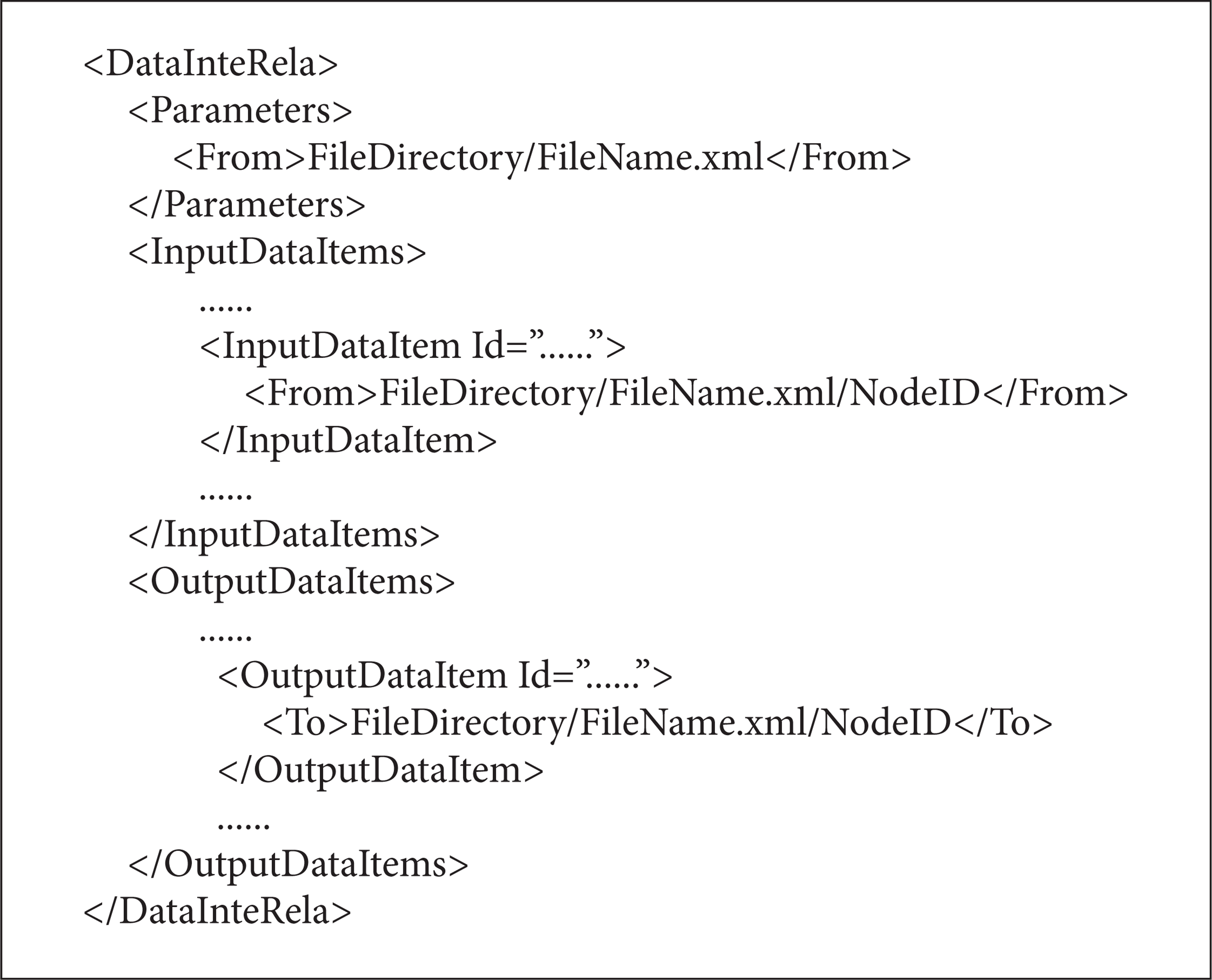
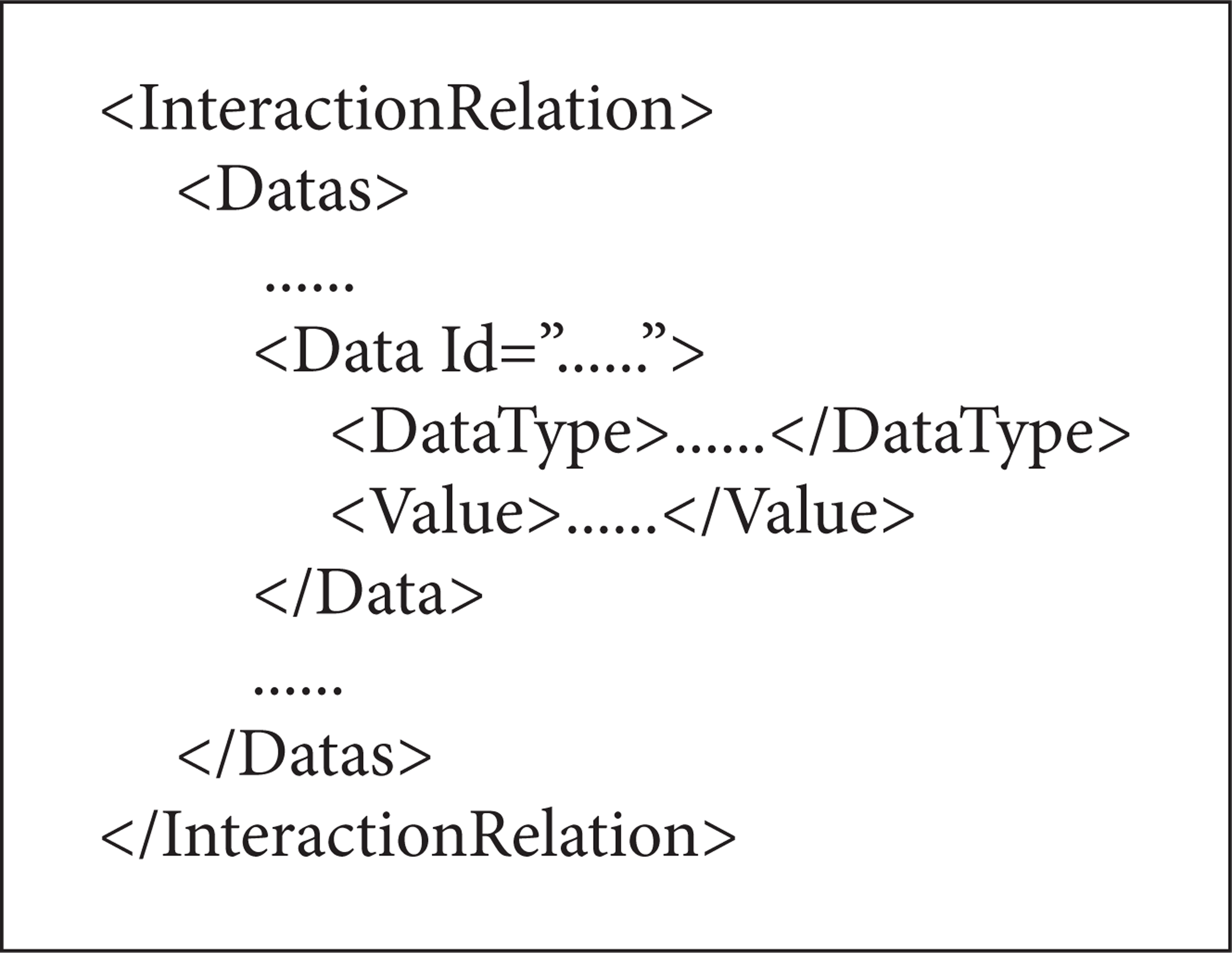
This file records a set of *.xml file paths marked by <From></From> or <To></To>. All the parameters corresponds to one *.xml file, while each input/output data item corresponds to one *.xml file. These *.xml files are used as the intermediate files for the data interaction between different models, and these *.xml files' structures are very simple (see Algorithm 2).
It is noteworthy that multiple input/output data items could point to one same file.
Each model exposes an “init” function to read the dataInterRela.xml to get all the paths of data interaction files.
Each model exposes a “step” function to drive it to get parameters and input data from the corresponding *.xml files pointed by the file paths mentioned in rule 3, does calculation, and puts output data into the corresponding *.xml files.
These rules can be described by Figure 2.

Four rules to design/reprogram a simulation model.
When a simulation model is designed or reprogrammed in accordance with these rules, only service contract and operation contract are needed to be defined, and there is no need to pass values for the operation contract, so there is no need to define the data contract. All the work to call a simulation is to operate some fixed format temporary *.xml files, and this work can be easily done by some XML parser and XML generator.
The ontology of service-oriented simulation model can be established as shown in Figure 3.

The ontology of service-oriented simulation model.
There are three main parts to describe a service-oriented simulation model: the “Model Ontology” is employed to describe the most essential information mentioned in Section 2 of a simulation model without the service-oriented implementation, and the model ontology is recorded and presented by the “modelOnto.xml.” The “Interactions” is employed to describe the data interaction relationships which are defined as the mapped relationships among multiple *.xml files and the parameters/input/output data items, and these mapped relationships are recorded and presented by the “dataInterRela.xml.” The “Service Profile” is employed to describe the service information of service-oriented simulation model, and the service information is usually recorded and presented by a “ServiceConfig.cfg” based on specific SOA implementation method.
Based on the concept above, the overall architecture of a service-oriented simulation model is shown in Figure 4.

The overall architecture of service-oriented simulation model.
A service-oriented simulation model should include four parts: (1) a hosting process (*.exe or IIS) which hosts the specific implementation of a simulation model; (2) a “ServiceConfig.cfg” file which controls the EndPoint exposed by this service-oriented simulation model; (3) a “modelOnto.xml” file which describes the information of the simulation model; and (4) a “dataInterRela.xml” which records the mappings between all parameters/input/output data items and some temporary generated *.xml files.
In a classic service-oriented architecture, the EndPoint is used to expose the details of a service. The EndPoint includes three parts: (1) the Address identifies a URL where the service can be found, (2) the Binding identifies what communication ways should be used to access this service, and (3) the Contract identifies what operations can this service do through the interfaces defined in this service. There are two interfaces in the specific implementation of a simulation model: (1) the IModel exposes the main operations expressed as OperationContract; (2) the ImodelCallBack is used to expose the callback states of the two operations include init() and step(). The main logic of init() and step() is shown in Algorithm 3.

When some service-oriented simulation models are built, a service consumer client can be constructed to manipulate these models. A ModelController can be built to read and edit the modelOnto.xml file to manipulate the information of a model. A ServiceController can be built to read, edit, and delete the ServiceConfig.cfg to manipulate the information of this service, and it can control the service to Start or Stop. A ModelController can be built to drive a model to init() or step(). Based on these basic function modules, more function modules can be built in the service consumer client, for example, the Service Manager to control all the services, the ModelManagere to control all the models information. This paper will not go into detail contents of the Client because it is not the focus.
4. The Calling of Simulation Models
When a simulation model is programmed into its service-oriented form according to the rules above, it needs to be registered to a simulation models registry as the UDDI (Universal Description, Discovery and Integration) registry. In this Simulation Models Registry, in addition to the description, discovery and integration of simulation models, there is a very important task to establish coarse-grained classification rules in a specific field to support the model searching and model matching for users. Users can search a simulation model or some simulation models according to these coarse-grained rules and then get further information about it/them by reading the database or by parsing the corresponding modelOnto.xml files.
If only one simulation model is selected and to be called, a dynamic user input interface which contains the P i and ID i , a temporary input.xml and a temporary output.xml in a structure described in Section 3 are generated, and the paths of the input.xml and output.xml are wrote into the model's dataInterRela.xml; the user input interface will collect the user's inputs and write them into the input.xml and then drive the model to get these data and do calculation; the results will be written into the output.xml. The data interact process is as shown in Figure 5.

The data interaction process of the calling of one simulation model.
When several simulation models are selected to compose a simulation process, the data interaction relationships among these models need to be configured manually, and each data interaction relationship can be expressed as a mapping from one model's one output data item to another model's one input data item. Finally, a simulation process SP
i
(i ∈ N) can be represented as a five-tuple:
SPC i = {spci1, spci2, …, spc in } is a set of characteristics of the simulation process. They typically include the process name, simulation purpose, step length, start time, and end time.
SPM
i
= {Mi1, Mi2, …, M
in
} is a set of models employed in the simulation process. Each
SPMR i = {MRi1, MRi2, …, MR im } is a set of data interaction relationships among these modules. The SPMRi is a set of mappings between the collection of all models' outputs O i = {ODi1, ODi2, …, OD in } and the collection of all models' inputs I i = {IDi1, IDi2, …, ID in }, and SPMR i : O i → I i . Each MR ij (i ∈ N, 1 ≤ j ≤ m) is a rule point from a model's one output to another's one input, MR ij : od irk → id isl (od irk ∈ OD ir , OD ir ⊂ O i , 1 ≤ r ≤ n, k ∈ N, id sl ∈ ID s , ID s ⊂ I, 1 ≤ s ≤ n, l ∈ N, i ∈ N, r ≠ s).
SPS i = {MSi1, MSi2, …, MS io } is a set of modules marked as the starting point of a simulation process, and each MS ij ∈ SP Mi (1 ≤ j ≤ n).
SPE i = {MEi1, MEi1, …, ME ip } is a set of modules marked as the ending point of a simulation process, and each ME ij ∈ SPM i (1 ≤ j ≤ n).
The ontology of simulation process can be established as shown in Figure 6.

The ontology of simulation process.
The configuration of a simulation process mainly includes model selection, data interaction relationships configuration, and model parameters/input configuration. Model selection is responsible for selecting appropriate models to meet the simulation demands. When several models are selected, the user input interface of each model's P i and ID i is generated for the configuration by users, and then users need to input appropriate values for each model's parameters, create data interaction relationships between different models' inputs and outputs, and manually input necessary data for some models' input data items which cannot get data from other models' output. All the configuration information is formatted into a process description file in the form of .xml. The structure of this.xml is described in Algorithm 4.

After this, some temporary.xml files are generated for the data interaction according to the data interaction relationships marked by <Interaction Relations></Interaction Relations> in the simulation process description file. The simulation process can be driven by a workflow engine which can parse the simulation process description file to get the execution order of each model. The data interaction process of a simulation process SP i is as shown in Figure 7.

The data interaction process of the calling of several simulation models.
5. Case Study
Based on the concepts above, a 6 degree of freedom (DOF) aircraft dynamic model built in Geodetic Coordinates is programmed into two different ways to get flight paths. A flight path is divided into 5 stages including taxi, ascending, level flight, harmonize turn, and landing in this model. The first way is written in Matlab by using fourth-order Runge-Kutta method to calculate the position of the aircraft, and the second one is written in C# by using Newton's method to calculate the position of the aircraft.
Both of the two ways contain the same parameters and input data items. The parameters include the step st; the initial rate v0, the initial azimuth ψ0 (North by East), and the initial height h0 in the taxi stage; the ascending start time tas in the ascending stage; the level flight start time tlf in the level flight stage; the harmonize turn start time
The Matlab-way generates an aircraft-matlab.m file which cannot be directly a service, so some more programming works are carried out to make it a service by using WCF and Matlab Engines. The main logic of “init()” is listed as follows.
Start the Matlab Engine through the calling of corresponding *.dll and *.lib provided by Matlab and load the aircraft-matlab.m file;
Read the aircraft-matlab-dataInterRela.xml to get the file paths paraFileList<> of parameters configuration files, the file paths inputFileList<> of input data items files, and the file paths outputFilelist<> of output data items files.
Parse all the parameters in paraFileList<> and send them to the aircraft-matlab.m through the Matlab Engine.
The main logic of “Step()” is listed as follows.
Parse the input data items from the corresponding *.xml files according to the inputFileList<> and send them to the aircraft-matlab.m through the Matlab Engine.
Drive the Matlab Engine to run the aircraft-matlab.m.
Get the results and write them into corresponding *.xml files according to the outputFilelist<>.
Unlike the Matlab-way, the C#-way can be directly programmed into a service by using WCF. The main logic of “Init()” and “step()” is similar to the functions in Matlab-way except the Matlab Engine part.
Because the level flight distance of a true flight path is too long to be shown in one scene, a simplified flight path between two different airports in a same city is planned. All the parameters are configured as st = 1, v0 = 0, ψ0 = 0, h0 = 0, tas = 40,


Two flight paths' projections in North.
The two flight paths have very small differences so that the curves almost coincide with each other. But the two ways' execution time of a single step has huge differences, as shown in Figure 10.

The comparison of two ways' execution time of a single step.
Each time the “Step()” is executed, the execution time is recorded, so there are 300 sampling points. These time differences are due to the program logics and algorithms. The fourth-order Runge-Kutta method spend more time than Newton's method, and the calling of Matlab Engine spend extra time.
Then some more simulation models are reprogrammed in WCF, and a prototype simulation system is constructed. A simple global navigation satellite system (GNSS) simulation process shown in Figure 11 is composed by using the 6 DOF aircraft model and some other models.

A simple simulation process.
This simple simulation process has five simulation models, and its main function is calculating the true distances between the satellites and a moving vehicle in a period of time. Each model's parameters, input data items, and output data items are shown in Figure 12. The [X s Y s Z s ] stands for the earth centered earth fixed (ECEF) coordinate array of satellites, and the X u Y u Z u stands for the ECEF coordinate of a vehicle, and the [TDs – u] stands for the true distance array of these satellites to the vehicle.

The structure of these five models.
Figure 13 shows the active service-oriented simulation models in the Simulation Models Registry. Figure 14 shows the main interface of simulation model selection, simulation process design, and data interaction relationship configuration.

The active service-oriented simulation models.

The main interface of simulation model selection, simulation process design, and data interaction relationship.
The simulation models used in this process are deployed on a local host to simplify the verification process, but they can be easily deployed on other hosts. The models can be selected from the “ModelList” panel which shows the active service-oriented simulation models. When clicked, a model's parameters/input-data-item/output-data-item are listed in the “Para/Input/Output” panel on the right side, and the parameters can be configured here. A simulation process can be composed by creating interaction relationships between different models just as shown in the subwindow “DataInteractionConfig.” The simulation process is driven by a simple event-driven engine, and each service's callback function triggers the engine.
Although this prototype system is performed on a local host, all the models are programmed in WCF according to SOA standards and are formed into some *.exe files. So when be configured to a Public IP, all the models will be shared over the internet. In addition, the client as a validator is not necessary, because all the functions could be implemented on web pages. And we can know that users can run a *.m model without the Matlab on his computer from the running of the Matlab-way, that is to say that the decoupling of the users' clients from some specific software is implemented. Finally, users can compose some models to perform a simulation process.
6. Conclusion
Despite that the validation of this structure is relatively simple, conclusions can be drawn from the limited works: (1) service-oriented simulation models can be an available way of encapsulating specific simulation algorithms, programs, methods, and knowledge; (2) a well-designed/well-reprogrammed simulation model only interacts with some fixed format.xml files, and it reduces the coupling between the model and specific applications, and it is easy to reuse and easy to integrate; (3) different models interact by reading and writing some fixed format.xml files, and it reduces the interaction difficulties of heterogeneous modules; (4) a simulation model resource pool can be easily constructed for cloud-based or distributed environment by collecting these well-reprogrammed simulation models.
The design method proposed in this paper has some disadvantages: (1) this method is not suitable for time-driven simulation mode, because the increased file reading and writing operations will reduce the execution efficiency, and any failed execution of one model could crash the whole simulation process; (2) the parameters/input-data-item/output-data-item need to be format fixed; (3) the work to reprogram an existing simulation is a little hard although simple in form of this method; (4) there is no tools to design a model, and all the work need to be done manually by using a SOA implementation method such as the WCF.
Future works includes (1) improving this design method to fit the situation that the input/output data items' format is not fixed; (2) improving the process interpreter to support more complicated simulation process which contains the looping and branching structure; (3) developing web-based client; (4) doing more tests on distributed environment.
Footnotes
Acknowledgments
This work was supported by the National High-Tech, R and D Program, China (nos. 2011AA120505 and 2011AA040503), and the National Natural Science Foundation, China (no. 61173077).