
Abstract
This paper deals with the fault diagnosis methodology for the V/x-type traction transformer in railway passenger-dedicated lines. A kind of the protection methodology to combine empirical mode decomposition (EMD), energy weight, and information entropy is proposed. This method can sensitively reflect the dynamic information changes of traction transformer differential current, so it can not only effectively identify internal short-circuit fault current from magnetizing inrush but also better identify fault current accompanied with magnetizing inrush. In this method, the differential current is decomposed by EMD and the energy weight of each intrinsic mode function (IMF) is calculated, and the feature vector of the fault pattern recognition is obtained by constructing IMF energy entropy. The field-measured data illustrate that the new method not only has the advantages of high sensitivity, faster identification speed, and clear concept but also is available for the diagnosis of the complicated dynamic system.
1. Introduction
V/x-type traction transformer is one of the key equipments in the power distributing system of high speed train way. Fault protection is the important technology to guarantee the reliable operation of the V/x-type traction transformer in traction power supply system (TPSS). The application experiences show that the internal short-circuit fault will bring about serious consequences to system operation; thus the differential-fault-protection system of traction transformer must have the ability to correctly identify this fault and to carry out the real-time protection. However, unfortunately, for the traction transformer with large power, the great difficulty is that magnetizing inrush and fault current are of the approaching signal characteristics in signal shape. As the magnetizing inrush is the impulse current produced by the nonlinear magnetic flux-electric current characteristics while transformer switching without load, whose amplitude is close to the amplitude of internal short-circuit fault current, it is very difficult to distinguish them only according to the current amplitude value. This undoubtedly brings difficulties to the design of differential-fault-protection system, if the magnetizing inrush and fault current could not be quickly and accurately distinguished by protection system, multiple sequential closing and charging for the traction transformer will be conducted, which will seriously shorten the service life of transformer. More thorny and serious problem is that internal short-circuit fault current which accompanies magnetizing inrush while switching without load; this condition should be regarded as fault behavior, but it is probably not identified. Therefore, to distinguish between magnetizing inrush and fault current quickly and correctly has become an urgent problem to be solved in differential-fault-protection system of traction transformer.
Currently, the second harmonic protection principle has been widely used in engineering applications as differential-fault-protection method of traction transformer. However, due to the resonance influence from compensation capacitor of high-voltage transmission line and the decline of magnetic saturation point of the traction transformer, it causes the difference weakening of the second harmonic characteristics between magnetizing inrush and fault current and finally results in the increment of the malfunction rate in differential-fault-protection. Therefore, in order to improve the differential-fault-protection performance of traction transformer, we must search the new features and quickly and correctly distinguish magnetizing inrush from fault current.
According to the recognition principle of the fault feature, the differential-fault-protection methods of power transformer can be roughly divided into two types: model-based and signal-processing-based methods according to waveform characteristics. Model-based identification methods have flux linkages increment method [1], combined method of magnetizing inductance and loop equilibrium equation [2], equivalent circuit parameters method [3], magnetic flux symmetry property method [4], dynamic impedance characteristics [5], and so forth. Advantages of this type of methods is that it is able to distinguish magnetizing inrush from internal short-circuit fault current on the presupposition that the related electric parameters can accurately be acquired, but some main electrical parameters cannot be accurately measured in the practical applications. Diagnosis methods based on waveform characteristics signal processing are improvement or evolution of the second harmonic principle and the intermittent angle method, such as waveform distribution characteristics method [6], normalized grille curve method [7], wavelet transform method [8], neural network method [9], intelligent hybrid method [10], sine wave distortion characteristics method [11], voltage and current waveforms combined method [12], fundamental current amplitude method [13], mathematical morphology method [14], and so forth. Such methods have the advantage of clear principle, but they are subject to the effect of the nonperiodic component factors.
Traction transformer is different from power transformer in negative-sequence component and harmonics content of differential current. There is only little relevant literature about improved method of traction transformer differential-fault-protection, most of which are model-based method, such as unsaturated zone equivalent instantaneous inductance identification method [15], winding resistance and leakage inductance parameter method [16], and transformer structural modeling method [17], but these improved methods are also difficult to be applied in engineering because of the electrical measurement limits. In contrast, the waveform-based identification method of power transformer has more reference value because of its convenience in electrical measuring, and this method will be a better idea to improve differential-fault-protection of traction transformer by further upgrading algorithm.
Huang proposed a signal processing method based on empirical mode decomposition (EMD), whose basis functions are generated based on the signal itself characteristic scale, which have a clear physical meaning for dealing with nonlinear and nonstationary signals and have been applied in the field of mechanical vibration [18], radar location [19], frequency analysis of power system [20], and some other fields. Magnetizing inrush and fault current belong to nonlinear and nonstationary signals, and they have essentially different in the frequency components features, thus the protection method combining EMD, energy weight, and information entropy is suitable for the working state diagnosis of V/x-type traction transformer. This paper focuses on this new methodology; the differential current signals are first decomposed into a number of IMF components under different time scales using EMD algorithm and the energy weight of each intrinsic mode function (IMF) and differential current signal is calculated in a power cycle. Then the IMF energy entropy is constructed based on energy weight which is sensitive to variation of differential current information, and this entropy value is defined as the feature vector of distinguishing between magnetizing inrush and internal short-circuit fault current.
2. Feature Extraction and Identification Algorithm
2.1. Decomposition Principle of EMD
The empirical mode decomposition (EMD) algorithm is a new signal analysis method, which can simultaneously and gradually decompose the signal according to different scales or frequency fluctuations or trends to produce a series of the narrow-band stationary data sequence with different characteristic scales; it is called intrinsic mode function (IMF). Thus, the essence of EMD algorithm is extracting the inherent fluctuation mode based on feature time scale of the data and then decomposing the data. For complex multicomponent signals, its decomposition should meet two conditions: (1) the number of its extreme points and zero-crossing points should be equal or differ by 1 at most; (2) at any extreme point the mean value of upper and lower envelopes curves remains zero. For an actual signal x(t), the EMD algorithm is shown as follows.
Step 1. Determine all the extreme points of the signal x(t).
Step 2. Calculate the upper and the lower envelopes of x(t) using the cubic-spline function. In order to obtain easily the envelopes, the end effect needs to be curbed by adopting the mirror-extension extreme point method at both ends of the signal.
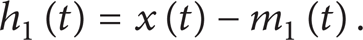
Step 3. Calculate the mean m(t) of the upper and the lower envelopes, and define
Step 4. Judge whether the h1(t) meets the IMF conditions. If the condition is not satisfied, let x(t) = h1(t) and return to Step 1; else set h1(t) as the first IMF component of the signal x(t). After executing k loops, get h1k(t) = h1 (k – 1)(t) – m1k(t) and the h1k(t) meets the IMF condition. Define c1(t) = h1k(t), c1(t) is called the first IMF component of signal x(t). Generally, this calculation process of IMF component is called the screening method and the class Cauchy convergence criterion is adopted to judge each screening result. The equation of class Cauchy convergence criterion is

In (2), the value of S D is generally set from 0.2 to 0.3.
Step 5. Extract the c1(t) from the x(t), and define
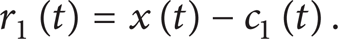
After designating r1(t) as the new input signal and returning to Step 1, get the second IMF component. If the nth loop is carried, the nth IMF component is obtained. That is,

When r
n
(t) is a monotonic function or
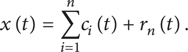
Therefore, the actual signal x(t) is decomposed into n IMF components and a residual r n (t), and r n (t) is a trend or constant signal.
2.2. Principle of Energy Weight
For description of the differential current signal, the energy accompanied by time scale distribution is one of the most important parameters. When magnetizing inrush and fault current of traction transformer occur, the differential current signal will change greatly, whose typical feature is that the signal energy variation depends on the distribution of time and frequency, and each frequency component contains lots of features message. Therefore, the essential feature message of magnetizing inrush and fault current can be got by analyzing the differential current signal in the different operating conditions. It can be learned from decomposition principle of EMD that the IMF components achieved by dividing different time scale of signal are a group of narrow-band stationary series of local instantaneous frequency ordered from the highest to the lowest. Therefore, for the differential current signal, the IMF energy in different frequencies can reflect the running state of traction transformer.
To construct the energy feature vector at different frequencies which can better represent the differential current signals, the concept of energy weights is presented in this paper. Its essence is to describe the arithmetic square root of ratio of each IMF component energy and differential current signal energy in the data-window using statistical methods. Assuming that the single-phase differential current signal has k components (including the residual) treated by EMD, which indicates it has k multiscale components, the energy weight λ c i (n) of a component c i in the nth power cycle is

where Ec i (n) and Ei(n) are, respectively, energy parameter of IMF component c i and differential current signal in the nth power cycle; N is the data length in a power cycle.
Equation (6) shows that the energy weight λ c i (n) reflects the correlation degree between IMF component c i and differential current signal in a power cycle (representing all feature information under a single time scale), while the energy weight of whole IMF components represents all of the messages contained in the signal in many feature scales during a power cycle. So, the corresponding relationship between differential current signal and IMF component is established by energy weight, which provides basic conditions for further quantifying current characteristics.
2.3. Construction of Feature Vector
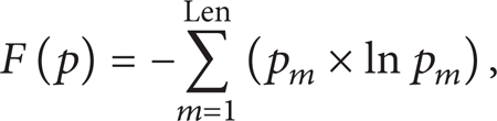
For the fault diagnosis, it is very important to select the parameters that can best reflect fault characteristics. Because the magnetizing inrush is the seriously distorted sine waveform while the fault current remains roughly sine waveform, the IMF component of two types of current will inevitably lead to differences in the number and energy weight. In order to better represent the essential characteristics of dynamic differential current in traction transformer, the concept of entropy in information theory is introduced to further describe the average information quantity of differential current. The entropy can provide useful information of the signal potential dynamic information, whose value is an accurate measure of average uncertainty and complexity of signal change [21]. The entropy F(p) is defined as
where
Obviously, the information entropy is a measure of the signal uncertainty degree, and the more uncertain and complex is the signal, the greater its entropy value is. After differential current signal of traction transformer is treated by EMD in a power cycle, IMF component at different time scale is utilized to ascertain the change information of differential current signal. Furthermore, if we define each time scale as an information source, the IMF component at single scale can be regarded as a message from the information source. Therefore, the IMF energy entropy is constructed by information entropy, EMD, and energy weight, which can sensitively reflect the weak and cramped change of differential current. Assuming that the current signal has k components (including the residual) treated by EMD in the nth power cycle, the total energy weight λall(n) of differential current signal is

The

Therefore, the IMF energy entropy vector J(n) of single-phase differential current signal in the nth power cycle can be constructed as follows:
It can be learned from (9) that the IMF energy vector J(n) reflects the energy distribution of differential current signals at different scales, and the value of vector J(n) is smaller for internal short-circuit fault current while the vector J(n) is greater for magnetizing inrush.
3. Differential Current Signal and Magnetizing Inrush of Traction Transformer
3.1. Differential Current Signal
In the TPSS of railway passenger-dedicated lines, the most typical traction transformers are V/x-type wiring transformer group which is connected with two single-phase three-winding transformers by V-type. Such traction transformer has the advantages of high capacity utilization and two windings configured respectively, and its differential-fault-protection wires are shown in Figure 1. In addition, to increasing the power supply distance of feeder, the output of traction transformer is connected to catenary, feeder, and parallel autotransformer (AT), while the locomotive gets power from catenary and rail (center tap of the secondary side in AT), so the input voltage of locomotive pantograph is half of the total voltage.

Differential-fault-protection wires of V/x-type traction transformers.
According to the ampere-turns balance principle, the transmission ratio of current transformer, and designation of current direction, the extraction principle of differential current signals (treated in the differential-fault-protection system using software method) is
where
3.2. Nonlinear Generating Mechanism of Magnetizing Inrush
Magnetizing inrush of transformer is generated by the core excitation saturation factor. As shown in Figure 2, the magnetization curve of traction transformer magnetic materials shows the typical nonlinear feature. That is, in a certain voltage, excitation current waveform not only depends on the core flux density B m but also depends on the core saturation degree. While B m < B s (which is saturated magnetic flux density), the transformer magnetic circuit is in unsaturated condition and the functional relationship between excitation current i and magnetic flux ϕ is linear. While B m > B s , the magnetic circuit begins to saturate, and the functional relationship between i and ϕ becomes nonlinear because the increasing speed of i is faster than the increasing speed of ϕ. Due to the core excitation saturation, the waveform of excitation current will be distorted into peak wave, and the deeper core saturation degree will cause the more serious distortion of excitation current waveform.

Waveform of magnetizing inrush.
Generally, there are mainly three operation conditions in traction transformer: transformer switching while without load; running with internal short-circuit fault; and switching without load but with internal short-circuit fault. This needs to be judged in differential-fault-protection system. The following is to test diagnosis effect and sensitivity of differential-fault-protection algorithm based on IMF energy entropy using field-measured differential current signal.
4. Diagnosis and Analysis of Actual Measured Current Signal
4.1. Magnetizing Inrush of Transformer Switching without Load
Figure 3 (a) shows that waveform of three single-phase ratio differential currents while traction transformer switches without load (a power cycle is 20 ms and the transmission ratio of current transformer is 1000: 1), and Figure 3 (b) depicts change of its IMF energy entropy vector.
Magnetizing inrush of transformer switching on without load.
Figure 3 (a) shows that the waveform of ratio differential current is distorted seriously while traction transformer switches without load, including unilateral and symmetrical magnetizing inrushes in waveform shape. As can be qualitatively analyzed in Figure 3 (b), the most significant characteristic is that the each single-phase IMF energy entropy vector J(n) is greater in a cycle, the minimum JC(n) is equal to 1.39, and the rest of vector value fluctuates from 1.40 to 2.02. And the other measured magnetizing inrush also meets this law.
4.2. Running with Internal Short-Circuit Fault
Figure 4 (a) shows the waveform of three-phase ratio differential current while the internal short-circuit fault of traction transformer occurs in running, and its IMF energy entropy vector is shown in Figure 4 (b).

Internal short-circuit fault occurring in operation.
It can be seen in Figure 4 (a) that a single-phase internal short-circuit fault of traction transformer happens in running, the three single-phase differential currents totally maintain the sine waveform shape, and the amplitude of fault phase is close to the amplitude of a nonfault phase (the reason is that current information is extracted by differential ways). As can be seen in Figure 4 (b), each single-phase vector J(n) is very small, and its value is almost close to 0.
4.3. Switching without Load but with Internal Short-Circuit Fault
Figure 5 (a) shows waveform of three-phase ratio differential current while traction transformer switches without load but with internal short-circuit fault, whose IMF energy entropy vector is depicted in Figure 5 (b). It can be seen in Figure 5 (a) that the DC component of differential current increases because of the coeffect of magnetizing inrush and internal short-circuit current at the same time, and the ratio differential current magnitude is larger for fault phase and a nonfault phase. In Figure 5 (b), the feature vector JA(n) of non-fault phase A is greater than 1.5 in 0.2 s, while JB(n) and JC(n) slowly reduce from a smaller value.

Internal short-circuit fault while switching without load.
4.4. Result Analysis of Actual Measured Data
In recent five years, many magnetizing inrush cases and some internal short-circuit fault cases were recorded in China's railway passenger-dedicated lines. After these current waveform data are treated by new feature extraction algorithm, the distributions of IMF energy entropy vector are shown in Tables 1, 2, and 3, respectively.
Feature distribution while transformer switching without load.

Feature distribution while running with internal short-circuit fault.
Feature distribution while switching without load but with fault.

Table 1 shows that the IMF energy vector J(n) of three-phase ratio differential current has the outstanding features in each cycle of the first 0.1 s: (1) all the feature entropy values are larger, including the smallest JB(2) = 1.26; (2) the feature vector shows good convergence.
It can be learned from Table 2 that the three-phases IMF energy entropy vector J(n) are all smaller in the first 0.1 s, such as the maximum vector JB(1) = 0.31.
As can be seen from Table 3, three-phase IMF energy entropy vector J(n) has the following features in each cycle of the first 0.1 s: (1) one phase IMF energy entropy value is larger, two-phase feature entropy values are smaller, and its value shows good convergence; (2) the gap between the lower limit of maximum entropy value and the upper limit of the minimum entropy value is very great.
According to comprehensive analysis of the above field-measured experimental data, some important conclusions are obtained.
Frequency component of internal short-circuit fault current is less and the energy of fault inrush is mainly focused on the few dominant components, while the frequency component of magnetizing inrush is rich and the energy of magnetizing inrush is scattered.
In three operating conditions, the IMF energy entropy value is stable in 0.1 s, thus the vector value of the first cycle (20 ms) is adopted to set threshold value and diagnose fault in order to improve the speed of identification.
In the first cycle, the three-phase feature vector of magnetizing inrush (when transformer switches without load) meets the conditions J(1) ≥ 1.32; three-phase feature vector of fault current (the internal short-circuit fault occurs in running) meets the conditions J(1) ≤ 0.31; and three-phase feature vector while transformer switches without load but with internal short-circuit fault meets the conditions of one phase J(1) ≥ 1.45 and the other two phases J(1) ≤ 0.76. Therefore, the spatial distance between fault status and nonfault status in the first cycle is 0.56 (1.32 – 0.76 = 0.56).
Assuming that the threshold value Jset(1) is set from 0.83 to 1.25 (choosing a reliable margin of 10%), fault current and magnetizing inrush can be correctly distinguished in the first cycle using the IMF energy entropy algorithm. In addition, it is proved by some field-measured current data that this conclusion also applies to the larger capacity traction transformer.
4.5. Comparison with the Tradition Protection Algorithm
At present, the second harmonic protection algorithm adopted single-phase brake is used as the differential-fault-protection method of traction transformer. Using the second harmonic method in the above operation conditions, the setting scope of three-phase ratio differential current from the first cycle to the fifth cycle is got and listed in Table 4.
Setting range of the tradition protection algorithm.
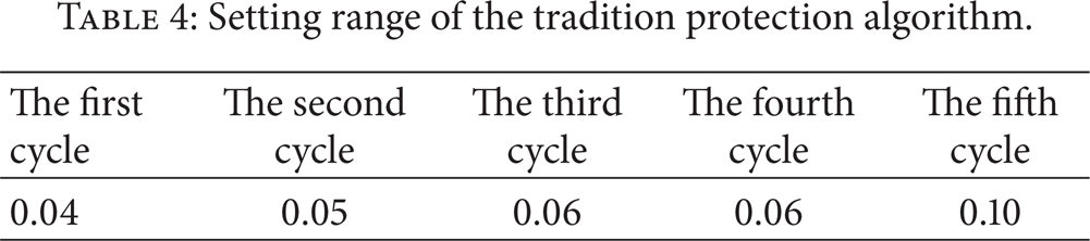
It can be seen from Table 4 that the setting range of the second harmonic protection algorithm in each cycle is very small, and the average setting range is 0.06 which is about one-tenth of the IMF energy entropy algorithm; thus it is the main reason of difficult setting for the traction transformer differential-fault-protection system. In addition, due to the fact that energy of the nonperiodic component will be diluted by the total energy, its influence on entropy values becomes smaller. Therefore, the new differential-fault-protection method based on IMF energy entropy in the accurate identification between magnetizing inrush and internal short-circuit current is not only better than the second harmonic method but also a good solution to the influence problems of non-periodic component.
5. Conclusion
The traditional differential-fault-protection performance of V/x-type traction transformer is seriously affected by the instability of the second harmonic component in magnetizing current, so a more reliable fault diagnosis methods need to be developed in engineering applications. According to the characteristics that there is a magnetizing inrush containing rich frequency components when traction transformer switches without load, while an internal short-circuit fault current is roughly a sine wave, the protection methodology combining empirical mode decomposition (EMD), energy weight, and information entropy is presented to identify magnetizing inrush and internal short-circuit fault current.
For the traction transformer, this method can sensitively reflect the dynamic information changes of differential current. If the IMF energy entropy values of three single phases are all large, it indicates that the traction transformer is switching without load (magnetizing inrush). If the IMF energy entropy values of three single phases are all small, it reflects that the traction transformer causes internal short-circuit fault in the operation. If the three single-phase feature entropy value shows such special phenomenon that a phase value is large while the two-phase value is small, it illustrates that the traction transformer is switching without load but with internal short-circuit fault.
It is crucial to achieve the new algorithm by selecting appropriate decomposition conditions. It has been found in experiment that, for the three-phase ratio differential current data of traction transformer, the EMD decomposition can be executed smoothly and quickly by using the mirror-extension extreme point method on border problem and the Cauchy convergence criterion on the termination conditions. Proved by some field-measured differential current data, the new algorithm based on IMF energy entropy has the advantages of high accuracy, faster identification speed, and clear concept; furthermore it is suitable to analyze complex and dynamic characteristics information of the traction transformer in railway passenger-dedicated lines.
Footnotes
Acknowledgment
This paper was supported by Scientific Research and Development Planning Projects “Study of Automation Systems Solutions and Technical Specifications in Traction Power Supply” in Ministry of Railways, China, under Grant 2007J022.