
Abstract
This study develops a strain measurement model for beam structures subjected to multiloading conditions by defining the strain-shape function and participation factors to overcome the limitations of strain measurements using fiber Bragg grating (FBG) strain sensors. Using the proposed model, the maximum strain in a beam is obtained by the sum of the strains caused by the different loadings acting separately. In this paper, the strain-shape functions for various loading and support conditions are provided, and a system of equations is defined to calculate the participation factors. Furthermore, the influence ratio is defined to identify the influence of each loading on the value of the total strain. The measurement model is applied to the monitoring of the maximum strain in a 4 m long steel beam subjected to two concentrated loads. For measurements during the test, seven FBG sensors and nine electric strain gauges (ESGs) were attached on the surface of the bottom flange. The experimental results indicate a good agreement between the estimated strains based on the model and the measured strains from ESGs. Furthermore, the dependency of the locations for the FBG sensors installed at the beam structure on the selection can be avoided using the measurement model.
1. Introduction
Structural members in buildings or infrastructures experience various loads, such as gravity-induced loads, earthquake, wind, or unexpected loads. To secure the safety of a structure, the maximum stresses in the members due to various loads must not exceed the allowable stress of a member [1, 2]. For this reason, strain-based structural health monitoring (SHM) has been widely used to assess the structural states of the members by sensing the maximum stresses [3–8].
Various types of point sensors, including fiber optic sensors and electric strain gauges (ESGs), are applied to measure the maximum stresses. However, point sensors used to measure strains can cover only a relatively small range of structural members because they can measure the strain only at a local point of a member. Thus, many difficulties exist when determining the maximum stress in a member with point sensors because the actual strain distribution of a member is nonuniform. In this case, the reliability of the safety of a member based on the measured maximum strain depends on the number and location of the sensors. However, when attempting to overcome these limitations, the number of sensors may not be increased to cover the entire length of a member because of practical problems related to maintenance and installation.
Various techniques to estimate the maximum strain based on the measured strains have been reported [5, 7] because the measured strains from point sensors cannot be directly considered when evaluating the safety of a member. To cover a relatively long length of a member, the average strains from long-gauge fiber optic sensors (LGFOSs) or vibrating wire strain sensors (VWSGs) have been used to estimate the maximum strains of a member subjected to a single loading condition. However, the techniques are rather impractical because structural members in real building structures or infrastructures are subjected to multiple loading conditions.
Considering the limits of point sensors and long-gauge sensors, fiber Bragg grating (FBG) strain sensors are suitable for measuring the maximum strain of a beam. Although an FBG sensor is a point sensor with a relatively short-gauge length, it can measure the maximum strains with a minimum number of sensors because of the multiplexing technology in FBG [9]. Multiplexing is a method by which multiple signals are combined into one signal, and only a single cable suffices for a certain number of sensors. In addition, FBG strain sensors have high resolution and are convenient to install compared to long-gauge sensors.
However, to date, no research regarding point sensors, including FBG sensors, has been reported on the measurement or sensing method for the maximum strains in a structural member subjected to real multiple loading conditions. Therefore, in this paper, a maximum strain measurement model based on point sensors is developed for the FBG sensor to be applied to find the maximum strain in a steel beam structure subjected to multiple loading conditions. In addition to the maximum strain, a distribution of the strains along the length of a member is provided by the measured local strains from the minimum number of FBG sensors. To evaluate the performance of the model, an experiment has been conducted on a 4 m long steel beam to compare the maximum strain directly obtained from ESGs and the maximum strain from the model with the strains measured from FBG sensors.
2. FBG Sensors
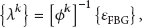
In FBG sensors, a Bragg grating is introduced to the core of a fiber [10]. If the broadband light source collides against the Bragg grating, a light with a particular wavelength, called the Bragg wavelength

As shown in Figure 1, the longitudinal strain of a beam member subjected to multiple loadings can be measured by typical FBG sensors attached to the face of the member. Especially from the aspect of SHM, the multiplexing technology in an FBG sensor makes strain-based SHM more reliable and practical because of the convenience with which such sensors can be managed and installed. A variety of applications can be found in the field of SHM, including building, civil, and infrastructure [11–15].
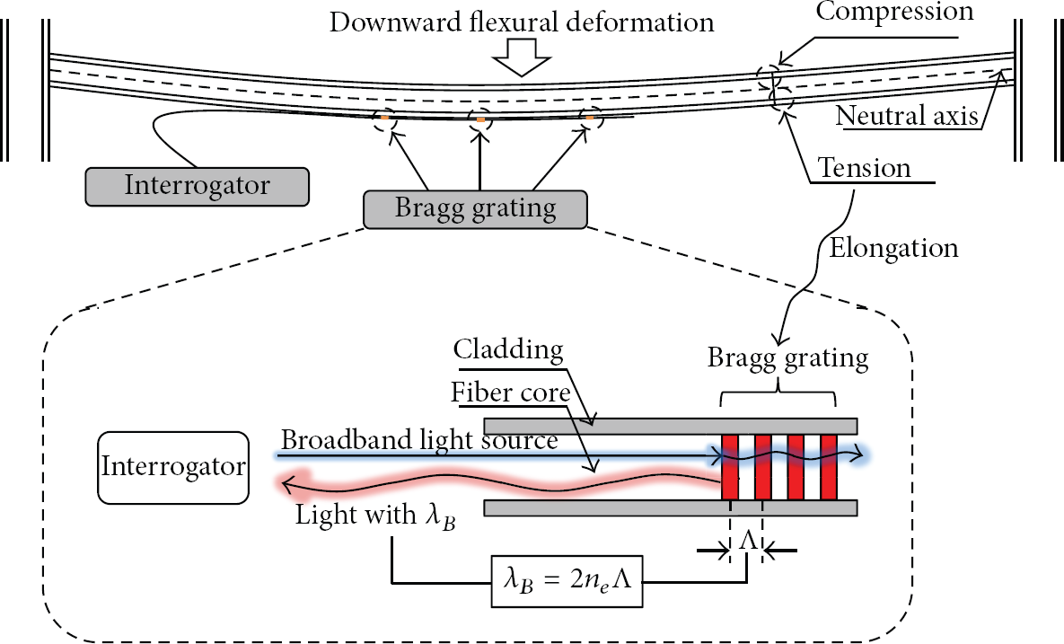
Measurement principle of the strain using an FBG sensor.
3. Maximum Strain Measurement Model
In this paper, the strain measurement model is presented to estimate the maximum strain of a beam structure using local strains measured from FBG sensors. For a beam structure subjected to multiple loading conditions simultaneously, the total strain at a specific point can be found by superimposing the strains due to separate loadings. However, to find the maximum strain of a beam structure instead of the strain value at a point, the deformed shape caused by the multiple loadings must be defined by superimposing the distribution shape of the strains along the length of a beam for each loading separately. The total strain at an arbitrary point in a beam structure can be estimated using the deformed shape.
3.1. Shape Function for the Distribution of Strains Caused by a Single Load
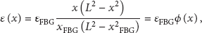
Based on general concepts in engineering mechanics, as shown in Figure 2, the longitudinal strain


Distributional strain-shape function

Distributional strain-shape function

Simply supported beam subjected to a linearly varying load.
As given in (5), the general form of
3.2. Superposition of Shape Functions Caused by Multiple Loadings
For a beam structure subjected to n different point loadings of 

Decomposition of the strain distribution caused by multiple loadings into individual effects.
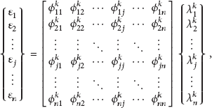
For the kth FBG sensor selected for the calculation of the factors, a system of n simultaneous equations in (7) can be expressed in matrix notation as follows:

3.3. Example Case: Simply Supported Beam Subjected to Three Types of Loads
To measure the strains in the beam structure subjected to a uniformly distributed load

Distribution of the strain-shape functions for a beam subjected to three different loadings.
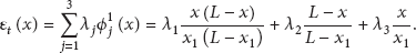
3.3.1. Strain-Shape Functions and Total Strain
The total strain distribution of the beams in Figure 4 is found by superimposing the strains caused by the three different loadings acting separately. If the first FBG sensor is selected to calculate the strain-shape functions and participation factors, the strain-shape functions for the three different loadings of 

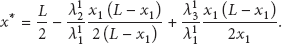
3.3.2. Maximum Strain
Using the total strain distribution along the length of a beam structure in (12), the location for the maximum strain caused by the three loadings can be found by setting the derivative of (12) equal to zero:

3.3.3. Simulation of the Example Case
To test the performance of the measurement model, the intensities of the three loadings
Using the values of the strains for FBG #1, #2, and #3, the participation factors of 
The distributions of the total strains and the strains caused by the three loadings are plotted in Figure 5, which illustrates that the strain values for FBG #1, #2, and #3 obtained from the structural analyses are identical to those estimated by the measurement model.

Composition of the total strain distribution.
The influence ratio 
The function of the total strain distribution and its components.

4. Application to Measurements of the Maximum Strain of a Steel Beam
The proposed measurement model could evaluate the maximum strain in beam structures subjected to multiple loading conditions using the strain-shape functions for various loadings, including point loading, distributed loading, and bending moment loading, as shown in Tables 1 and 2. The proposed measurement model was demonstrated for distributed loading and bending moment loading by a numerical simulation in Section 3.3. In this chapter, the experimental test is conducted to evaluate the performance of the proposed measurement model for the point loading condition.
4.1. Test Setup
In the bending test of the simply supported steel beam in Figure 6, a concentrated load was applied on the upper steel beam by a hydraulic jack. The load was increased in two steps, 7.4 and 12.9 kN. The concentrated load was split into two concentrated loads applied 1.25 and 3.25 m from the left end of the beam. The section of the beams was
Major specifications of the interrogator (IS 7000).

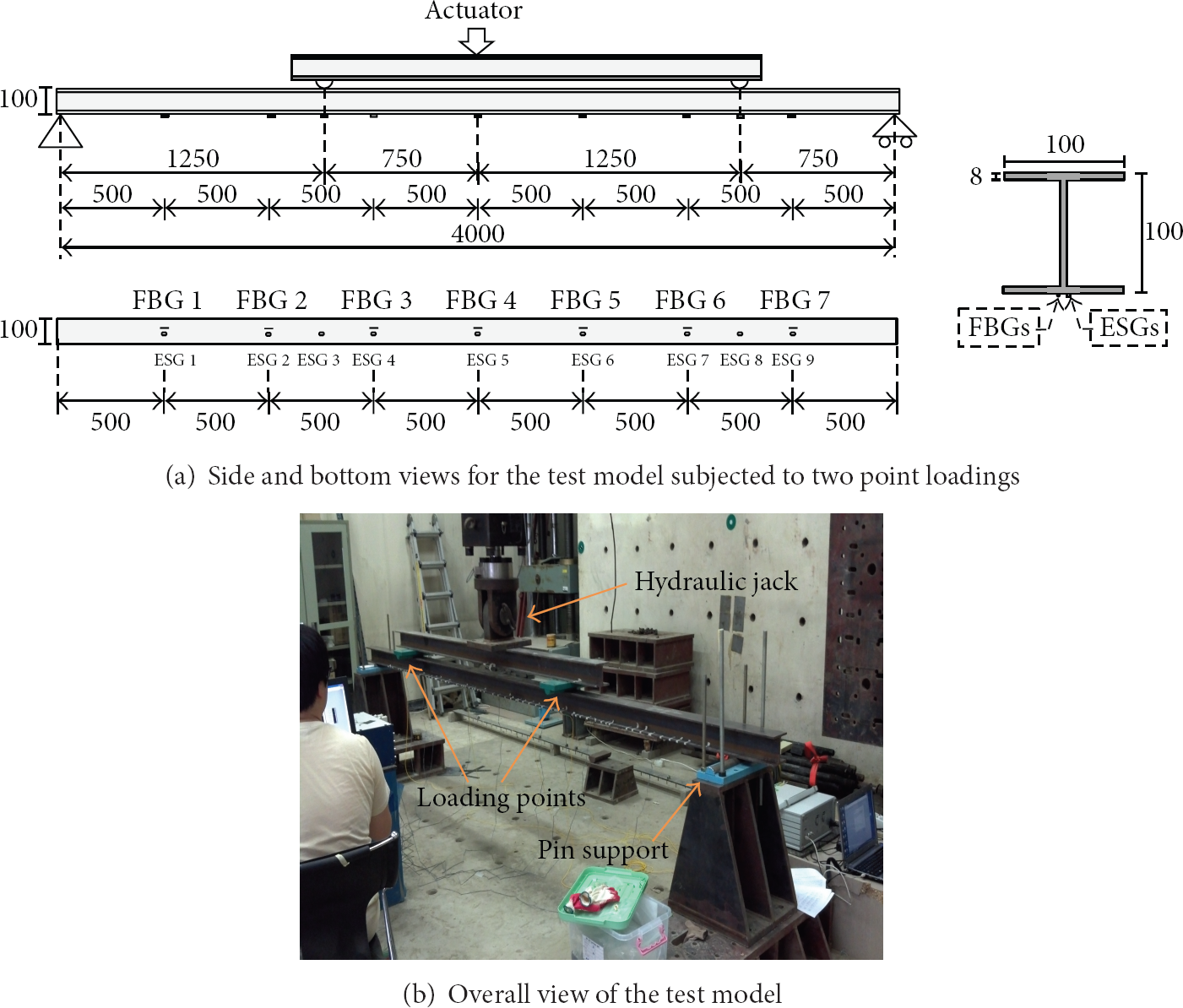
Test model setup.
4.2. Results
During the test, the beam deflected downward and tensile longitudinal strains occurred at the outer surface of the bottom flange. Before testing the measurement model, the strains obtained from the FBGs and ESGs were compared to verify the quality of the value by the FBGs. Table 5 indicates that the strain measured by FBGs could be assessed as reliable values for sensing beam members. The maximum difference between the two measurements was found to be less than 1.34% for each load step.
Measured strain by the FBG sensors and ESGs.

To measure the maximum strain of the test model subjected to two different point loads, two FBG sensors were required to estimate the maximum strain of the beam based on the model proposed in (6). Among the 21 possible combinations when choosing two of the seven FBG sensors without repetition, the combination of the first and second FBG sensors attached 0.5 and 1.0 m from the left end of the beam is not valid for the estimation because the matrix
To test the dependency on the selection of the locations for FBG sensors in the measurement of the maximum strain, all 20 FBG sensor combinations in Table 6 were used in the measurements. The numbers for the FBG sensors are shown in Figure 6(a). Figure 7 compares the estimated distributions of strains from the 20 FBG sensor combinations with the strains measured directly from the nine ESGs for each loading step. Furthermore, the dependency of the locations for the FBG sensors installed at the beam structure on the selection can be avoided using the measurement model in (5).
Number alignment of the combinations.


Estimated strain distributions from different combinations of FBG sensors for two.
To evaluate the performance of the measurement model, the relative error in the estimated strain distributions was calculated by

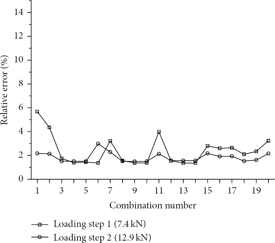
Relative errors of the estimated strain distributions.

Maximum strains estimated from the estimated strain distributions.
5. Conclusion
In this paper, a maximum strain measurement model for beam structures subjected to multiple loading conditions is developed by defining the strain-shape function and participation factors. The maximum strain in a beam is found by the sum of the strains caused by the different loadings acting separately. The strain-shape functions for various loading and support conditions are derived, and a system of equations is defined to calculate the participation factors. The influence of each loading on the value of the total strain can be identified using the influence ratio defined here.
The measurement model is applied to monitor the maximum strain in a 4 m long steel beam subjected to two concentrated loads. Seven FBG sensors and nine ESGs were attached on the surface of the bottom flange to obtain measurements during the test. The estimated maximum strain and distribution of strains along the length of the beam were compared with those obtained directly from the ESGs. The experimental results indicate good agreement between the strains that were estimated based on the model and the strains measured by the ESGs. Furthermore, the dependency of the locations for the FBG sensors installed on the beam structure on the selection can be avoided using the measurement model.
Footnotes
Acknowledgments
This research is supported by Grant (code #09 R&D A01) from High-Tech Urban Development Program funded by the Ministry of Land, Infrastructure and Transport.