
Abstract
The hydraulic accumulator is widely used for storing energy in hydraulic system, but it is a passive device; the flowrate and volume of hydraulic oil adjusted by the accumulator are not well adapted to working-condition changes or payload disturbances. A novel semiactive power-assisted unit (PAU), which is a flow valve-controlled accumulator virtually, is proposed. The flowrate and volume of the accumulator can be regulated by adjusting the spool-opening of the flow valve. The mathematical model of the semiactive PAU is deduced. Then the static characteristic and dynamic characteristic of the PAU are presented. The simulations of the proposed PAU applied in variable-speed electrohydraulic drive system are implemented. The results show the influences of PAU's main parameters on its performance.
1. Introduction
The hydraulic accumulator, which is used for storing hydraulic oil, is frequently applied in hydraulic drive systems. The applications focus on the five aspects: (1) Power-assisted unit [1–7]; (2) emergency power supply; (3) pressure-maintaining device; (4) pressure pulsation and shock absorber [8]; (5) pressure compensator [9]. The hydraulic accumulator is the most common used power-assisted device in hydraulic system. References [1–7] focus on the significant influence on the size of accumulators used for kinetic energy recovery of vehicles. Ho and Ahn proposed a new hydraulic closed-loop hydrostatic transmission energy-saving system with a hydraulic accumulator [1]. Puddu and Paderi analyzed the differences between the thermodynamic behaviour of real and ideal gases to determine their influence on the processes of compression and expansion of a gas-charged accumulator [2]. Chen et al. built the mathematical model of the characteristic parameters of parallel and series accumulator [3]. Midgley et al. discussed the modeling of hydraulic regenerative braking systems for heavy vehicles which consists of a high-pressure accumulator and a low-pressure accumulator, connected by two fixed-displacement in-wheel pump-motors [4]. To reduce the energy consumption and power installation requirements, Yang et al. studied the energy-regenerative hydraulic elevators with hydraulic accumulator [5]. Minav et al. analyzed the opportunities of storing energy recovered from an electro-hydraulic forklift truck [6]. Lin and Wang discussed the structure and performance of energy-regeneration system in the hybrid hydraulic excavator that combines the advantages of an electric and hydraulic accumulator [7]. Mamčic and Bogdevičius examined the structure of hydraulic accumulators to reduce pressure pulsations in hydraulic systems [8].
The bladder accumulator is generally chosen in power-assisted application for its simple structure and quick response. When it is used as a power-assisted device, it is designed according to the rated payload, in order to release oil and absorb oil efficiently in each working-cycle. However, once the working-condition or payload changes, the flowrate and volume adjusted by the accumulator cannot match the variations of working-condition and payload disturbances because of the accumulator's passiveness and uncontrollability. If the volume and precharged pressure of accumulator are fixed, the flowrate and volume adjusted by the accumulator only depend on the pressure difference between the accumulator and pump outlet. The uncontrollable feature of accumulator weakens its recycling and reusing function. The accumulator should adapt to the changes of working-condition or payload.
For the bladder accumulator, the parameters which can be changed include the port size, precharged pressure, and volume capacity. The port size and volume capacity are structural parameters, while the precharged pressure, belongs to working parameter. The adjustments of precharged pressure or volume capacity seem to be practical. But if the precharged pressure or volume capacity can be changed, the accumulator must be rebuilt with a complicated structure. The only way is to adjust the port size. A novel power-assisted unit, where a bladder accumulator connects in series with a flow valve, is proposed. The valve-controlled accumulator can control the spool-opening of the flow valve so as to adjust the flowrate and volume of hydraulic oil easily.
The variable-speed electrohydraulic drive uses a variable-speed electric-motor to drive a hydraulic constant-displacement pump, by adjusting the electric-motor speed to regulate the hydraulic-pump's output flowrate so as to meet the payload requirement. It is a typical load-sensitive hydraulic system with a well-known power-matching performance [10, 11]. The variable-speed electrohydraulic drive has been studied rapidly in two decades and gradually applied to injection molding machine [12], hydraulic elevator [5], wind turbine [13], shield machine, and other areas [14]. However, due to the large inertia of electric-motor and hydraulic-pump, the main disadvantage of variable-speed drive is slow response [15, 16]. To address this disadvantage, a flow valve was added into the variable-speed (variable-frequency) drive system to create a compound drive, where the frequency converter adjusts the electric-motor speed to satisfy the actuator's flowrate requirement and the flow valve controls the actuator's position or speed. The compound drive principle can improve control precision and low-speed performance, but it is helpless to improve the response when accelerating [15, 16].
The application of proposed PAU in variable-speed drive system attempts to improve responsiveness, especially when accelerating. This drive principle is distinguished from the compound drive by inclusion of an accumulator-based PAU. The electric motor-pump cannot always speed up as needed when accelerating, the PAU releases energy to improve the acceleration response. When the actuator needs to be decelerated but the hydraulic pump cannot slow down as needed, the PAU absorbs hydraulic oil. In other cases, the PAU is turned off.
This paper focuses on the structure, mathematical model, and static and dynamic characteristics of the semiactive PAU. And the relations between the PAU's main parameters to its releasing and absorbing performance are demonstrated by the application studies in variable-speed electrohydraulic drive system.
2. Principle of the Semiactive PAU
Figure 1 shows the principle of semi-active PAU used in open-type or closed-type hydraulic system. As shown in Figure 1 (a), the oil-in port of flow valve connects to the bladder accumulator, and the oil-out port connects to the pump outlet. The PAU is a semi-active control device essentially, because the flowrate and volume adjusted by accumulator depend on the pressure difference between PAU and pump outlet. If the PAU's inner pressure is bigger than pump outlet pressure, the PAU releases hydraulic oil. Otherwise, it absorbs hydraulic oil. So it needs pressure sensors to detect the inner and exterior pressure. As shown in Figure 1 (b), the oil-in ports of flow valves all connect to the accumulator; the other two ports connect to the pump outlet and inlet, respectively. The flow valve may be proportional flow valve, servo flow valve, or high-speed on/off valve. In this system, the proportional flow valve is applied.

Principle of the semiactive PAU. p a : gas pressure in the accumulator; p e : oil pressure in the PAU; p s : pump outlet pressure; p t : pump inlet pressure; Q a : flowrate adjusted by the accumulator; Q e : flowrate adjusted by the PAU; Q er : flowrate loss by the relief valve; V a : gas volume in the accumulator.
For the PAU used in open-type hydraulic system, the principle can be explained as follows. (1) When the actuator needs to be accelerated but the hydraulic pump cannot speed up as needed, if pe > ps, the PAU releases energy to improve the acceleration response. (2) When the actuator needs to be decelerated but the hydraulic pump cannot slow down as needed, if pe < ps, the PAU absorbs hydraulic oil. (3) In other cases, the PAU is turned off. The principle of PAU used in closed-type hydraulic system is similar to the above principle.
3. Modeling of the Proposed PAU
In the open-type hydraulic system, the modeling of proposed PAU is deduced as follows. Supposing that the nitrogen gas in the accumulator works in adiabatic state,
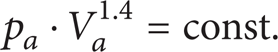
The derivation of (1) is

Then the oil volume discharged by the accumulator can be derived:
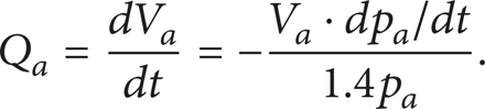
Similar to (1), the following can be deduced:

Since the initial pressure, pa0, and the initial gas volume, Va0, are known, using (3) and (4), the following can be deduced, where p e ≈ p a :

The proportional flow valve can be represented by
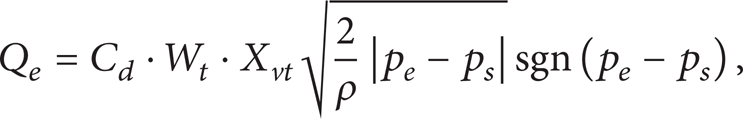
where C d is the spool constant, W t is the spool area gradient, X vt is the spool displacement, and ρ is the oil density.
Consider that

If the accumulator releases oil, Q e is positive. If the accumulator absorbs oil, Q e is negative.
The relation between the spool displacement and the control voltage of the flow valve can be simplified as

where u t is the control voltage, K tv is the gain coefficient, and ω t is the natural frequency.
Taking (8) into (6), and defining

The relief valve can be represented as
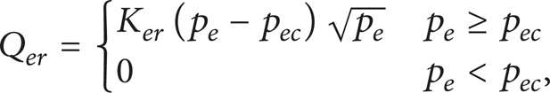
where K er is the gain coefficient and p ec is the cracking pressure.
Ignoring the leakage, the flow in the pipeline of PAU adheres to

where V e is the oil-tank volume of the PAU and E h is the bulk modulus of hydraulic oil.
The relief valve was used as a safety valve in the PAU, which is be closed in normal operation. So Q er can be supposed to zero:

The mathematical model of the proposed PAU can be described by (5), (9), and (12).
4. Static Characteristic Analysis
The static characteristic of proposed PAU is mainly embodied in its adjustable flowrate and volume of hydraulic oil. To get the static characteristics, assume that the pressure range of pump outlet is from p min to p max .
Supposing that the accumulator works at adiabatic condition, the following equations can be represented:

where pe0 is the precharged pressure, Va0 is the initial gas volume in the accumulator, and Va1 and Va2 are the maximum and minimum gas volume in the accumulator during the working process, respectively.
If pe0 < p min , the gas in the accumulator is always compressed. The adjustable oil volume by PAU can be represented by

If p min ≤ pe0 < p max , the accumulator is not always compressed. If p e < pe0, Va1 is equal to Va0, the adjustable oil volume by PAU is
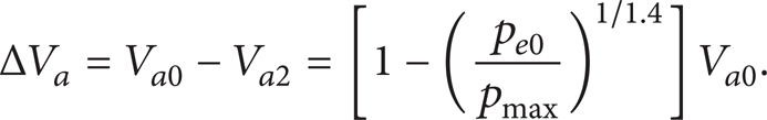
If pe0 > p max , the gas in the accumulator cannot be compressed. The PAU loses its adjustment function; ΔV a =0.
Figure 2 shows the diagram between the adjustable oil volume and accumulator precharged pressure. When pe0 equals p min , the adjustable oil volume reaches the maximum:


Adjustable volume of hydraulic oil.
In practical application, basically the larger the adjustable oil volume the better, so the volume capacity of accumulator should be as large as possible. The precharged pressure should be decided according to system pressure. If the system pressure changes periodically, the precharged pressure of accumulator should be equal to the minimum system pressure.
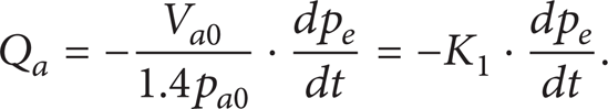
5. Dynamic Characteristic Analysis
The dynamic characteristic of proposed PAU is mainly embodied in the power-assisted speed. It is significant to the hydraulic system that the hydraulic oil volume discharged by the PAU is sufficient when the actuator is accelerating, which is beneficial to improve the acceleration response.
Without linearity in specific working point, it is impossible to dissolve and analyze the mathematical model of the PAU due to its strong nonlinear. Here suppose that the spool of the flow valve keeps in zero position (X vt = 0) and the gas in accumulator is full of the cavity (p a = p e ).
Define
The flow valve can be represented as
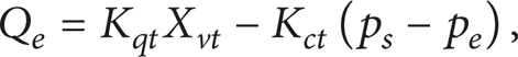
where K qt and K ct are the flow gain coefficient and flow-pressure coefficient, respectively.
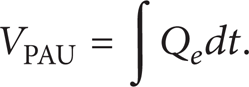
Define K2 = V e /E h . Equation (12) can be simplified as

The adjustable oil volume of PAU is
The Laplace transformations of (17) to (20) are implemented. And the transfer-function block diagram of the PAU is illustrated in Figure 3.
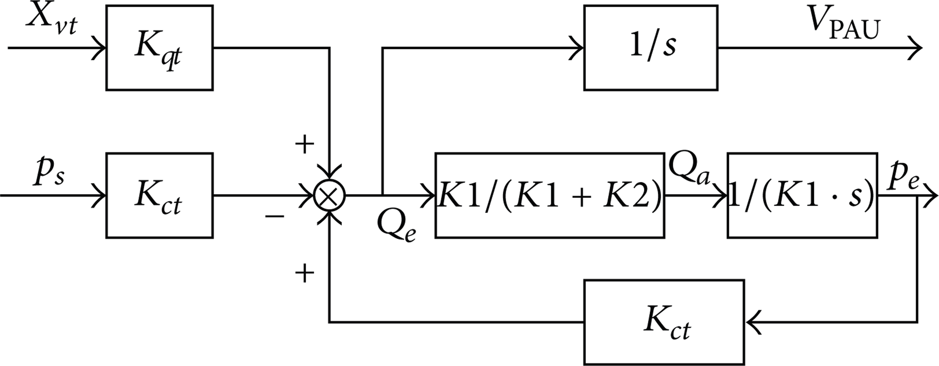
Transfer-function block diagram of PAU.
The adjustable oil volume of the PAU is presented as

where Ve0 is the initial oil-tank volume in the PAU.
Usually, Ve0/E h < < Va0/1.4pa0. And the spool displacement of flow valve keeps in zero position, X vt = 0. So (21) can be simplified as

Equation (22) is a typical one-order control system, where VPAU enlarges with the increase of Va0 and decrease of pa0. In this sense, the accumulator should be with a large volume capacity and a small precharged pressure.
The pressure of hydraulic oil in accumulator can be represented:

Because Ve0/E h ≈ 0, (23) can be simplified:

It can be seen that the pressure ascending-rate becomes slow with the increase of Va0 and the decrease of pa0. In the view of pressure response, Va0beingsmall and pa0beingbig are good to PAU.
For the flow valve, the transfer-function between VPAU and u t is
where K t is the total gain coefficient.
Frequently,

It can be seen that the flow valve with a large gain coefficient and a big natural frequency is good to the power-assisted performance of PAU.
6. Application in Variable-Speed Drive System
Figure 4 shows the principle of PAU applied in variable-speed drive system. There are two power sources, respectively, the main power source (the electric motor-pump) and the PAU (energy discharging and recycling device). The main power source is composed of a hydraulic constant-displacement pump and a variable-speed electric-motor (an electric-motor driven by a frequency converter).
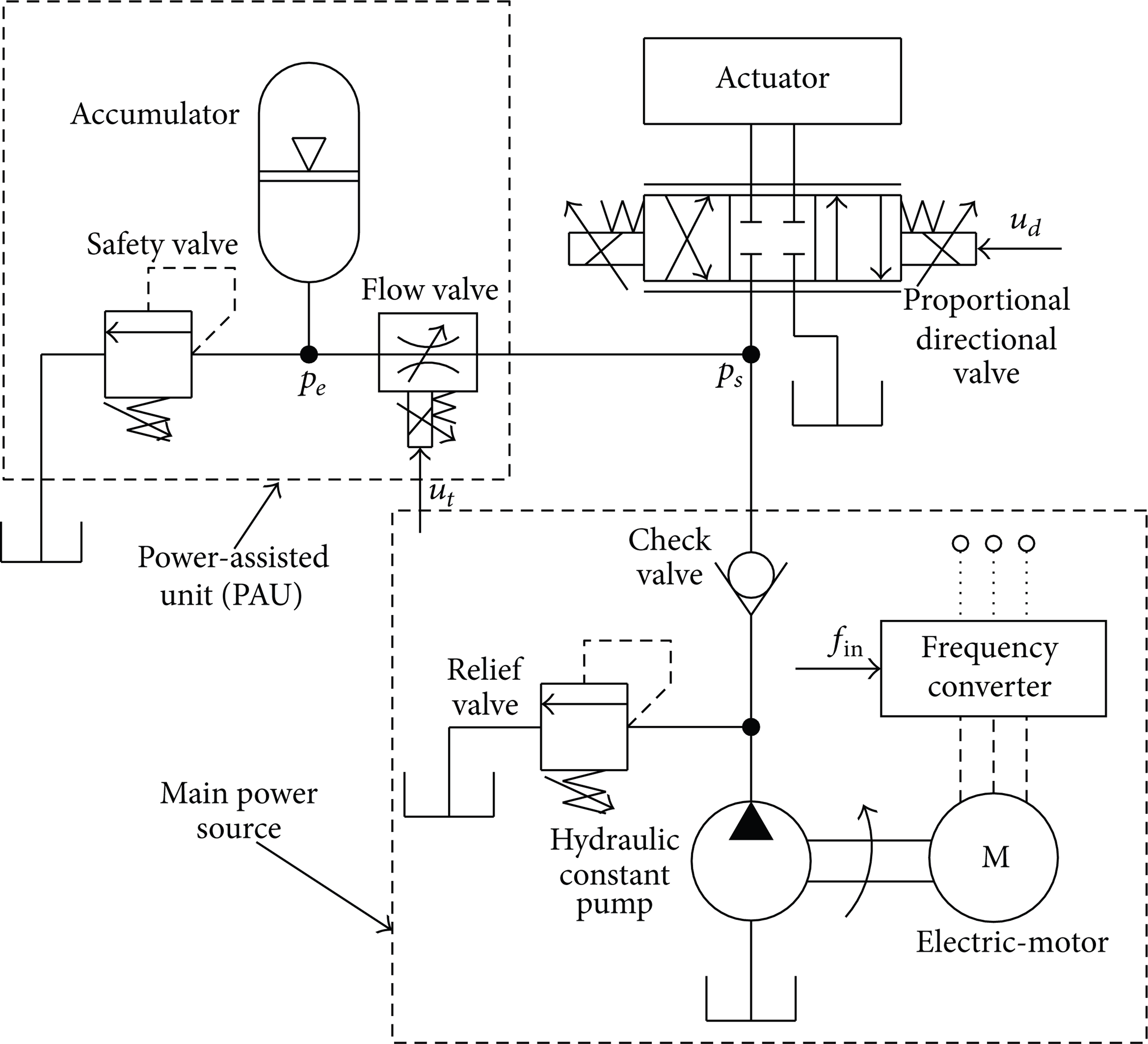
Principle of variable-speed drive system with a PAU.
As shown in Figure 4, the main purpose of directional valve is to accelerate the response when decelerating. The spool-opening of proportional directional valve can be decreased rapidly, thus speeding up the actuator's response when decelerating. In general cases, the proportional directional valve maintains its maximum spool-opening. In addition, the actuator's moving direction can be conveniently switched by using the directional valve. Therefore, the hydraulic-pump is only needed to rotate in one direction so as to deduce the impact caused by switching directions.
The mathematical model of variable-speed drive system with a PAU is deduced as follows.
The speed of variable-speed motor can be represented as

where K m and T m are the gain coefficient and time constant of variable-speed electric-motor, respectively. fin is the input frequency of frequency converter.
The output flowrate of pump is represented by the following:

where D p is the displacement of the hydraulic pump and k tc is the leakage coefficient.
The relief valve can be represented as

where K cr and p cr are the gain coefficient and cracking pressure of the relief valve, respectively.
In simulations, K m = 30 r/(min · Hz), T m = 3 s, D p = 40 mL/r, fin =50 Hz, p cr = 10 MPa, p ec = 15 MPa, k tc = 9.0 × 10⁻¹³ m4/kgs, E h = 700 MPa, and ρ = 850 kg/m3. The control signals of variable-speed electric-motor, flow valve, and directional valve are step signals. For the variable-speed electric-motor,

For the flow valve,

For the directional valve,

where u t max represents the maximum input voltage of the flow valve and u d max represents the maximum input voltage of the directional valve.
The MATLAB/Simulink is used for simulation for the developed model. Figure 5 shows the gain coefficient influence of flow valve to the released flowrate by the PAU. With the increase of gain coefficient, the flowrate curve becomes higher and narrower. It shows that the PAU becomes more capable to release hydraulic oil instantaneously. So it is beneficial to variable-speed drive system by enlarging the gain coefficient of flow valve.
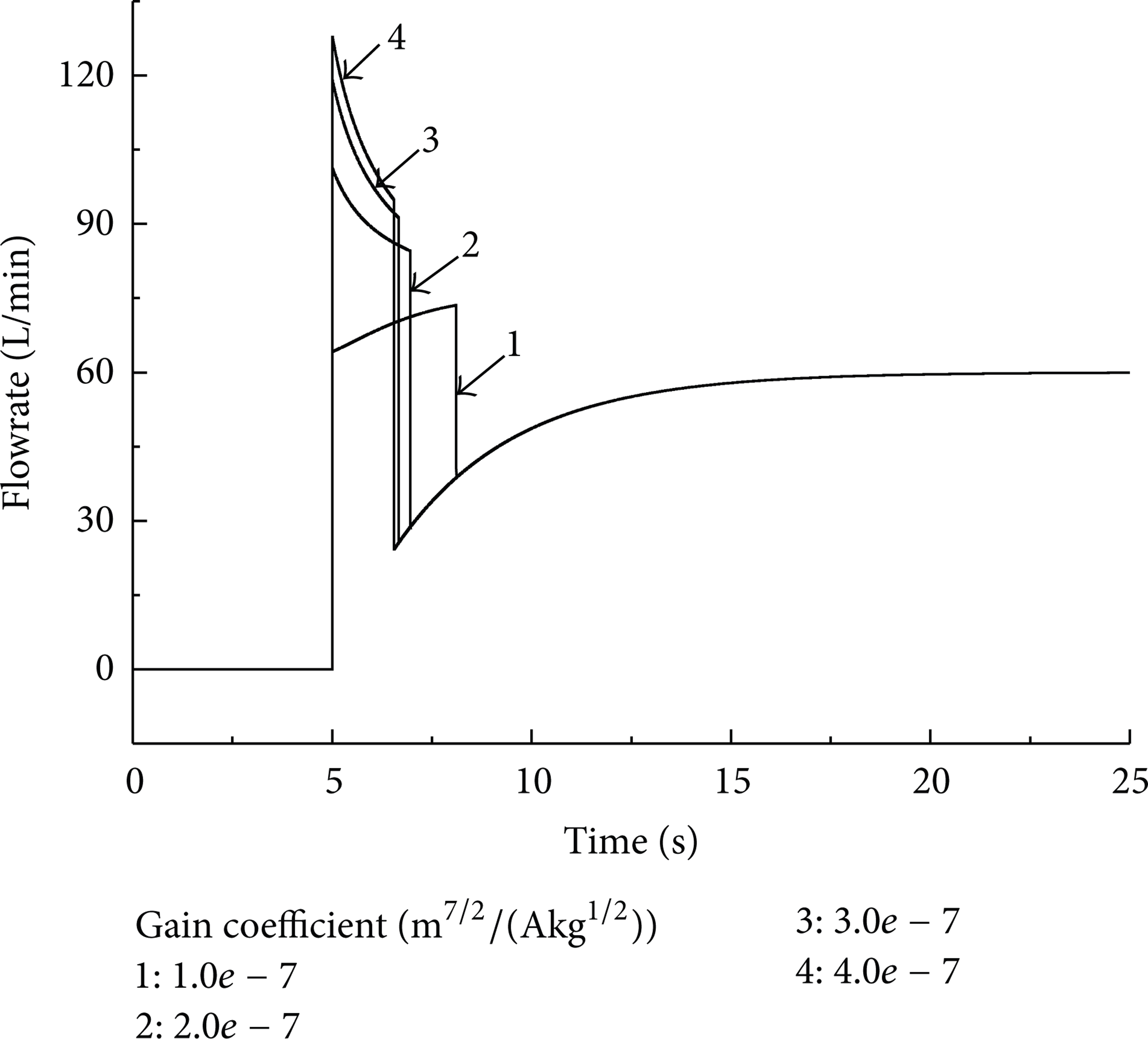
Influence of gain coefficient (pe0 = 5 MPa and Va0 = 6.3 L).
Figure 6 shows the influence of accumulator volume to the released flowrate by the PAU. With the increase of accumulator volume, the released oil volume increases. In practical application, it is better to use an accumulator with large volume.
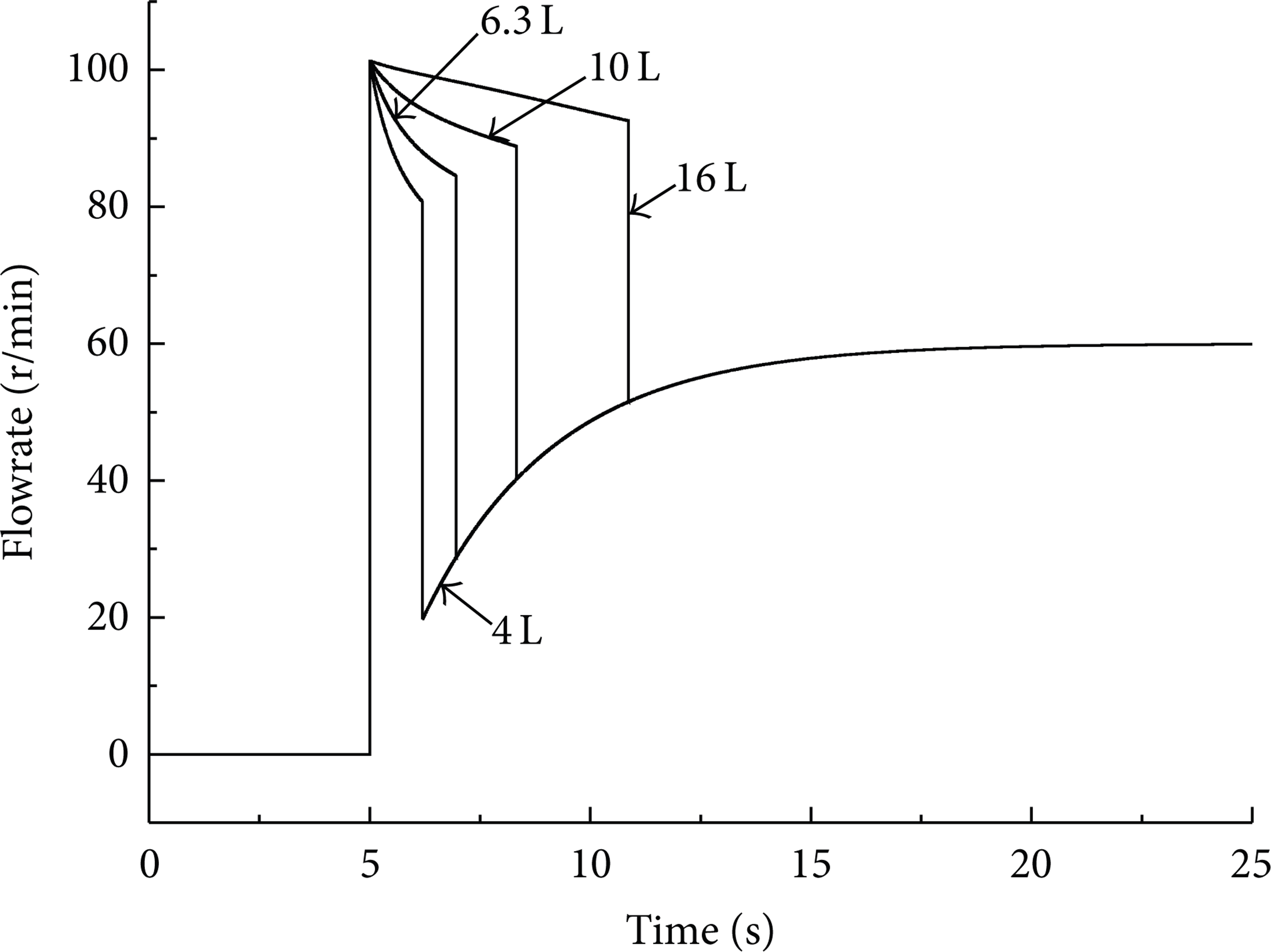
Influence of accumulator volume (pe0 = 5 MPa and K t = 2.0 e-7 m7/2/AKg1/2).
Figure 7 shows the influence of accumulator precharged pressure to the released flowrate by the PAU where the pump outlet pressure is 0 MPa. With the increase of accumulator precharged pressure, the released oil volume of PAU decreases. That is because the larger the precharged pressure is, the less oil can be stored in the PAU.

Influence of accumulator precharged pressure (p s = 0 MPa, Va0 = 6.3 L, and K t =2.0 e-7 m7/2/AKg1/2).
Figure 8 shows the influence of precharged pressure to released flowrate by the PAU where the pump outlet pressure is 5 MPa. When the precharged pressure equals to 5 MPa, the discharged oil volume of PAU is the most. And when the precharged pressure is 1 MPa, the discharged oil volume of PAU is the least. Though the stored oil in the PAU is maximum in 1 MPa, the PAU pressure decreases dramatically, so it discharges the least oil. When the PAU pressure is smaller than p s , it cannot release oil to accelerate the actuator any more. The most ideal situation is that the precharged pressure is equal to pump outlet pressure. In practical hydraulic system, the pump outlet pressure changes frequently. If the pressure range of pump outlet is between p min and p max , the precharged pressure of accumulator should be set to p min .

Influence of accumulator precharged pressure (p s = 5 MPa and Va0 = 6.3 L, and K t =2.0 e-7 m7/2/AKg1/2).
7. Conclusions
The proposed PAU is a semi-active device, which can control the flowrate and volume adjusted by the accumulator-based power-assisted unit with the aid of pressure sensors. The mathematical model as well as the static and dynamic characteristics of the proposed PAU are presented. And the attempt of proposed PAU applied in variable-speed drive system is carried out to improve the response especially when accelerating. The proposed PAU is very suitable to be used in variable-speed drive system. And the simulated results show that the precharged pressure and the volume capacity of accumulator, the flow gain coefficient, and natural frequency of flow valve are very important to the PAU's regulation performance. The volume capacity of accumulator should be as large as possible. The precharged pressure should be decided according to system pressure. If the system pressure changes periodically, the precharged pressure of accumulator should be equal to the minimum system pressure. The larger the flow gain coefficient as well as the natural frequency of flow valve the better to PAU's dynamic performance.
Footnotes
Acknowledgments
This research is supported by the National Natural Science Foundation of China (Grant no. 51205099) and Zhejiang province key science and technology innovation team (Grant no. 2010R50003).