
Abstract
Pear-shaped casing swage (PCS) repair technology is highly efficient in repairing deformed casing and the value of repairing force is a very important parameter for designing and optimizing the casing swage and structure parameters. A new three-dimensional simulation analysis of casing swage in the well and the finite element analysis (FEA) model of 7′′ API deformed casing and PCS are established based on the elastic-plastic mechanics, the finite element theory, and application of numerical simulation analysis for the actual process of repairing deformed casing. According to the model, the repairing force required to repair the deformed casing is obtained; furthermore, the correlation between the repairing force and confining pressure is obtained. Meanwhile, the repairing test of deformed casing was performed by using PCS in the lab. Experimental results are consistent with simulation results. It indicated that the mechanical model can provide theoretical guidance for design and optimization of the structure of tool and reshaping technological parameters.
1. Introduction
Casings of many oil and gas wells at home have been in deformation [1] due to the creep of mudstone, shale [2], water injection [3], and corrosion factors after the production for a long period of time, which restricts the application of stimulation and perforation. For example, the casings in Long-gang 001-1, Long-gang 001-2, Long-gang 39, Long-gang 13, Pu-guang 204-2H wells in Sichuan and Chongqing gas fields, the Yingshen 1 well in Tarim oilfield, and the TK1127 well in Tahe oilfield in Xinjiang were destroyed by creep and plastic flow of salt rock. Those failures pose a serious threat to the safety of oil and gas field.
In order to restore the normal production of oil and gas field, many repair technologies [4] have been proposed at home and aboard. Among them, the PCS repair technology (it belongs to impact truing technology) is often utilized to repair the deformed casing of oil and water wells, and the repair technology reaches the purpose of expanding casing by exerting impact load on deformed casing based on the impact theory.
However, the current PCS repair technology sometimes leads to many problems [5–7] (e.g., the smaller repairing force cannot reach the purpose of repairing and the larger repairing force causes great damage of cement sheath and continuing damage to casing, or the sticking accidents) because the size of repairing force cannot be known or controlled accurately. At present, scholars at home and abroad have done many studies in the field of casing failure, which mainly includes the studies about the mechanism of casing failure [8, 9], casing failure detection technology [10], repair technologies [11–15] (such as grind press plastic technology, PCS technology, casing patch technology, and solid expandable tubular technology), and preventive measures [16].
Besides, the researches about the expandable technology for casing repair have been done in detail by many scholars. For example, Binggui et al. [17] established a solid expandable tubular (SET) finite element model to analyze the stress, strain, and residual stress of SET and to analyze the internal tube changes. Mack and Shell Intl [18] designed a laboratory program to study the effects of tubular expansion and method of tubular expansion upon the mechanical properties of casing. Al-Abri [19] employed the analytical model and numerical solution to predict the force required for expansion and the length and thickness variations induced in the tubular due to the expansion process under different expansion ratio. Experiments have also been conducted for tubular expansion to validate analytical and numerical solutions.
It is known that many researches about mechanism of casing failure and solid expandable tubular technologies have been done. However, the study about PCS technology is not enough or cannot solve problems completely, especially the research about the working mechanics. Hence, in this paper, a new three-dimensional simulation analysis of casing swage in the well and the finite element analysis (FEA) model of 7′′ API deformed casing and PCS are established based on the elastic-plastic mechanics, finite element theory, and application of numerical simulation analysis for the actual process of repairing deformed casing. With the aim of validating the accuracy and reliability of this model, the repairing test of deformed casing by PCS was performed. The test results and simulation results provided powerful guidance for the determination of designing and construction parameters of this tool.
2. An Overview of Pear-Shaped Casing Swage
2.1. The Basic Structure
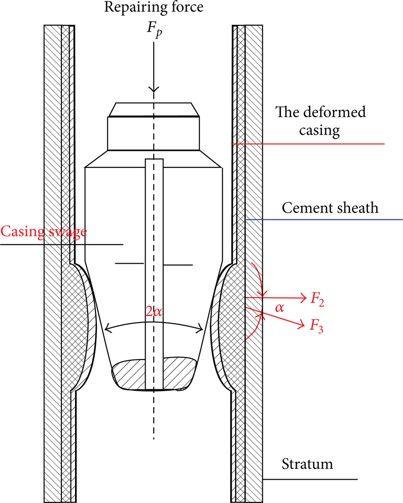
In Figure 1, the outer layer is stratum, the middle layer is cement sheath, the inner layer is deformed casing, the PCS is in the center of deformed casing, the cone angle of casing swage is 2α, F3 is the tangential force, F2 is the lateral component, and F P is the repairing force.
The structural drawing of pear-shaped casing swage.
2.2. Working Principle
When the repairing force F P is exerted on the pear-shaped casing swage, the lateral component F2 is generated between the work face of PCS and the part of deformed casing as in Figure 1. The lateral component expands the deformed area of casing. The casing swage is placed to the deformed area of casing by using PCS to repair the deformed casing. Next, the PCS impacts and expands the deformed casing by relying on the repairing force applied on the casing swage. Finally, the purpose of repair is achieved by the reciprocating motion of PCS in the center of deformed casing.
3. Repairing Test of Deformed Casing
In order to validate the accuracy and reliability of this finite element model in this paper, the repairing test of deformed casing by PCS was performed under zero confining pressure. The structure parameters of PCS are the same as parameters of the PCS used in finite element model established in this paper. Geometrical and mechanical parameters of the deformed casing are shown in Table 1.
The geometric and mechanical parameters of deformed casing.

3.1. The Main Experimental Equipment and Methods
The reshaping test system mainly consisted of YE-2533 static strain indicator, YS32-500 universal hydraulic machines, upper fixture, bottom fixture, and the crossover sub with a strain gage, as shown in Figure 2. The upper and bottom fixtures were used to fix the PCS and deformed casing, respectively. The universal hydraulic testing machine was used to impose repairing force which pushed the PCS reciprocating movement in the middle of deformed casing. Static strain indicator was used to measure the compressive strain on the crossover sub and the deformation rule of deformed casing during the repairing process. Therefore, the repairing effect can be obtained in the repairing process according to the deformation rule of deformed casing. Based on Hooke's law, the compressive strain, and the geometry dimension of the crossover sub, the repairing force F P of PCS can be given:

where E is Young's modulus of casing (MPa), σ is the compressive stress (MPa), and A is the cross-sectional area of crossover sub (m2).

The repairing process and experimental equipment.
3.2. Test Results and Analysis
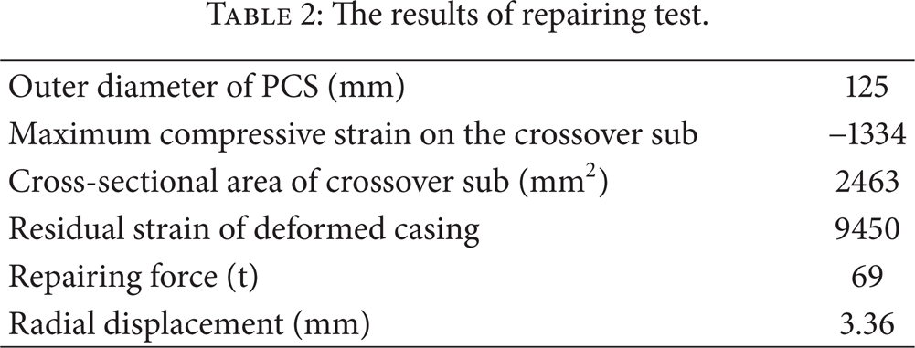
The deformation rule of deformed casing has been tested according to the measured strain in the repairing process, as shown in Figure 3. Figure 3 shows that the larger plastic deformation of deformed casing occurred and the residual microstrain was equal to 9540 (microstrain) in the repairing process, as indicated in Table 2. Therefore, it indicated that a good effect has been achieved in the repairing process. In addition, the maximum compressive strain (ε = – 1334) on the crossover sub was measured in the repairing process, as shown in Table 2. The expanding radial displacement (residual deformation) of deformed casing measured by micrometer is equal to 3.36 mm after being repaired. The repairing force (F P = 69 t) has been obtained according to (1), and the parameters are listed in Table 2.
The results of repairing test.

The deformation rule of deformed casing in the repairing process.
4. Finite Element Model
4.1. The Geometric and Mechanical Parameters of Material
The PCS mainly includes guide cone and working face. The maximum diameter of PCS is 125 mm; its cone angle is 12 degree, as shown in Figure 4. The PCS is regarded as rigid body and its deformation is not considered in the process of simulation.
The cross section of repaired C110 casing is oval; its short axis diameter and long axis diameter are 120 mm and 185 mm, respectively. Its wall thickness and axial length are 12.65 mm and 500 mm. Its elasticity modulus and Poisson's ratio are 210 Gpa and 0.3, respectively. Based on the stress-strain curve of tensile test, as shown in Figure 5, the mean yield strength (830 MPa) of deformed casing can be obtained, as shown in Table 1. The coefficient of friction between deformed casing and PCS is 0.1.
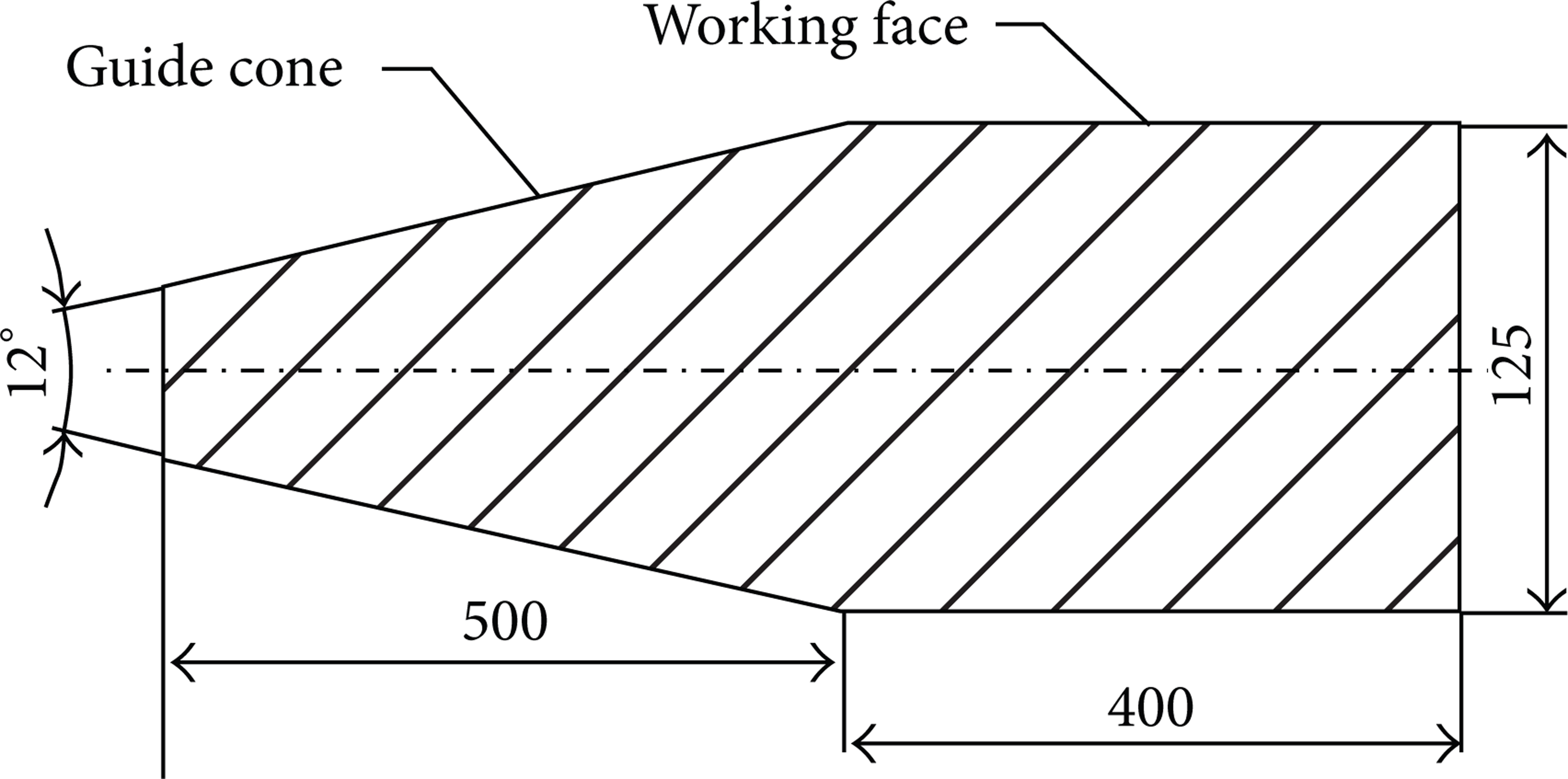
The main dimensions of pear-shaped casing swage.
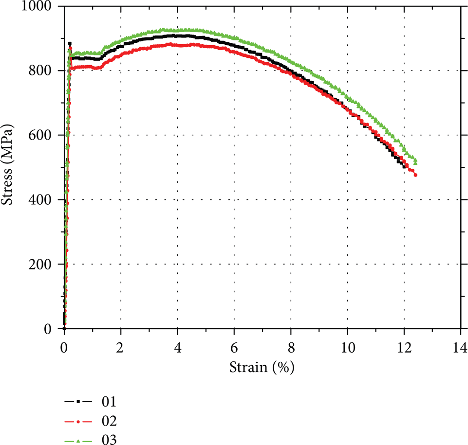
Stress-strain curve of deformed casing.
4.2. Establishment of Finite Element Model
Parametric geometry model of PCS and deformed casing was established by using the finite element analysis software (ABAQUS 6.9). So, the repairing process of deformed casing can be studied by changing the geometric and mechanical parameters of this finite element model. The 8-node linear reduced integration hexahedral solid element (C3D8R) was adopted to divide the finite element model because the type of element has three main advantages: first, it is suitable for the 3D solid model; second, it has precise calculation result of displacement; last but not the least, it could save a large amount of computing time. The axial length of deformed casing is divided into 100 equal parts, the radial thickness is separated into 6 equal parts, and the circumferential length is divided into 39 equal parts as shown in Figure 6 (b). The mesh size which increases gradually from inner wall and outer wall of deformed casing is different. The finite element model of deformed casing presented in Figure 6 incorporated 23,400 elements.

3D solid model of pear-shaped casing swage and deformed casing.
Only one-quarter of the deformed casing's cross section is used to simulate the repairing process of deformed casing while considering the symmetry of the deformed casing as shown in Figure 6 (b). To observe the stress and displacement distribution at the deformed casing, three-dimensional hexahedral element was chosen to build the model as shown in Figure 6 (b). In addition, the casing swage and deformed casing are regarded as rigid body and deformable body, respectively. According to the above mechanical model and material parameters, 3D solid model is used to simulate the repairing process of deformed casing by PCS and the model consists of PCS and deformed casing, as shown in Figure 6.
Based on this model, the repairing process is simulated by slow reciprocating motion of PCS in the center of deformed casing. The elastic and plastic deformation need to be considered simultaneously because the maximum Von Mises stress will be greater than the yield limit of deformed casing. So, in the process of simulation, the elastic stage is analyzed using Hooke's law, Von Mises yield criterion is adopted, and the plastic stage is analyzed using the Prandtl-Reuss constitutive equation. Based on that method, the repairing process of deformed casing mainly includes four stages (precontact, initial contact, repairing process, and after being repaired) which will be analyzed one by one in detail.
4.3. Boundary and Constraint Conditions
Symmetry constraint is applied to both sides of deformed casing, as shown in Figure 6 (a).
A fixed displacement constraint along the axial direction of casing is applied to the bottom of the deformed casing but the casing can expand along the radial direction during the repairing process with the aim of obtaining the repairing force; one reference node is predefined at the bottom of the deformed casing.
The uniform confining pressure (0 MPa, 5 MPa, 10 MPa, 20 MPa, and 30 MPa) is applied to the outer wall of deformed casing in sequence; uniform confining pressure is used to simulate the repairing process of deformed casing under different formation pressure.
The downward displacement of PCS along the axial direction of casing is equal to 1 meter larger than the axial length of deformed casing, as shown in Figure 6 (c).
The PCS is also constrained from rotation about its own axis.
The analytical method and model which are used to simulate the repairing process are the same under different confining pressure. In addition, the confining pressure is equal to zero in the physical experiment performed in this paper. Hence, this paper takes simulation of the repairing process under the condition of zero confining pressure as the major study object while only the simulated results are given under the different confining pressure condition for providing theoretical basis for the deformed casing repair in the different formation depth.
5. Simulation Results and Analysis
5.1. Simulation Results and Analysis under the Condition of No Confining Pressure
The radial deformation of deformed casing is shown in Figure 7 in the process of deformed casing repaired by 125 mm PCS. The Von Mises equivalent stress is shown in Figure 8 in the process of deformed casing repaired by 125 mm pear-shaped casing swage. According to the reacting force on the predefined reference node at the bottom of the deformed casing, the repairing force (63.5 t) has been obtained in the repairing process.

Radial displacement distribution of deformed casing at different stages.
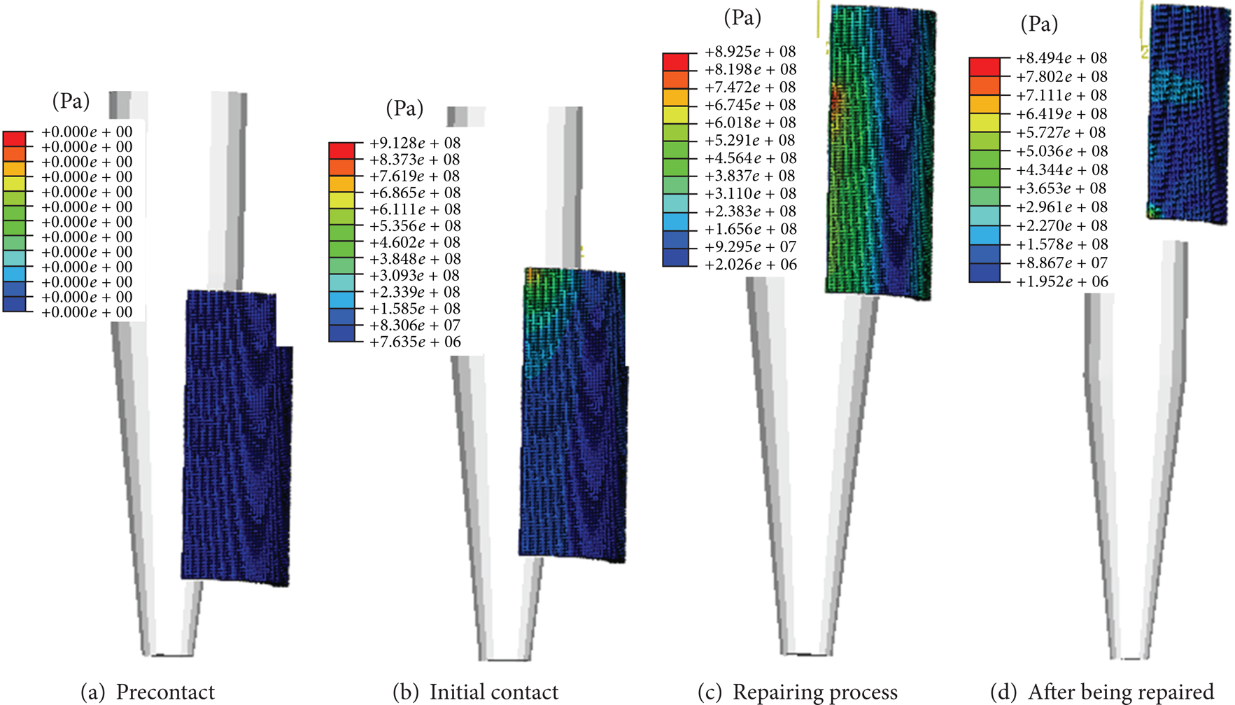
Von Mises equivalent stress distribution of deformed casing at different stages.
From Figures 7 and 8, we can observe that the repairing process of deformed casing mainly includes four stages (precontact, initial contact, repairing process, and after being repaired). The deformation, Von Mises equivalent stress, and the repairing effect of deformed casing can be seen clearly from those four stages.
In the first stage, it can be seen from Figures 7 (a) and 8 (a) that the Von Mises equivalent stress and radial displacement of deformed casing are equal to zero.
In the second stage, it can be observed from Figures 7 (b) and 8 (b) that the Von Mises equivalent stress and radial displacement of deformed casing reach maximum when the PCS initially contacts the deformed casing. The maximum (912 MPa) of Von Mises equivalent stress is considerably larger than the yield strength (830 MPa) of deformed casing. It indicates that the plastic deformation of deformed casing occurs and the repairing effect of contact region is good.
In the third stage, it can be noticed from Figure 8 (c) that the maximum (892.5 MPa) of Von Mises equivalent stress is also lager than the yield strength (830 MPa) of deformed casing. Similarly, it is seen from Figure 7 (c) that the plastic deformation of deformed casing occurs and the repairing effect of entire deformed casing is good in the repairing process.
In the fourth stage, it can be concluded from Figure 8 (d) that the maximum of the residual stress of deformed casing reaches up to 849.4 MPa; the maximum of unilateral expanding radial displacement (residual deformation) of deformed casing is equal to 1.81 mm after being repaired and the total radial displacement of deformed casing is equal to 3.62 mm according to the symmetry.
5.2. Simulation Results and Analysis under the Confining Pressure
The same PCS is used to simulate the repairing process of deformed casing, as shown in Figure 9, and the geometric and mechanical parameters of deformed casing are shown in Table 3. The repairing process of deformed casing is simulated by using the same finite element model under different confining pressure (0 MPa, 5 MPa, 10 MPa, 20 MPa, and 30 MPa). Similarly, according to the reacting force on the predefined reference node at the bottom of the deformed casing, the repairing forces have been obtained in the process of repairing under different confining pressure, as shown in Figure 9 and Table 3.
The repairing force obtained by FEA under different confining pressure.


The correlation between the repairing force and confining pressure.
It can be seen from Table 3 and Figure 9 that repairing force increases with the increase in confining pressure. The linear relation (F = 3.02483P + 66.11724) between the repairing force and confining pressure is obtained by analyzing and fitting those data, as shown in Figure 9. Based on that relation, the repairing force required to repair the deformed casing under different confining pressure can be determined accurately so that it can provide powerful guidance for the designing and construction parameters of the pear-shaped casing swage.
5.3. Summary
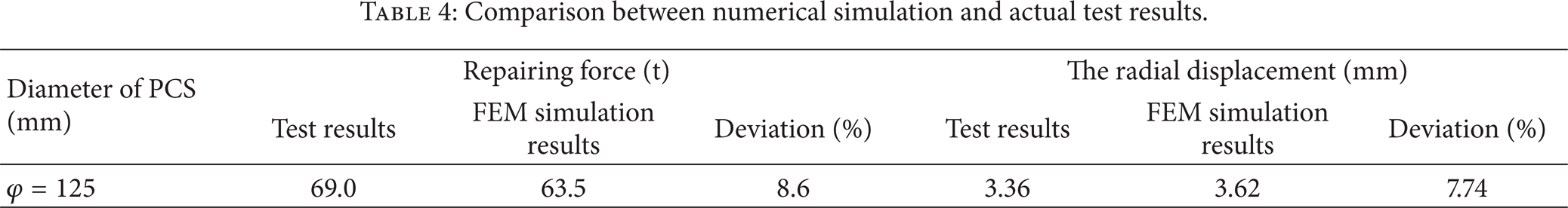
The maximum of Von Mises equivalent stress of deformed casing is larger than the yield strength and the plastic deformation occurs during the repairing process. The maximum of residual stress of deformed casing reaches up to 849.5 MPa and the total expanding radial displacement (residual deformation) of deformed casing is equal to 3.62 mm after being repaired. The repairing force required to repair deformed casing is equal to 63.5 t under the condition of zero confining pressure as shown in Table 4. All of them suggested that the repairing effect is good.
Comparison between numerical simulation and actual test results.
The repairing process of deformed casing has been simulated by using the finite element model under different confining pressure (0 MPa, 5 MPa, 10 MPa, 20 MPa, and 30 MPa). Similarly, the repairing force has been obtained under different confining pressure and the repairing force increases with the increase of confining pressure. The relation (F = 3.02483P + 66.11724) between the repairing force and confining pressure has been obtained by fitting and analysis of the obtained experimental data.
The numerical simulation results and the actual test data were compared as shown in Table 4. It can be observed from Table 4 that the repairing force (69 t) obtained by repairing test is close to the simulation results (63.5 t) and the deviation is 8.6%, which is acceptable. The expanding radial displacement (3.36 mm) obtained by repairing test is close to the simulation results (3.62 mm) and the deviation is 7.74%, which is acceptable. It is considered that the experimental results are in excellent agreement with the simulation results of FEA and the finite element model and analysis results are accurate and reliable.
6. Conclusions
The repairing test of 7′′ API deformed casing was performed by using pear-shaped casing swage. The repairing force, expanding radial displacement (residual deformation) of deformed casing, and the deformation law of deformed casing in the repairing process were obtained according to the repairing test.
Based on the elastic-plastic mechanics and finite element theory, three-dimensional finite element analysis (FEA) model was established with the aim of studying the repairing process of deformed casing by pear-shaped casing swage. According to the model, the repairing force required to repair the 7′′ API deformed casing was obtained and the linear correlation (F = 3.02483P + 66.11724) between the repairing force and confining pressure was obtained. So this model can provide theoretical basis for the deformed casing to repair in different formation depth.
The accuracy and reliability of the proposed finite element model have been validated through a very careful comparison with test data. It indicated that the results of the repairing test and the finite element model can provide powerful guidance for designing and constructing parameters of the pear-shaped casing swage.
Footnotes
Acknowledgment
The authors are thankful to the National Natural Science Foundation of China (nos. 51074135, 51274170, and 51004084) for providing the financial assistance.