
Abstract
This paper reviews the research of monitoring technologies for bolted structural connections. The acoustoelastic effect based method, the piezoelectric active sensing method, and the piezoelectric impedance method are the three commonly used to monitor bolted connections. The basic principle and the applications of these three methods are discussed in detail in this paper. In addition, this paper presents a comparison of these methods and discusses their suitability for in situ or real-time bolt connection monitoring.
1. Introduction
Bolts are important elements for detachable assembly of components in structures and machines. Bolts provide the required axial or preload forces on the components. A bolt's axial load or preload has to be carefully controlled to ensure the safety and reliability of structures. Insufficient preload or excessive preload is a frequent cause of bolt joint failure [1, 2]. Monitoring the preload of high-tension bolts is critical in maintaining the strength and safety of bolted joints in engineering structures. There are many ways to indirectly measure bolt tension.
Current practice relies on the torque wrench technique. However, with this technique, the torque load dissipates due to the friction between the bolt threads and the nut, which prevents accurate measurements of the axial load. The torque wrench method was reported to show large intrinsic errors in bolt tension measurement by up to 50%. This typically occurs since the torque applied to fastened bolts is consumed mostly by friction—only 10–15% of the torque is converted to the tension in the bolts. Friction consumes about 90% of the torque, with 50% dissipated in the bolt head and 35% in the bolt threads. Additionally, the friction varies so widely from bolt to bolt that errors of 50% are common, even with a perfect torque control. This complication leads to overconservative designs for safety, which in turn increases both weight and cost of bolted connections [3].
An effective way to measure the bolt strain is using a standard resistance strain gauge mounted to the body of the bolt. This method results in an accurate bolt-strain measurement. Another method, which is used when both sides of the bolt are accessible, involves a caliper to directly measure bolt elongation. However, in many instances, this is impossible since the bolt elongation is so small that it is difficult to measure it accurately. Please note that this method is not suitable for in situ monitoring.
An ultrasonic method is considered as a valuable method to measure bolt axial load, which is based on the acoustoelastic effect that the velocity of the ultrasonic wave propagated along the bolt depends on the axial stress.
Interface contact characteristics change with the preload. With the active piezoelectric sensing technique, the variation of the interface contact characteristics can be monitored by the ultrasonic signal generated by the piezoelectric transducer; thus, the bolt connection status can be monitored. This active sensing method has a great potential for in situ/real-time monitoring.
Vibration-based damage assessment of bolted structures has also been accomplished using the transmittance function method as described by Caccese et al. [4]. The vibration-based health monitoring strategy has been developed by Razi et al. to detect the loosening of bolts in a pipeline's bolted flange joint, and the empirical mode decomposition is applied to establish an energy-based damage index and several damage scenarios simulated by loosening bolts through adjusting the applied torque were investigated [5]. Zadoks and Yu [6] investigated the self-loosening behavior of bolts under transverse vibration. Pai and Hess [7] studied the loosening of threaded fasteners due to dynamic shear loads with this traditional dynamic method. Vibration-based damage assessment of bolted structures is a feasible method, and common vibration test equipment can fulfill the purpose [8]. However, for the bolt loosing detection, the subsequent treatment of vibration signal is complex and for the complicated bolted structures, it is difficult to detect the bolt looseness status and loosened bolt position based on this method [9–11].
This paper reviews the measurement technologies for bolt connection status. Three main methods for bolted structure monitoring are discussed in this paper. These three methods are acoustoelastic effect based method, the piezoelectric active sensing method, and the piezoelectric impedance method. This paper presents the basic principle and the applications of these three methods and also discusses their suitability for the in situ bolt connection monitoring.
2. Acoustoelastic Effect Based Methods
A bolt's acoustoelastic response changes with its axial stress. The following three properties associated with the acoustoelastic response can be used to compute the axial stress level: (1) the transit time ultrasound along the bolt (portable instruments are commercially available), (2) the transit time ratio between longitudinal and shear waves propagating along the bolt (or mode-converted shear wave at the lateral surface), and (3) the mechanical resonance in the bolt. In this section, three different methods, which are, respectively, based on these three properties, are reviewed.
2.1. Time-of-Flight Method
The time-of-flight (TOF) in the bolt, measured by the sing-around technique with an ultrasonic probe set on the bolt head, is obtained from the time difference between the reflecting waves in the first round trip and the second round trip.
The propagation of ultrasonic waves is sensitive to both residual and applied stresses in materials. The elastic wave propagation depends on the direction and polarization of the waves as well as the direction of the applied stress. Because of these effects, the velocities of ultrasonic waves depend on different stress states in the material.
In the case of plane waves in a homogeneous and isotropic material, the velocities of longitudinal and transverse waves, which propagate in the same direction as the applied stress, can be written in their first-order approximation as [12, 13]


For a bolt subjected to an axial load, certain parts of the total length are partially stressed or unstressed. To take this fact into account, assume that the initial bolt length is the sum of the effective length


Model of an axially loaded bolt.
Suppose that

Combining (1a), (1b), and (3) results in


From (5), it can be seen that the bolt axial stress or force can be determined once the time-of-flight of ultrasonic waves under stressed and unstressed states is measured. Once the relationship between F and
Yasui and Kawashima [15] used a broadband normal incidence transducer in the measurement of the bolt load, which excites and receives simultaneously a 10 MHz longitudinal wave and a 5 MHz transverse wave. Hirao et al. [16] used a noncontacting shear-wave electromagnetic acoustic transducer (EMAT) which generates and detects the shear wave propagating in the axial direction of the bolts. Both experiments show a good linear relationship between the load and the TOF or the signal phase.
The variation of ultrasonic velocity in the range of actual stress acting in the bolt is very small, and, as a result, experiments require precise and accurate measurement of the ultrasonic velocity. The phase detection method [17] is adopted for the precise measurement of TOF instead of the conventional pulse-echo technique that is sensitive to noise. 5 MHz ultrasonic transducers are located on the top and bottom of the sample to measure the TOF and the experiment results show that the ultrasonic velocity decreases linearly corresponding to the stress increase.
Since most of the TOF methods use relatively high-frequency (about 5 MHz to 10 MHz) ultrasonic waves, the excitation waveform of the emitter which corresponds to a 230 KHz frequency sine signal truncated by a hamming window was used to measure stress level in the prestressed steel strand [18]. A guided ultrasonic wave for monitoring the stress levels in seven-wire steel strands (15.7 mm in diameter) was proposed and investigative experiment shows the potential and the suitability for evaluating the service stress levels in the prestressed seven-wire steel strands.
Because the time-of-flight in the bolt is only in the range of tens of nanoseconds, the data acquisition process requires a high sampling rate for the data acquisition system (1.0 ns for 1 GS/s in equivalent sampling rate) and thus increases the cost. Most references used oscilloscopes to capture the signals; however, such devices are not suitable for the in situ bolt health monitoring.
2.2. Velocity Ratio Method
For fastened bolts in a structure, it is impossible to loosen the bolt to measure the time-of-flight of an ultrasonic wave. The velocity ratio method uses the difference in the acoustoelastic coefficients of longitudinal wave and transverse waves. Using (5), the ratio of the time-of-flight of a transverse wave to that of a longitudinal wave is approximated by the following equation:

This method is more practical since the value of axial load is calculated from the ratio of time-of-flight in the stressed state only, without the time-of-flight measurement in the unstressed state [13, 19].
Mode conversion takes place at a solid/liquid interface when two orthogonally polarized components of shear waves convert to longitudinally polarized waves in a solid or when two orthogonally polarized shear and longitudinal components are converted into a longitudinal wave in liquid. In the process of conversion, the mechanical properties and the stress state of the solid medium affect the polarization and speed of waves after refraction. Kim and Hong [3] proposed an ultrasonic technique employing mode-converted ultrasound and applied it to obtain axial stress in high-tension bolts. Simultaneous generation and measurement of both longitudinal and shear waves in bolts are made using mode conversion of longitudinal waves to reduce the experimental error. To measure the TOF of longitudinal and shear waves, multiple mode-converted ultrasonic signals produced in the bolt are captured via an acoustic lens. By employing mode-converted ultrasonic waves produced by a 10 MHz transducer, it is observed from tensile test results that the TOF ratio of two differently polarized acoustic waves is linearly proportional to the axial stress in bolts as expected from theory.
2.3. Mechanical Resonance Frequency Shift Method
The simple one-dimensional isolated resonator model applies to ultrasonic waves propagating along a bolt. If the assumption is made that complete reflection occurs at the flat and parallel ends of the bolt; then, it can reasonably be assumed that the acoustic resonant frequencies are given by

When a stress is applied to the sample, both L and v change, resulting in a change in the resonant frequency. From (7), the fractional change in frequency can be written as
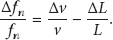
The calculation of

Conradi et al. used the transmission oscillator ultrasonic spectrometer (TOUS) [20] and later Jeyman alternatively used the reflection oscillator ultrasonic spectrometer (ROUS) [21] to measure changes in the resonant frequency of bolts due to stress-induced elongation and change in sound velocity. The experiments used the lead zirconate titanate (PZT) piezoelectric transducer to generate 5 MHz ultrasonic waves to measure the bolt stress. The experimental results confirmed linearity between the frequency shift and the applied stress.
Based on the pseudocontinuous wave technique, Joshi and Pathare [22] used the carrier phase detection technique to track the frequency shift of the mechanical resonance of the bolt. The experiment was carried out with frequency varying from 4891 KHz to 4953 KHz. The frequency changes linearly with the applied stress.
The time-of-flight change in the bolt is only about tens of nanoseconds, and the measurement result is susceptible to the environment interference especially in industrial sites. Additionally, most of the aforementioned methods require high sampling rate of several hundred kilo Hertz or even mega Hertz. The requirement of the high sampling rate and the associated high cost of the data acquisition systems are among the major obstacles to the practical adoption of in situ automated bolt structural health monitoring. In addition, the environmental noise as a main influencing factor for the precise measurement of the time-of-flight also hinders the application of the method in the field.
3. Piezoelectric Active Sensing Method
All surfaces, including those machined, are rough to different degrees, and, as a result, the contact between surfaces is restricted to discrete areas at the tips of the surface asperities. In this respect, all bolted joints also develop partial contact at their imperfect interfaces. The applied torque on the bolt may change the interfacial characteristics such as stiffness, damping, and true contact area. Once the interfacial characteristics changes are obtained, the tightness of the bolted connections can be determined.
Yang and Chang [23] provide an attenuation-based diagnostic method to identify the location of the loosened bolts, as well as to predict the torque levels of those bolts accordingly. The attenuation-based method is based on the damping phenomena of ultrasonic waves across the bolted joints. Incident waves are split into transmitted and lost waves at the micro contact interface. Considering the fact that waves are power transmission, the energy dissipation phenomena at the imperfect contact interface of bolted joints can be described by examining transmitted wave. Based on the fact that the wave propagation occurs mainly in the true contact area, the amount of transmitted wave energy is proportional to the true contact area. According to the classical Hertz contact theory, within the limit of maximum Hertzian pressure, the true contact area is proportional to the square root of the pressure applied to the contact surface. The torque level in a fastener affects the pressure of a contact surface at the bolted joint. Therefore, the torque level can be determined by measuring the transmitted wave energy.
Based on the above theory, Wang et al. [24] established the experiment apparatus with two PZT patches bonded to different sides of a bolted connection, as shown in Figure 2 [24]. In the active sensing method, one PZT is used to generate a stress wave that will propagate to across connecting surface, and the other PZT is used to detect the stress wave signal. The preloading force determines the connection condition and influences the wave propagation crossing the interface. By monitoring sensor signal, we can indirectly estimate the preloading force on the bolt.

Bolt connection status testing device.
As shown in Figure 2 [24], two steel rectangular/circular plates are connected by a pair of M10 bolt and nut, and the bolted connection is fastened by a torque wrench with different torque levels during the experiments. The computer generates a five-peak Gaussian pulse with a center frequency of 100 KHz every 1 s, and then the signal is converted into analog signals by the NI multifunction DAQ device NI USB-6361 to actuate PZT1. PZT1 produces an ultrasonic wave, which propagates from the top plate to the bottom plate through the bolted interface, and then the transmitted wave is captured by PZT2. The signal of PZT2 is converted to a digital signal by NI USB-6361 and saved in the computer for further analysis. The received signal energy of PZT2 is then calculated.
The experiment results are shown in Figure 3 [24]. It can be seen that, when the torque is under 40 N·m, with increase of the torque level, the received signal energy of the sensor (PZT2) also increases. However, when the applied torque is beyond 60 N·m, the received energy has little changes and it is in a saturation state. That is, because of exceeding this torque level, there is no more deformation space in the contact interface and the true contact area has basically no change thus; the received energy has little change.

Signal energy under different torque levels.
The experimental results demonstrate the feasibility of this method for bolt looseness monitoring. Since this method is easy to implement and nondestructive in nature, it is suitable for in situ bolt monitoring for practical use. The piezoelectric active sensing method has a tunable and high-frequency bandwidth. It is especially suitable for monitoring bolted joints, which involve interfaces. In the active sensing method, the frequency for data acquisition can be much lower than those used in the acoustoelastic effect based methods, thus lowering the hardware cost.
With a piezoelectric wafer as an actuator and a sensor, when the ultrasonic wave generated by the wafer is incident at the interface in the bolted joints, it is transmitted through the asperity junctions and reflected back at the air gaps. When the ultrasonic wavelength is long compared to the scale of the air gaps in the interface, the interface as a whole behaves like a reflector. Marshall et al. use the reflection coefficient of the ultrasonic for measuring the contact pressure relaxation in bolted joints [25].
PZT-induced Lamb wave-based methods are often used for bolt loosening detection. In general, this type of method is also active sensing based. Doyle et al. experimentally investigate the bolted space structures with the acoustoelastic damage detection method and the results show a good linear relationship between the Lamb wave signal delay time in the propagation path and the applied torque [26]. The support vector machine (SVM) was used for damage detection of bolted joints and the feature vectors were created by computing the Fourier amplitude at the excitation frequency using running Fourier transformation [27]. The wavelet transform and pattern recognition techniques, as probabilistic neural networks (PNNs) and support vector machines, are employed for the damage detection for a specimen made of two steel plates jointed by eight steel bolts, in which the damages were introduced by removing several bolts from the joints [28, 29]. The power spectral density (PSD) of the recorded signal was developed to assess the loosening state of joints by Amerini et al. [30]. In [31], the acoustic moment method, the second harmonic method, and the sidebands method were used to analyze the relationship between the tightening/loosening states indices and the torque applied.
For the piezoelectric active sensing method, since lower frequency of the ultrasonic can be used, the cost of test equipment can be dramatically reduced. The signal of active sensing method is relatively easy to analyze and has a better noise immunity; therefore, this method may be more suitable for the industrial application.
4. Piezoelectric Impedance Method
The theoretical development of the application of impedance measurements to structural health monitoring was first proposed by Liang et al. [32] in 1994. In this technique, a piezoceramic patch is surface-bonded to the monitored structure and excited by an alternating voltage sweep signal, typically in the kilohertz range, by an impedance analyzer. The vibrating patch transfers its vibrations to the host structure and simultaneously, the structure influences the electrical circuit comprising the bonded patch and the ac source. A plot of conductance (real part of admittance) as a function of frequency constitutes a unique vibration signature of the structure, reflecting structural characteristics such as inherent stiffness, damping, and mass distribution. In this manner, the same patch acts as an actuator as well as a sensor. By adjusting the sensing frequency range, the impedance method can cover different sensing areas. For a large structure, the bolted connection status affects only the local dynamic characteristics of the structure. The impedance method is appropriate to study the local dynamics of the bolt joint with appropriate sensing frequency.
Utilizing the electromechanical coupling properties of piezoelectric materials and with the impedance method, Park et al. [33, 34] performed the experiment on a civil pipeline structure connected by bolted joints. The experiment demonstrated the capability of the impedance method to track and monitor the integrity of the typical civil facility. In most impedance methods, a damage index is used to assess the degree of tightness of bolts and it is difficult to quantitatively assess the bolt connection status.
A spectral element method (SEM), based on a wave propagation approach, was used by Ritdumrongkul et al. [35] to model the structure impedance where the piezoelectric ceramic patch is bonded. Through the measurement of the electrical impedance of a PZT actuator-sensor patch bonded on a bolted structure, the change in structural properties due to damage simulated by loosening the bolts is detected. By comparing the simulated result of the proposed model with the experimental results, the loosening of bolts is quantitatively identified as the change in stiffness and damping at the bolted joint. This method solves the problem of the quantitative detection of bolted connection status, but the SEM is a little complicated and not universal.
Combining the impedance method with other ultrasonic methods is another effective bolted structure health monitoring technique. Wait et al. [36] combined the impedance method with the Lamb wave propagation based approach to analyze bolted system's structural integrity. An and Sohn [37] illustrated an integrated impedance and guided wave-based damage detection techniques by utilizing impedance and guided wave signals simultaneously obtained from surface-mounted piezoelectric transducers to the detection of bolt loosening. For the combined impedance method, it can detect the loosened bolt position in bolts group joints.
A precision impedance analyzer has a high cost. Wireless impedance devices based on AD5933 impedance measurement chip have been designed and used for structure health monitoring with reduced cost and size [38–41]. However, the limited scanning and sampling frequency of the impedance chip restricts its wide application [42].
For all above impedance methods, they determine the bolted connection status by impedance signal analysis. An effective monitoring theory is not formed yet because of lack of research for bolted structural dynamic characteristics, especially local high-frequency dynamics. The impedance method is very suitable for local dynamic characteristics study because of its high actuation frequency and tunable sensing area. Using the impedance method to investigate the dynamic characteristics of the bolted join may be the further research interests. Once understanding the effects of the bolt connection status on the local dynamic, the impedance method has a good potential for in situ monitoring of bolted connections.
5. Conclusion
Bolts are widely used to assemble components in mechanical and civil structures due to their high reliability, strong load bearing capacity, and easy maintenance. However, bolt connections are often subjected to external dynamic loads, such as impact, vibration, and thermal stresses, and bolt loosening leads to the failure of engineering structures. Therefore, the detection of bolt loosening, as a part of structure health monitoring, attracts much attention, and the development of a nondestructive testing method is needed to evaluate the state of bolt connection. This paper reviews three main methods for the bolted joints monitoring.
For the acoustoelastic effect based method, including time-of-flight method, velocity ratio method and mechanical resonance frequency shift method can determinate the bolt axial stress. It is an ideal way for the bolted structure monitoring, but the stress-induced velocity changes are quite small; thus the time-of-flight variation and frequency shift are very small, requiring a high sampling rate for the data acquisition device and thereby increasing the cost. There are many factors, such as the material-microstructure effects, environmental noise, and the thickness of bonding layer, which can affect the measurement accuracy of the flight time and make in situ measurement challenging.
Bolt preload changes the dynamic characteristics of the interface, such as stiffness and damping, and it affects the ultrasonic wave, which is generated by the piezoelectric transducer, passing through the interface. By monitoring and analyzing the received ultrasonic signal, the bolt connection status can be determined. Experimental results show that the piezoelectric sensing method based on interfacial characteristics change is an effective method. With further in-depth research in bolted contact interface properties, contact interface dynamic characteristics, and local dynamics, this method has a great potential for in situ bolt health monitoring.
The piezoelectric impedance method has a high sensitivity to the local structure damage and a large-frequency bandwidth. It is specially fitted for monitoring bolted joints which are dominated by local dynamics of high-frequency characteristics. The impedance method has a good potential for in situ monitoring of bolted connections.
The comparison of the methods discussed in this paper is listed in Table 1.
Comparison of the test method.

Though fiber optical sensors (FOSs), such as fiber bragg gratings (FBGs), have found many applications in structural health monitoring [43, 44] due to their advantages, including high accuracy, multiplexing capacity, and EMI (electromagnetic immunity), use of FOSs for bolted connection monitoring is rarely reported. The authors think that FOSs, especially FBGs, possess a great potential to monitor bolt looseness in real time, especially for applications involving high electromagnetic interference. The multiplexing capacity of FOSs is another attraction for bolted connection monitoring in case of a large number. With sensor optimization algorithms [45], a limited number of fiber cables can provide in situ monitoring of many bolted connections.
Footnotes
Acknowledgments
This research was partially supported by the Open Fund of the Key Laboratory for Metallurgical Equipment and Control of Ministry of Education in Wuhan University of Science and Technology, the Natural Science Foundation of Hubei Province under Grant no. 2011CDA121, and the Natural Science Foundation of China under Grant nos. 51375354 and 51105284.