
Abstract
433 MHz is getting more attention for Machine-to-Machine communication. This paper presents the DASH7 Alliance Protocol, an active RFID alliance standard for 433 MHz wireless sensor communication based on the ISO/IEC 18000-7. First, the major differences of 433 MHz communication compared to more frequently used frequencies, such as 2.4 GHz and 868/920 MHz are explained. Subsequently, the general concepts of DASH7 Alliance Protocol are described, such as the BLAST networking topology and the different OSI layer implementations, in a top-down method. Basic DASH7 features such as the advertising protocol, ad-hoc synchronization and query based addressing are used to explain the different layers. Finally, the paper introduces a software stack implementation named OSS-7, which is an open source implementation of the DASH7 alliance protocol used for testing, rapid prototyping, and demonstrations.
1. Introduction
Machine-to-Machine (M2M) communication can be organized using a wide area network (WAN), such as a mobile network, or a personal or local area network (PAN/LAN). Sensor communication is typically done using a PAN with a backbone connection using a wired or wireless WAN [1]. According to Beale and Morioka [1], the most frequently used technologies for wireless PAN are Wi-Fi (IEEE 802.11), Zigbee (which is based on IEEE 802.15.4), Z-Wave, and KNX-RF. The frequencies used by these technologies are 2.4 GHz, 868, and 915 MHz. Fadlullah et al. [2] also identify Bluetooth, Ultra Wide Band (UWB) and 6LoWPAN as prominent technologies suitable for M2M communication. Besides the aforementioned frequencies, 433 MHz is also gaining relevance in the area of M2M communication, as stated by Tuset-Peiro et al. [3].
Niyato et al. [4] also identify an neighborhood area network (NAN) which typically connects different homes using a so called concentrator to a base station of the WAN. They focus on home energy management. Such application consolidate the search for other low-power RF technologies which have a longer range than typical PAN technologies. This paper will introduce such a technology: the Dash7 Alliance protocol.
The DASH7 Alliance protocol (D7A) [5] is an active RFID alliance standard for 433 MHz wireless sensor communication based on the ISO/IEC 18000-7 standard maintained by the DASH7 Alliance. ISO/IEC 18000-7 defines parameters of the active air interface communication at 433 Mhz. D7A is built on top of an asynchronous Wireless Sensor Network (WSN) Media Access Control (MAC). In contrast to typical WSN standards such as ZigBee (built on top of IEEE 802.15.4), the DASH7 specification defines a full functional RFID tag. This means it does include high level functionality optimized for RFID applications. However, it can also be extended for non-RFID applications. In contradiction to legacy RFID systems [6], D7A supports tag-to-tag communication.
DASH7 uses a BLAST network technology. BLAST is an acronym for Bursty, Light, Asynchronous, Stealth, Transitive. Bursty means abrupt data transfer unlike streaming content such as video or audio. Light refers to a limited packet size (256 bytes). Multiple consecutive packets are however supported. Asynchronous is one of the key concepts of DASH7. Communication is command-response based without any periodic synchronization. Stealth refers to the fact that DASH7 does not need any periodic address broadcasting, which means nodes can choose to communicate only in trusted environments. Transitive refers to the mobile transitional behavior of devices and/or tags.
This paper will first explain the major differences of 433 MHz communication compared to more frequently used frequencies in Section 2. Subsequently, it will describe the general concepts of the D7A specification in Section 3. Finally, it will introduce a software stack implementation OSS-7 in Section 4.
2. 433 MHz Based Sensor Communication
As stated before, 433 MHz is not the most widely used frequency for M2M communication, although it has some serious advantages. First of all, it is an unlicensed band which is almost worldwide applicable; however, it is not harmonized. The band spans from 433.05 to 434.79 MHz. Second, due to its frequency, it has better propagation characteristics opposed to higher frequencies. This is discussed later in this section. However, there are also some disadvantages. The wavelength at the center frequency 433.92 MHz is 69.14 cm. This means an
Some research has already been done in comparing the propagation aspects of 433 MHz towards other frequencies.
Tuset-Peiro et al. [3] compare the propagation performance of 433 MHz and 2.4 GHz and show that 433 MHz has a better communication range despite the effects of having a larger Fresnel zone. They also show that channel hopping will not solve multipath propagation effects since the channel coherence bandwidth is larger than the whole 433 MHz band.
Isnin [7] compares path propagation in multifloored building for 433, 868 and 1249 MHz. The 868 MHz band has a higher bandwidth then the 433 MHz band which enables a higher data rate. They show that in a waveguided corridor environment with line-of-sight, higher frequencies have an advantage. However, 433 MHz has a better penetration capability. This leads to a lower path loss-level for multi-floor propagation with the number of floor obstruction greater then two. Zhang et al. [8] state that it is very complex to model small scale indoor propagation.
As already stated, the regulations of 433 MHz transmissions are not harmonized.
In Europe, ETSI states for short-range devices (SRD) that the band from 433.05 till 434.790 MHz can be used for nonspecific SRD with 10 mW Effective Radiated Power (ERP) when the duty cycle is less than 10% or when then channel spacing is smaller than 25 kHz or with 1 mW ERP without duty cycle limitations [9].
In USA, FCC states that the field strength can only be 10995 μV/m at 3 meter for periodic applications and 4398 μV/m at 3 meter otherwise [10, 11]. This corresponds with an ERP of −14.4 dBm for periodic control applications and −22.36 dBm otherwise.
3. DASH7 Alliance Protocol
This section will describe the basic concepts of the DASH7 Alliance protocol (D7A).
D7A defines four different device classes as shown in Table 1. A device can switch between classes. A blinker device only transmits data and does not use a receiver. For this, a blinker, for example, cannot perform carrier sensing. A second class is an endpoint. This is a typical low power device which can transmit and receive data. An endpoint also supports wake-up events. This enables the device to receive requests and typically transmit a response. A gateway device is in most cases the device which connects the D7A network to another network. A gateway is obliged to support all D7A features and is never offline. It always listens unless it is transmitting. A subcontroller is a full featured device as well, but it is not always active. It uses wake on scan cycles, just like the endpoint devices. This will activate the device for short channel scanning.
D7A devices classes.

D7A describes a full functional RFID tag. Every device supports one or more of the aforementioned+ device classes. For this a correctly configured tag is fully functional without the need for specific application code. Although, in most cases specific application code will be added.
DASH7 supports two communication models: pull and push. As in most RFID systems, dialogs between tags and interrogators are query response based (the pull model), as shown in Figure 1(a). This request response mechanism is described by the D7A Query Protocol (D7AQP). Data transfer initiated from the tags to the gateway on the other hand is based on the push model. This is shown in Figure 1(b). This approach can, for instance, be implemented as an automated message or beacon which is sent on specific time intervals. In D7A, this system is called Beacon Transmit Series.

Communication models.
DASH7 defines two types of frames: a foreground frame and a background frame. The foreground frames are regular messages which contain data or data requests. Background frames on the other hand are very short broadcast messages. Background frames are for instance used by the D7A Advertising Protocol (D7AAdvP) for rapid ad-hoc group synchronization. This D7AAdvP enables a low power wake-up of those tags which are interrogated in the pull model.
The D7A specification involves all 7 OSI layers [12] and describes the protocol in each of those layers. However, some of the features are still under revision or reserved for future extensions. Figure 2 gives an overview. The remainder of this section describes the D7A implementation of the application layer and how its features are supported by the underlying layers.
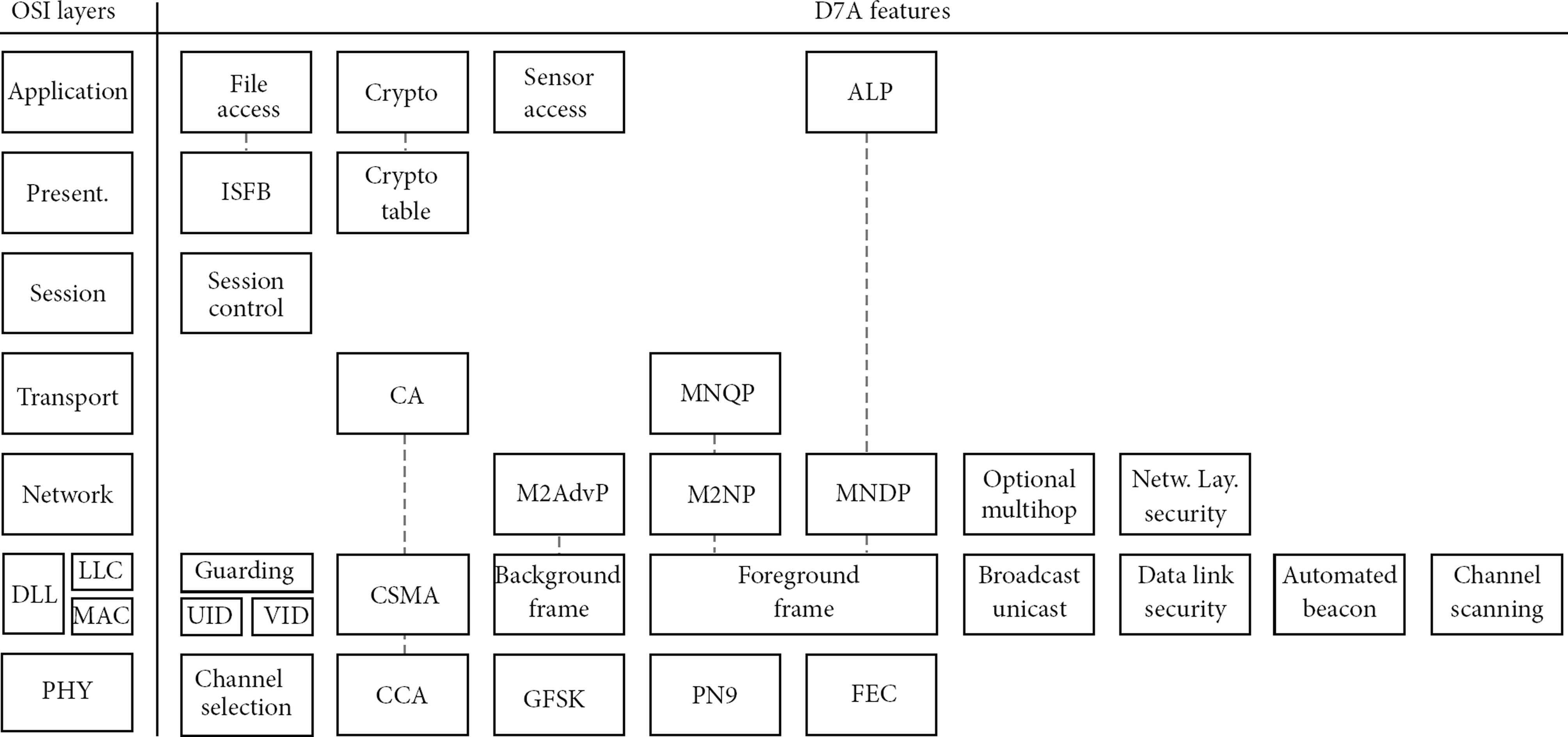
OSI layers with DASH7 specification.
The D7A Query Protocol, the Advertising Protocol and the beaconing concept will be used as an example to clarify the different layers.
3.1. D7A Application Layer
The application layer typically describes the interaction between the application software and the communication stack. The application layer enables the software application, which is used by the user, to be able to access communication resources, identify communication partners, and activate certain communication concepts.
In D7A, this layer describes the so called Application Layer Protocol (ALP), the file access protocol, the cryptographic authentication protocol, and access to the sensor subprotocol. The ALP makes it possible to send specific data, structured by the application. This is in contrast to D7A specific data protocols which are described in other layers. The cryptographic authentication description is at the time of writing still under revision, but the underlying layers already support the necessary data fields. The sensor subprotocol is based on ISO 24151-7 [13] and specifies the representation of specific sensor data. The file system protocol describes the access methods (read, write, and execute) to the file system which is described in the presentation layer.
Accessing a file is based on the File Data Access Template, shown in Table 2. The File ID refers to a specific file (see Section 3.2: presentation layer). The other two values define the location in the file to be read from or written to. The data field is the actual data to be written.
File data access template.

A beacon transmit series uses an automated process in the Data Link Layer. This process is enabled, disabled and configured by a configuration file described in the presentation layer.
3.2. D7A Presentation Layer
Every D7A device needs to support a number of data elements. D7A has three types of data elements: Indexed Short File Series Blocks (ISFSB), Indexed Short File Blocks (ISFB), and Generic file Blocks (GFB). All of these blocks have their own permission code. This code defines the read, write an execute rights of the root user, current user and guests. An ISFSB is a collection of ISFB files. ISFB Files are stored as structured, mixed-data strings. ISFB IDs specify different files. For example, 0x00 specifies the network configuration, 0x01 specifies device capabilities and supported features, and 0x06 specifies a time controlled sequence for beaconing,…. The beaconing will be further explained in Section 3.6.
The data defined by the presentation layer for beaconing is shown in Table 3. The Channel ID is the physical layer Channel ID, defined in Section 3.7. The Command Parameters are bitfield parameters that map to data link layer and D7AQP parameters. The D7AQP Call Template defines the file or file series template which will be used as data. The Next Beacon is the number of ticks between the beacons. A tick is
Beacon transmit period list.

The network configuration settings (ISFB file with ID 0x00), determines the active device class (gateway, subcontroller, endpoint or blinker). It will also define if the device is capable of using Forward Error Correction (FEC), hi-rate channels, and other features which are used by the data link and physical layer.
3.3. D7A Session Layer
The session layer specifies which events may trigger session initiation or scheduling. It describes management and prioritization of multiple scheduled sessions and idle state of the data link layer. Moreover it supports a power level auto-scaling framework to optimize battery usage. This technique will adapt the transmission power to find an optimum between power consumption and a stable wireless connection.
In a standard situation the subcontrollers and endpoints operate after a wake-on event. The wake-on events defined by D7A are automated channel scanning, automated beacon transmit series (both described in the data link layer), and any application layer relevant events (e.g., sensor event or a passive scanning).
The session layer creates a random session number for any new initiated session. This random number is used in the D7AQP as a dialog ID. The session layer also keeps track of a device's network state. The possible states are associated, scheduled, promiscuous, and unassociated.
A host supporting the D7A Advertising protocol in the network layer also has to implement a session stack to enable session scheduling. This session stack keeps track of the different initiated sessions. Ad-hoc sessions have a higher priority than scheduled sessions (such as beaconing) and are always added on the top of the stack.
3.4. D7A Transport Layer
Generally, the transport layer provides end-to-end communication services. In D7A, this is covered by the D7A Query Protocol Transport Layer (D7AQP). It is responsible for communication structuring, flow- and congestion control, and addressing beyond the subnet filtering. In this section, first the communication dialogs of D7AQP will be described. Afterwards the command structuring and finally collision avoidance.
3.4.1. D7AQP Dialogs
The transport layer supports two types of dialogs: Nonarbitrated Two-Party Dialog (NA2P) and Arbitrated Two-Party Dialog (A2P). The NA2P is a one-time dialog between a requester and a responder or responders. The requester is a single host which sends a single request. The responders can be any host addressed in the request. Besides the query itself, the requester sends an addressing method, a list of channel IDs which can be used for the responses and two time parameters (

Nonarbitrated Two-Party Dialog Example.
In contrast to a NA2P dialog, the A2P dialog is a persistent dialog between requester and responders. A2P enables the global and local addressing, which is an important feature of D7A. An example is shown in Figure 4. The first request includes global and local addressing. The global addressing notifies a large group of potential responders to stay alert for a query. The local addressing queries a subgroup of these potential responders. All responders have to respond within

Arbitrated Two-Party Dialog Example.
3.4.2. Command Structuring
The transport layer also defines the structure of the command-response protocol (the command structure). The command structure is based on templates. It contains the addressing method, the command code and command extension.
In a request, the addressing method can be broadcast, unicast, multicast or anycast. In case of broadcast and unicast, the command contains a command extension and command data. In case of anycast, the command also includes a global query. A global query is a query using global addressing, as described in the previous subsection. In case of multicast, the command contains a global query and local query or a local query with an acknowledgment template. A response is always unicast and can contain command data or an error.
The command code contains a command type. It defines if the command is a response, an error response, a Nonarbitrated Two-Party Dialog, or an Arbitrated Two-Party Dialog. In the latter case, it defines whether it is an initial request, a intermediate request or a final request. These dialogs are explained in the previous subsection.
The command code also contains an opcode. It specifies if the command wants to announce a file or do an inventory or collection. An inventory means it will request a list of files. A collection means it will request the content of some file. The command can also define a so called application shell which means it encapsulates an application's specific data.
And finally, the command extension defines if CSMA is used for responses and which type of collision avoidance is used. This is explained in the next subsection.
3.4.3. Collision Avoidance
A third important component of the transport layer is collision avoidance (CA). In case a message is sent from the transport or higher layer, the transport layer is responsible for collision avoidance and flow control. The data link layer is responsible for the CSMA process as is explained in Section 3.6. The CSMA-CA process uses the 
This is the time within a packet has to be transmitted to make sure it has been sent before
Three CSMA-CA and flow control models are defined by D7A: Adaptive Increase No Division (AIND); Random Adaptive Increase No Division (RAIND); Random Increase Geometric Division (RIGD).
AIND and RAIND use a fixed slot length which is approximate the duration of the transmission. In AIND, the CSMA process starts in the beginning of a slot. In RAIND, the CSMA process only starts after a random delay which is smaller than
3.5. D7A Network Layer
The network layer defines the Background Network Protocol which is used for the D7A Advertising Protocol (D7AAdvP) and the Foreground Network Protocol which is used for queries, responses and beacons.
3.5.1. Background Network Protocols
Background network protocols contain very short background frames (BF). Background frames are described in Section 3.6. Currently, only the D7A Advertising Protocol is defined as a background network protocol. D7AAdvP is used exclusively for rapid, ad-hoc group synchronization. It is a transmission only, broadcast protocol. D7AAdvP is used to notify hosts about a request which will be send in the future. The requester floods the channel with background frames which contains a time span until when the request will be sent. The responder hosts receive the background frame while listening for a background frame during background scanning (as described in Section 3.6), and can go to a sleep state until the request is planned to be received. The responder only has to receive one background frame to know this timing. This leads to a very low power consumption optimized method of ad-hoc synchronization. Figure 5 shows an example of such a synchronization train.

Example of the use of the D7A Advertising Protocol.
3.5.2. Foreground Network Protocols
Two foreground network protocols are defined by D7A: the D7A Network Protocol (D7ANP) and the D7A Datastream Protocol (D7ADP). The D7ANP is an addressable, routable protocol which is used for the D7A Query Protocol in the transport layer. The D7ADP is a generic data encapsulation protocol, which contains no routing or addressing information. It allows for maximum flexibility towards the upper layers. The D7ADP is, for example, used by the Application Layer Protocol.
The D7ANP supports network layer security and standard two hop routing. It implements unicast, broadcast, multicast and anycast addressing to support the D7AQP Dialogs.
3.6. D7A Data Link Layer
The data link layer (DLL) of D7A, specifies the data link filtering, addressing, the dialog models, MAC processing, frame construction and the field definitions.
3.6.1. Data Link Filtering
Incoming frames are filtered by three processes. The first one is a Cyclic Redundancy Check (CRC) validation with a 16 bit CRC16 field. The calculation uses the CCITT CRC16 polynomial. If the CRC16 validations passes, subnet matching or link quality assessment can be performed in an arbitrary order. The subnet is constructed with a 4 bit specifier and a 4 bit mask. If link quality assessments is enabled, the link budget should be higher than a predefined link quality threshold. This makes further frame processing possible.
3.6.2. Data Link Addressing
Related to addressing, the data link layer of the D7A protocol specifies an ISO 15963 [14] compliant Device ID manifesting in a fixed Unique ID (UID) and a dynamic network-unique Virtual ID (VID).
The UID is a EUI-64 (Extended Unique Identifier) compliant ID [15]. It contains a 24 or 36 bits Organizationally Unique Identifier (OUI) assigned by the IEEE Registration Authority based on a 40 or 28 bits serial number. The VID is a 16 bit ID which is supplied by the network administrator and should be unique within the network.
The data link layer only supports unicasting and broadcasting. If a target Device ID is present in the frame, it will be processed as a unicast message. The Device ID of the frame will be matched with the destination devices ID. The frame will only be processed by the upper layers when a match exists.
3.6.3. Frame Structure
As already mentioned in the network layer, the data link layer has background frames and foreground frames. A background frame is a fixed length 6 byte frame, proceeded by a sync word of class 0 (defined in Section 3.7). The structure of a background frame is shown in Table 4.
Background frame structure.

A foreground frame has a variable length, up to 255 bytes, proceeded by a sync word of class 1. The structure is shown in Table 5. The length byte is the total number of bytes, including the length byte and the 2 byte CRC.
Foreground frame structure.
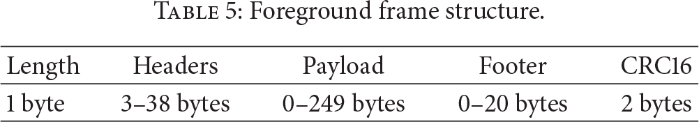
The headers contain information related to optional data link layer security, address control (source and optional destination id), the subnet, and the estimated radiated power of the transmission (TX EIRP). This value can be used by the receiving node to estimate the link budget.
3.6.4. Data Link Dialog Models
Following the same concept of foreground and background frames, two related dialog models are defined.
A Background Dialog (not really a dialog) starts when a background frame starts transmitting and ends as soon as it finishes transmitting.
A Foreground Dialog is a dialog between devices and is used to support the D7A Foreground Network Protocols. An overview is shown in Figure 6. The response contention period
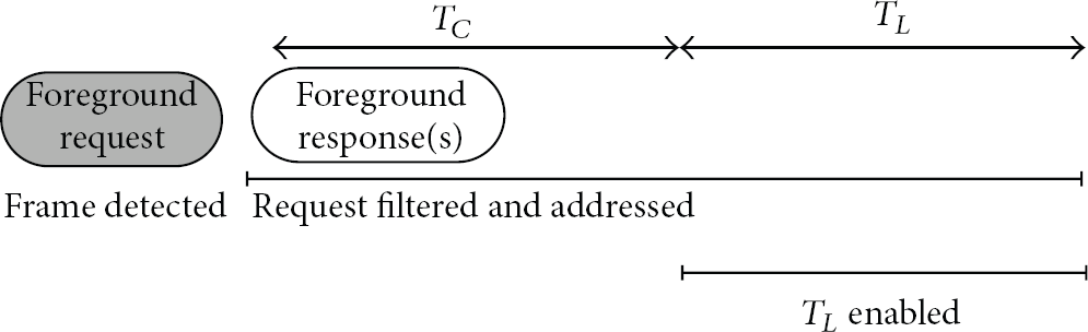
Overview of the foreground frame dialog model.
3.6.5. MAC Processing
The data link layer supports an automated scanning method. Using this scan scheduler the data link layer can scan for background or foreground frames.
In a background scan, the D7A device first checks the energy level. Only if the level is sufficient does it try to detect the correct sync word (class 0 for background scanning). In foreground scanning the device first searches for a sync word of class 1.
Using the automated Channel Scan Series, the data link layer can follow a predefined sequence of background or foreground scans. The series is defined by a list of channel IDs (explained in Section 3.7), scan types (background or foreground), a “Scan Detection Timeout”
The Beacon Transmit Series is another automated data link layer process. This process sends predefined beacons at specified time intervals and channel IDs.
The data link layer is also responsible for MAC channel guarding. A Nonguarded Channel (NGC) is a channel which does not require CSMA. A Guarded Channel (GC), however is a channel which does require CSMA. CSMA is also implemented by the data link layer. In this case CSMA-CA ensures that a transmission is only executed when a channel is unguarded. After a transmission a guarding period
3.7. D7A Physical Layer
The physical layer defines the spectrum utilization and channels, the modulation, the symbol encoding, and the packet structure.
3.7.1. D7A Spectrum
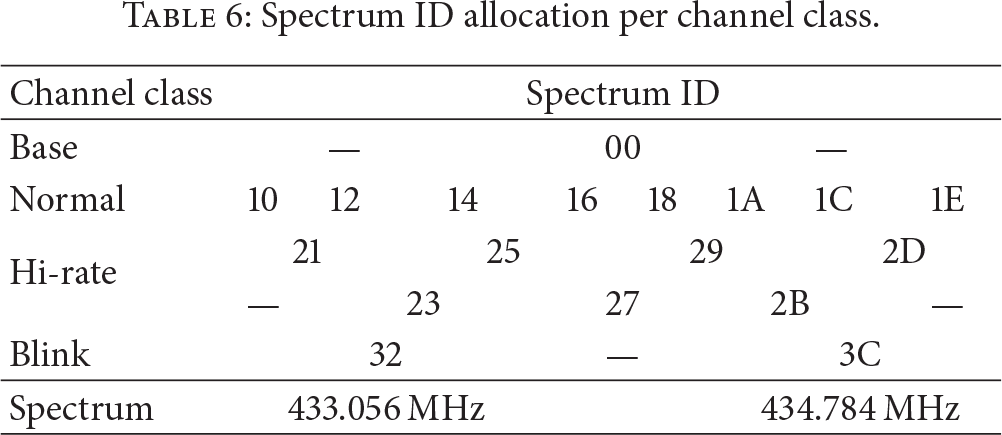
The spectrum allocation and channels are shown in Table 6. The spectrum ID specifies which channels and channel classes are used. The Channel ID is the Spectrum ID which is logically OR'ed with the encoding option. The value is 0x80 in the case Forward Error Correction (FEC) is used, otherwise the value is 0x00. The base and normal class have a bit rate of 55.555 kbs. The hi-rate and blink class have a bit rate of 200 kbs. The normal class has a channel bandwidth of 216 kHz. The hi-rate and base class have a channel bandwidth of 432 kHz. The blink class has a channel bandwidth of 648 kHz. Gaussian frequency shift keying is used as modulation technique.
Spectrum ID allocation per channel class.
3.7.2. Symbol Encoding
As a last stage before transmission, a data whitening [16] technique based on a 9-bit psuedo-random generator (PN9 encoding [17]) is used to avoid a DC offset in the transmitted data. For this, a PN9 decoding stage will be the first decoding step at the receiver.
Before the data whitening step, an optional forward error correction (FEC) can be executed [18]. For FEC, D7 uses convolution encoding with constraint length 4, followed by a 32 bit interleaving executed on 2 bit symbols. The interleave/deinterleave process lowers the impact of bursty errors since it separates adjacent symbols.
3.7.3. Packet Structure
On the physical layer, the frame structure of the data link layer is preceded by a preamble and a sync word. A preamble of typically 32 bits on the base and normal channels and 48 bits on the hi-rate and blink channels of alternating 0 and 1's is used to enable the receiver to calibrate the data rate circuit. The preamble is followed by a sync word. The sync word can be of class 0 or class 1 and depends on the use of FEC. After the sync word, comes the packet payload, which is defined by the upper layers. In all cases D7A uses the big endian format (most significant byte first).
4. OSS-7
OSS-7 [19] is an ongoing software stack implementation of the DASH7 Alliance Protocol mainly developed by the CoSys-Lab of the University of Antwerp. OSS-7 is being developed with its main goal to provide a reference implementation of the D7A specification. This means that code clarity and structure is more important than performance.
OSS-7 is implemented in ANSI C to be as compatible as possible with Texas Instruments (TI) Code Composer Studio (CCS), gcc and mspgcc.
The OSI layers, as shown in Figure 2, are used as structure for the implementation. All the layers are implemented as pluggable layers, which makes it easier to benchmark other implementations of a specific layer (e.g., a new proposal for a MAC implementation).
Besides the OSI layers, there are two additional layers: Hardware Abstraction Layer (HAL) and the “Framework” layer. Both layers implement an API which can be called from any other layer. The HAL makes an abstraction of hardware aspects such as I/O, buttons, LEDs, CRC software or hardware implementations, UART, timers, and the Real Time Clock (RTC). Currently a HAL implementation is provided for TI MSP430, TI Stellaris (ARM Cortex-M4) and posix hardware. Support for ARM Cortex-M3 is planned for the near future. The framework API provides hardware independent functionality like logging and queueing which is used within the stack but can also be used by the application.
The PHY layer consists mostly of an abstract interface. This Radio Abstraction Layer (RAL) is required to be implemented by radio chip specific code. This plugin system effectively allows us to support multiple radio chips. One can switch between them at compile time. Currently TI's CC430 (which is system-on-chip composed of a TI MSP430 and an TI CC1101 sub 1 Ghz transceiver) and an external CC1101 (with communication through SPI) are supported. Support for STMicroelectronics SPIRIT1 RF chip will be implemented in the near future.
Figure 7 gives an overview of the file structure of OSS-7. The different OSI layers are visible. RAL and HAL can be extended to different hardware.

File structure of OSS-7.
Besides the software stack itself, the OSS-7 project will also provide additional PC-based tooling for diagnostics, testing, and configuring tags running the stack.
4.1. Implementation
Figure 8 shows the devices which are used to implement and test OSS-7. Device (1) is a CoSys-Lab designed
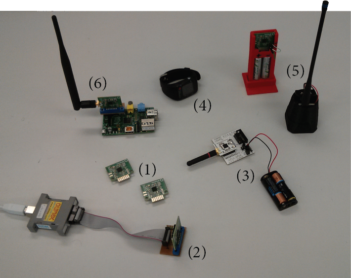
Devices used to implement OSS-7.
As an example, devices (1) and (5) are used by Stevens et al. [20] to test robot localization using DASH7.
5. Summary
This paper gave an high-level overview of the DASH7 Alliance Specification and introduced OSS-7, a stack implementation for this specification. D7A is built for low-power sensor communication with integrated concepts such as global and local querying, automated beacon transmits series and automated channel scanning. D7A describes a full functional RFID device.
OSS-7 is embedded stack implementation for D7A which currently supports CC430, CC1011, and ARM Cortex-M4. It is build using a modular structure following the D7A's ISO layering and a separate hardware and radio abstraction layer. OSS-7 focuses on transparency and code clarity to be used as a tool to explain the specifications and test new protocol adaptations.
Footnotes
Conflict of Interests
The authors declare that there is no conflict of interests regarding the publication of this paper.