
Abstract
We analyze and compare three different computational methods for a solar heating system with seasonal water tank heat storage (SHS-SWTHS). These methods are accurate numerical method, temperature stratification method, and uniform temperature method. The accurate numerical method can accurately predict the performance of the system, but it takes about 4 to 5 weeks, which is too long and hard for the performance analysis of this system. The temperature stratification method obtains relatively accurate computation results and takes a relatively short computation time, which is about 2 to 3 hours. Therefore, this method is most suitable for the performance analysis of this system. The deviation of the computational results of the uniform temperature method is great, and the time consumed is similar to that of the temperature stratification method. Therefore, this method is not recommended herein. Based on the above analyses, the temperature stratification method is applied to analyze the influence of the embedded depth of water tank, the thickness of thermal insulation material, and the collection area on the performance of this system. The results will provide a design basis for the related demonstration projects.
1. Introduction
The solar heating systems include the central solar heating plants with diurnal storage (CSHPDS) and the central solar heating plants with seasonal storage (CSHPSS). CSHPSS can transfer the solar energy from summer to winter. Its heat storage capacity is far beyond that of CSHPDS. Therefore, CSHPSS has become one of the most popular and potential systems for large-scale application of solar energy.
CSHPSS mainly consists of three parts, which are seasonal heat storage system, collection system, and heating system. According to different heat storage mediums, the seasonal heat storage systems are divided into two types, which are the sensible heat storage systems [1] and the latent heat storage systems [2]. The sensible heat storage systems include the embedded pipe heat storage system [3], the aquifer heat storage system [4], the gravel-water heat storage system [5], and the water tank heat storage system [6, 7]. For the embedded pipe heat storage system, the heat is stored in the surrounding soil by means of the embedded pipes underground. For the aquifer heat storage system, the heat is stored in the underground water by means of the cold and hot wells. However, due to the geological limitations, the applications of these two systems are restricted. The gravel-water heat storage system exchanges heat by the pipes installed in different layers inside the store. However, it is not widely applied due to its low heat capacity and great volume. The water tank heat storage system has relatively great heat capacity and good heat storage/releasing performance and is relatively less affected by geological structures. Therefore, it is most widely applied in the world. For example, among the ten largest solar energy heating demonstration projects in Europe, eight projects have adopted the water tank heat storage systems [1].
Presently, the calculation studies on the water tank heat storage system are mostly based on simplified models. Yumrutas and Unsal [8, 9] have made computational researches on the hemispherical water tank in earth. Flows and thermal stratifications in the water tank are omitted and the temperature is assumed to be uniform in the water tank. Then, an analytical solution is obtained for the transient temperature field outside the hemispherical water tank by the application of the Complex Finite Fourier Transform (CFFT) and the Finite Bessel Transform (FBT) techniques. Ucar and Inalli [10] have made computational researches on the trapezoid water tank embedded in earth. Same as the hemispherical water tank, the temperature is assumed to be uniform. Then, a finite element method is applied to compute the temperature field in the surrounding soil. Chung et al. [11] have applied TRNSYS software to research the columnar water tank on the ground surface, with the same assumption that the temperature in the tank is uniform. Empirical formulas are used to compute the thermal loss of the water tank. Nordell and Hellstrom [12] have established a soil heat storage model (DST) by TRNSYS and MINSUN with the same uniform temperature assumption, and empirical formulas are also used to compute and analyze the system. Presently, most of the computational researches are based on the uniform temperature assumption. However, the assumption is greatly different from the actual conditions; that is, there exist obvious thermal stratifications in the water tank. To work out an optimal solution, this paper compares the three different computational methods (accurate numerical method, temperature stratification method, and uniform temperature method) for the solar heating system with seasonal water tank heat storage (SHS-SWTHS).
2. Basic Structure of SHS-SWTHS
This paper makes researches on the SHS-SWTHS for a 9,000 m2 building located at Beijing, China. The system consists of three parts, which are collection system, heat storage system, and heating system, as shown in Figure 1.
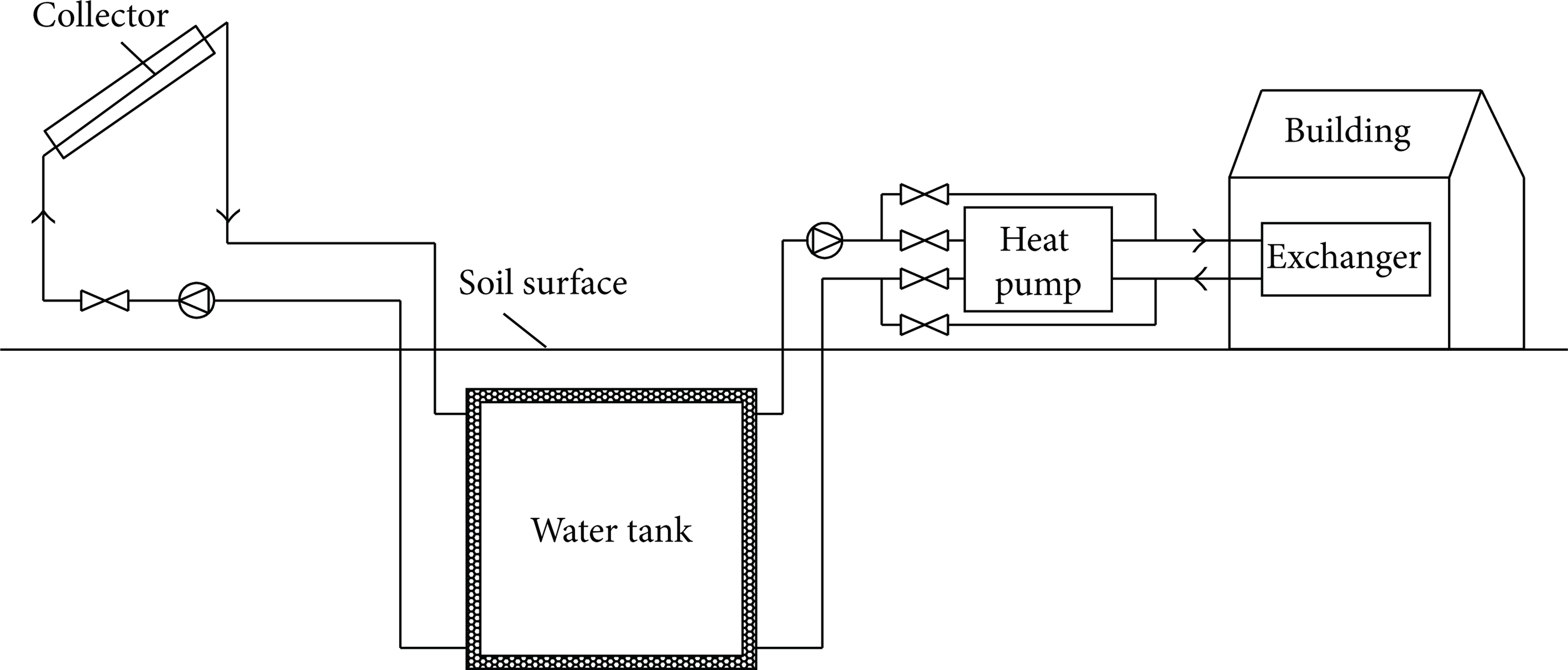
Solar heating system with seasonal water tank heat storage (SHS-SWTHS).
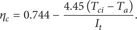
The solar collector is flat type and installed horizontally. The collection efficiency η c is influenced by the inlet temperature T ci , the ambient air temperature T a , and the solar radiation intensity I t . According to the efficiency curve provided by the manufacturer, its efficiency [2] is expressed as follows:
The collected energy is

where A
c
refers to the collection area. The unit area flow rate of the solar collector is set as 0.01 kg·m−2·s−1. Therefore, the flow rate of the collection system when opened is 0.01A
c
, that is,
The water tank is a cube with the side length of L = 15 m and the volume of V t = 3375 m3. It is embedded underground.
The thermal load of the building during the heating period is

where (UA) h refers to the thermal load of the building under unit temperature difference and equals to 16665 W·K−1. T i refers to the indoor design temperature and equals to 18°C. To meet the requirement of thermal load, the fluid temperature in the heat exchangers should match the following condition:
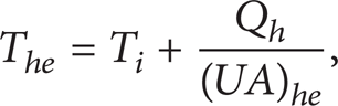
where (UA)
he
refers to the heat transfer rate of the heat exchangers under unit temperature difference and equals to 13887.5 W·K−1. The flow rate of the heating system when opened is 9 kg·s−1, that is,

When T hi ≤ 288 K, the heating system is closed.
3. Introduction of Three Different Computational Methods
Introductions will be made, respectively, on the accurate numerical method, the temperature stratification method, and the uniform temperature method as follows.
3.1. Accurate Numerical Method
In the accurate numerical method, the governing equations are given based on the fluid flow and heat transfer in the water tank and the coupled heat transfer between the water tank and the surrounding soil, and the collection system and the heating system are given as boundary conditions. Due to the symmetry of the structure, this paper applies one-quarter of the water tank and the surrounding soil as computational domain, as shown in Figure 2. The distance from the water tank bottom to the boundary A′B′C′D′ is 10 m, and the distances from the water tank sides to the boundaries AA′B′B and BB′C′C are, respectively, 15 m.

Computational domain of the SHS-SWTHS used for the accurate numerical method.
The governing equations are given based on the assumptions which are laminar, incompressible, and constant properties.
Continuity equation:

Momentum equation:

Energy equation:
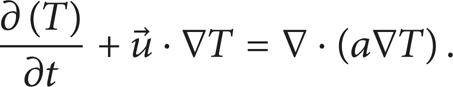
Here, the Boussinesq assumption [13] is adopted to deal with the buoyancy force term in the momentum equation.
Solar radiation intensity, outdoor temperature, and outdoor wind speed are obtained from the meteorological data of Beijing. The heating period of Beijing is from November 15 to March 15. This paper selects the time 00:00 on March 16 as the starting time of the computation. The initial temperature in the surrounding soil is calculated according to the following formula [14]:

The initial temperature and the initial velocity in the water tank are set as 288 K and 0 m/s, respectively.
The velocity boundary condition at the water inlet of the collection system is
The temperature boundary condition is

The velocity boundary condition at the water outlet of the collection system is

The temperature boundary condition is
The velocity boundary condition at the water inlet of the heating system is
The temperature boundary condition is

The velocity boundary condition at the water outlet of the heating system is

The temperature boundary condition is:

The temperature boundary condition at the soil surface ABCD [10] is

The temperature at the soil bottom A′B′C′D′ is 288 K. The temperature boundary conditions at AA′D′D, DD′C′C, AA′B′B, and BB′C′C are symmetrical boundary conditions.
This paper uses the implicit and unsteady solver with double precision for the solution of the system of governing equations [15]. The momentum and energy equations are discretized using the second-order upwind scheme, pressure equation by body force weighted scheme. The discretized equations are solved using the PISO algorithm. The time step is set as 900 s.
3.2. Temperature Stratification Method
The temperature stratification method is established based on the multinode model. The water tank is stratified uniformly into N layers. The water temperature in the same layer is uniform, while the temperatures in different layers are different. Then the computations are made based on this assumption. Figure 3 shows the computational domain of the SHS-SWTHS. For convenience, only central sectional view is given herein. The computational process consists of two steps. Step 1: calculate the temperatures in different layers of the water tank; Step 2: calculate the temperature distribution in the surrounding soil. The computational process is detailed as follows.

Computational domain of the SHS-SWTHS used for the temperature stratification method.
Step 1. Calculate the temperatures in different layers of the water tank.
The flow rate of the collection system is

The flow rate of the heating system is
The total flow rate of the collection and heating systems is given as
The energy conservation expression in layer 1 of the water tank is given as follows:
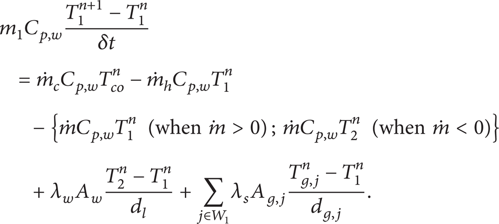
The term of the left side of (21) represents the heat change in layer 1 during the time interval δt. The first term of the right side represents the heat inflow from the collection system to layer 1. The second term of the right side represents the heat outflow from layer 1 to the heating system. The third term of the right side represents the heat outflow from layer 1 to layer 2 if
The energy conservation expression in the intermediate layer I (1 < I < N) of the water tank is described as follows:

The energy conservation expression in the last layer N of the water tank is described as follows:

The initial temperature in the water tank is set as 288 K.
Step 2. Calculate the temperature distribution in the surrounding soil.
The temperature distribution in the surrounding soil can be obtained by solving the following energy equation:

The initial temperature in the surrounding soil is computed according to (9). The temperature boundary condition at the soil surface AC is described as (18). The temperature at the wall surface of the water tank is T I , which may be calculated according to Step 1. The temperature at the soil bottom BD is 288 K. The temperature boundary conditions at AB and CD are symmetric boundary conditions.
3.3. Uniform Temperature Method
The uniform temperature method is a special case of the temperature stratification method. When the layer number N = 1, the temperature stratification method can be seen as the uniform temperature method.
4. Comparison and Analysis of Three Different Computational Methods
This paper compares and analyzes the accurate numerical method, the temperature stratification method (N = 10), and the uniform temperature method. Here, the soil type is sand and its thermal properties are detailed in Table 1. The collection area is 1200 m2; the embedded depth of water tank is 2 m; and the thickness of thermal insulation material is zero.
Thermal properties of two typical soils.

The accurate numerical method can accurately predict the performance of the SHS-SWTHS, but it takes about 4 to 5 weeks, which is too long and hard for the performance analysis of this system.
As shown in Figure 4, the average water tank temperature computed by the temperature stratification method is basically consistent with that of the accurate numerical method. As shown in Table 2, the error of the yearly heat loss of the water tank is 5.1% compared with the accurate numerical method. The error of the yearly collection efficiency is 0.3%. The error of the yearly solar fraction is 0.3%. Here, the solar fraction equals to the ratio of the heat provided by the system over the thermal load of the building. The computation results agree very well with the accurate numerical method. Therefore, the accuracy of the computation results by the thermal stratification method is high. Meanwhile, the computation time is short, which is about 2 to 3 hours. Therefore, this method is optimal for the performance analysis of this system.
Yearly computation results calculated by three different methods.

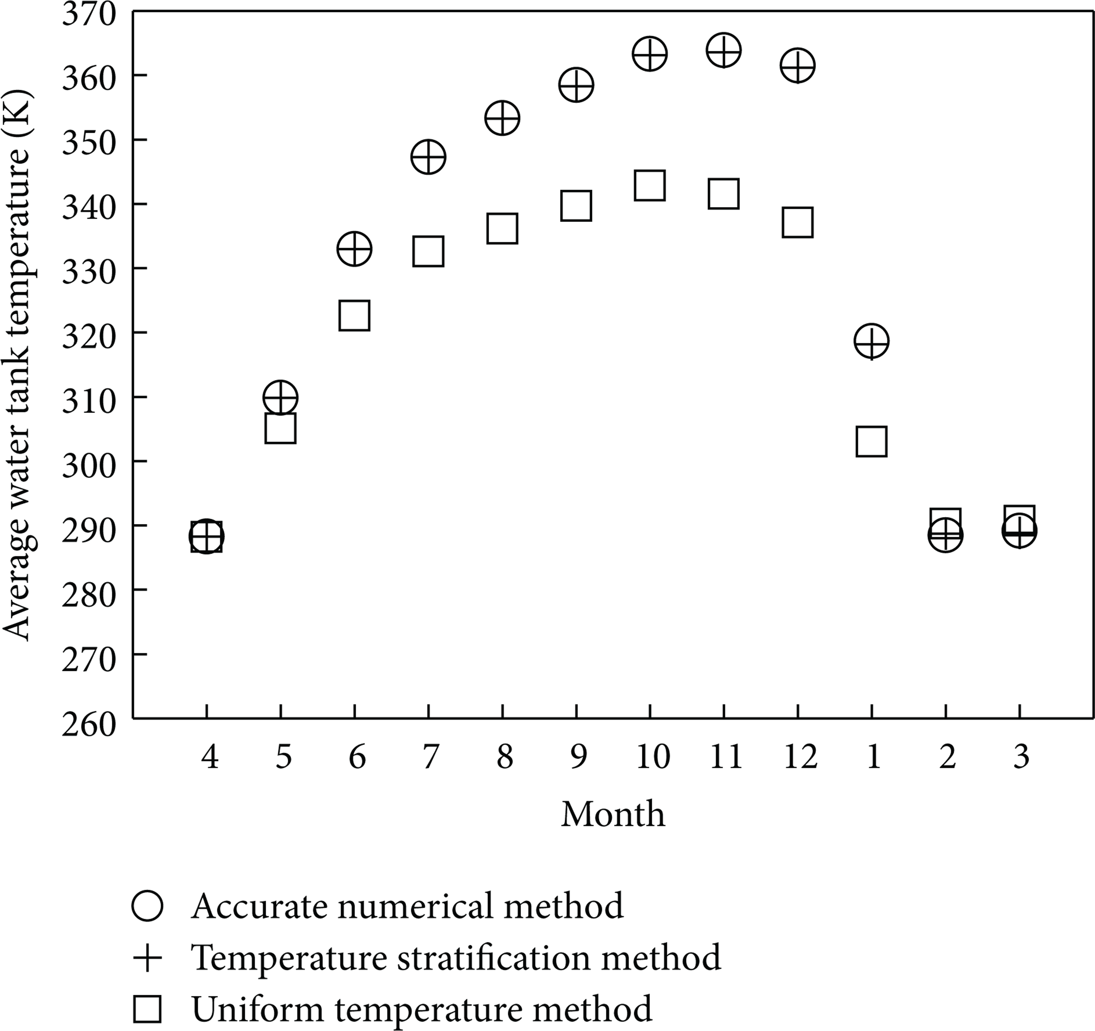
Monthly average water tank temperature computed by three different methods.
The average water tank temperature computed by the uniform temperature method is lower than that by the accurate numerical method. The difference is great with the maximum value as high as 24.38 K, as shown in Figure 4. The error of the yearly heat loss is as high as 267.0% compared with the accurate numerical method. The error of the yearly collection efficiency is 21.0%. The error of the yearly solar fraction is 7.4%, as shown in Table 2. Therefore, the deviations of the computation results by the uniform temperature method are great. Meanwhile, the computation time is similar to that of the temperature stratification method. Therefore, it is not recommended in this paper.
5. Performance Analysis on SHS-SWTHS
Based on the above analysis, the temperature stratification method is applied to analyze the influence of the embedded depth of water tank, the thickness of thermal insulation material, and the collection area on the performance of the SHS-SWTHS.
5.1. Influence of the Embedded Depth of Water Tank
The influence mechanism of the embedded depth of water tank is researched based on two typical soils: granite and sand. The corresponding thermal properties of these two soils are shown in Table 1. In this system, the collection area is 1200 m2 and the thickness of thermal insulation material is zero.
5.1.1. Granite Soil
Figure 5 shows the influences of different embedded depths on the monthly solar fraction, the monthly average water tank temperature, the monthly collected energy, and the monthly heat loss of water tank in granite soil. Here, the months shown in Figure 5 are different from the actual months. For example, April shown in this figure refers to the period from March 16th to April 15th. Thus, the period from April to November may be defined as nonheating period, and the period from December to next March may be defined as heating period. For convenience, the heat conducted from the water tank to the soil is named the heat loss of water tank, while the heat conducted from the soil to the water tank is named the reverse heat conduction of water tank hereinafter. When the temperature of the water tank is lower than that of the surrounding soil, the heat loss of water tank is negative; in other words, the reverse heat conduction of water tank is positive.

Influences of different embedded depths of water tank on the system performance in granite soil.
In the first month of heating period, that is, December, the monthly solar fraction as a constant of 100% is not influenced by the embedded depth of water tank, as shown in Figure 5(a). The reason is that, in the first month of heating period, the heat provided by the system comes from the heat stored in the water tank, the heat collected at the current month, and the reverse heat conduction of water tank. For the four different embedded depths of water tank, the heat of the abovementioned three parts is greater than the thermal load of the building at the current month. Therefore, the thermal load may be guaranteed.
In the second month of heating period, that is, January, the monthly solar fraction is lower than 100%, as shown in Figure 5(a). The reason is that after the heating for the first month of heating period, the temperature in the water tank is dramatically decreased. The stored heat as well as the collected heat and the reverse heat conduction cannot meet the thermal load of the building at the current month. According to Figure 5(a), with the increment of the embedded depth of water tank, the solar fraction is increased gradually. The reason is that the average water tank temperature and the reverse heat conduction increase with the increment of the embedding depth, as shown in Figures 5(b) and 5(d).
In the third and fourth months of heating period, that is, February and March, the monthly average water tank temperatures are both equal to the lowest temperature 288 K set by the system, as shown in Figure 5(b). The stored heat is zero, and the heat provided by the system only comes from the collected heat and the reverse heat conduction. Though the collected heats at different embedded depths are the same (as shown in Figure 5(c)), the reverse heat conduction increases with the increment of the embedded depth. Therefore, the solar fractions of February and March are increased with the increment of the embedded depth, as shown in Figure 5(a).
Generally, due to high thermal conductivity and heat capacity of granite soil, the heat loss of water tank is great and is influenced greatly by the embedded depth, as shown in Figure 5(d). With the increment of the embedded depth, the heat loss of water tank in nonheating period is decreased and the reverse heat conduction in heating period is increased. With the joint effect of these two factors, the solar fraction is increased gradually with the increment of embedded depth.
5.1.2. Sand Soil
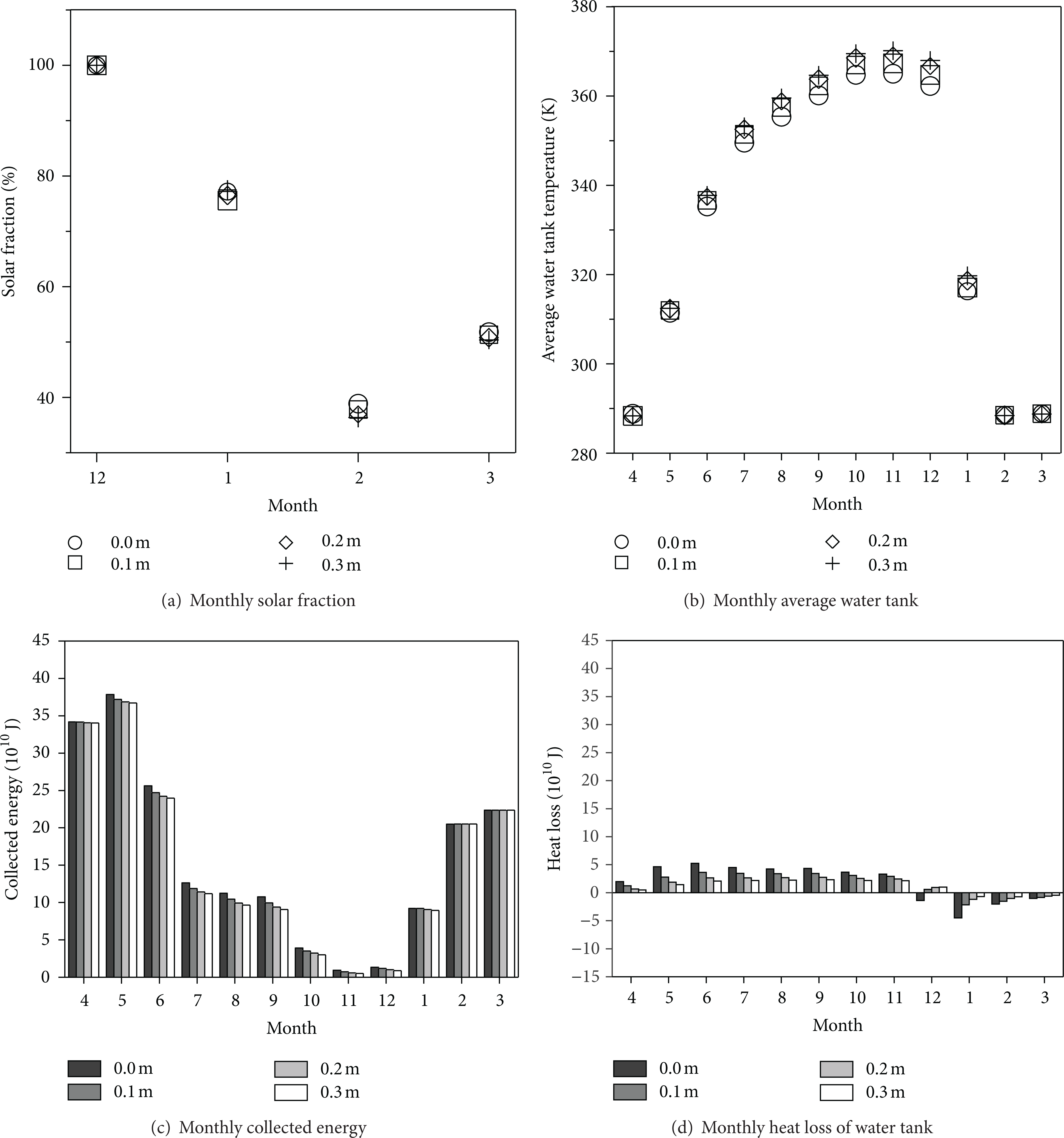
Figure 6 shows the influences of different embedded depths of water tank on the monthly solar fraction, the monthly average water tank temperature, the monthly collected energy, and the monthly heat loss of water tank in sand soil. Due to low thermal conductivity and heat capacity of sand soil, the heat loss of water tank is little and nearly is not influenced by the embedded depth, as shown in Figure 6(d). As a result, the influence of the embedded depth on the solar fraction is quite little, which almost remains unchanged.

Influences of different embedded depths of water tank on the system performance in sand soil.
5.1.3. Influence of Embedded Depth on Yearly Solar Fraction
Figure 7 shows the yearly solar fractions at different embedded depths of water tank based on two typical soils: granite and sand. Due to different thermal conductivities and specific heats, the influences of the embedded depths on the system performance are also different. In granite soil, the yearly solar fraction is increased with the increment of the embedded depth; however, the increasing amplitudes are lowered gradually. When the embedded depth is increased from 1 m to 8 m, the yearly solar fraction is increased by 23.6%. In sand soil, the influence of the embedded depth on the yearly solar fraction is quite little. When the embedded depth is increased from 1 m to 8 m, the yearly solar fraction is only increased by 3.2%. In addition, according to Figure 7, with the increment of the embedded depth, the yearly solar fractions in different soils tend to be consistent.

Yearly solar fractions at different embedded depths of water tank.
5.2. Influence of the Thickness of Thermal Insulation Material
The influence mechanism of the thickness of thermal insulation material is researched based on two typical soils: granite and sand. Glass wool is applied as the thermal insulation material. Its density is 135 kg·m−3, its specific heat is 1.8 × 10⁵ J·m−3·K−1, and its thermal conductivity is 0.045 W·m−1·K−1. In this system, the collection area is 1200 m2 and the embedded depth of water tank is 2 m.
5.2.1. Granite Soil
Figure 8 shows the influences of different thicknesses of thermal insulation material on the monthly solar fraction, the monthly average water tank temperature, the monthly collected energy, and the monthly heat loss of water tank in granite soil. Due to high thermal conductivity and heat capacity of the granite soil, the heat loss of water tank is great, which leads to great influence of the thickness of thermal insulation material on the system performance. During the nonheating period, with the increment of the thickness of thermal insulation material, the heat loss of water tank is lowered gradually, leading to gradual increment of the water tank temperature. This factor is favorable to improve the solar fraction. During the heating period, with the increment of the thickness of thermal insulation material, the reverse heat conduction is lowered gradually; in other words, the heat conducted from the soil to the water tank is lowered gradually. This factor is of no good to improve the solar fraction. Compared with the heat loss during the nonheating period, the reverse heat conduction during the heating period is relatively lower. Therefore, the first factor is dominant. Generally, for granite soil, with the increment of the thickness of thermal insulation material, the solar fraction is increased gradually, as shown in Figures 8(a) and 10.

Influences of different thicknesses of thermal insulation material on the system performance in granite soil.
5.2.2. Sand Soil
Figure 9 shows the influences of different thicknesses of thermal insulation material on the monthly solar fraction, the monthly average water tank temperature, the monthly collected energy, and the monthly heat loss of water tank in sand soil. Due to low thermal conductivity and heat capacity of sand soil, the heat loss of water tank is little. Meanwhile, due to the existence of the reverse heat conduction during the heating period, the increment of the thickness of thermal insulation material slightly decreases the solar fraction conversely, as shown in Figures 9(a) and 10.
Influences of different thicknesses of thermal insulation material on the system performance in sand soil.
Yearly solar fractions at different thicknesses of thermal insulation material.
5.2.3. Influence of Thickness of Thermal Insulation Material on Yearly Solar Fraction
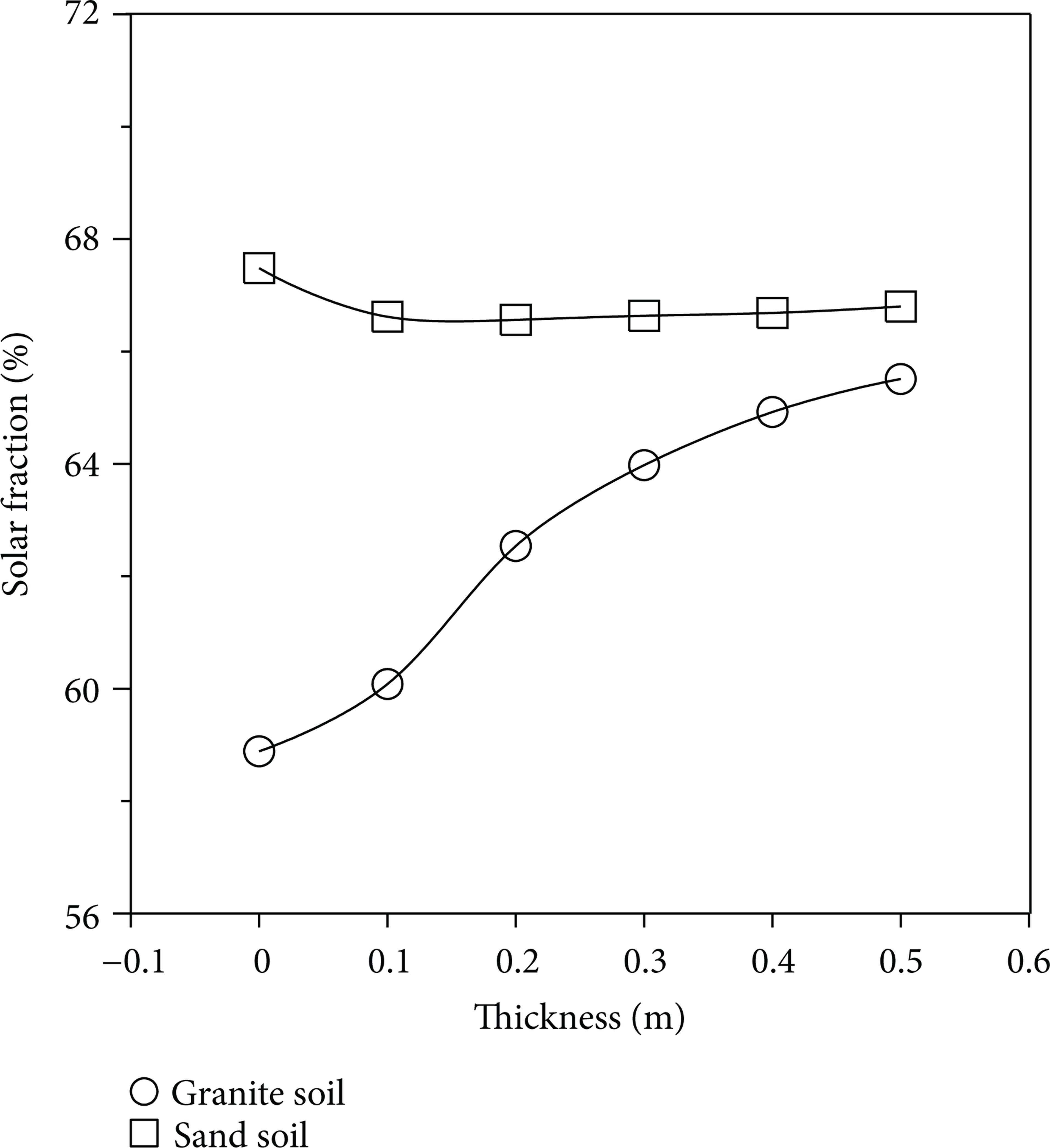
Figure 10 shows the yearly solar fractions at different thicknesses of thermal insulation material based on two typical soils: granite and sand. Due to different thermal conductivities and specific heats, the influences of the thicknesses of thermal insulation material on system performance are also different. In granite soil, the yearly solar fraction is increased with the increment of the thickness of thermal insulation material. When the thickness is increased from 0 m to 0.5 m, the yearly solar fraction is increased by 11.2%. Therefore, for the granite soil, the thermal insulation material with certain thickness should be laid to reduce the heat loss and increase the heat storage of the system. In sand soil, the influence of the thickness of thermal insulation material on the yearly solar fraction is quite little. Due to the existence of the reverse heat conduction during the heating period, the increment of the thickness slightly decreases the solar fraction conversely. When the thickness is increased from 0 m to 0.1 m, the yearly solar fraction is lowered by 1.2%, and further increment of the thickness bears hardly any influence on the system performance.
5.3. Influence of the Collection Area
The influences of the collection area on the system performance are also researched based on two typical soils: granite and sand. In this system, the embedded depth of water tank is 2 m and no thermal insulation material is applied. As an important influence factor, the collection area bears relatively great influence on the system performance. Figure 11 shows the influences of the collection area on the yearly solar fraction in two different soil conditions. The solar fraction of sand soil is greater than that of granite soil. With the increment of collection area, their solar fractions are increased gradually. However, the degree of growth is reduced gradually. When the collection area reaches 3200 m2, the solar fractions of both soil types are basically the same. At this point, the soil type has no influence on the system performance.

Influences of the collection area on the system performance.
6. Conclusion
In this paper we analyze and compare three different computational methods for the SHS-SWTHS, including the accurate numerical method, the temperature stratification method, and the uniform temperature method. The following conclusions can be obtained.
The accurate numerical method can accurately predict the performance of the system, but it takes about 4 to 5 weeks, which is too long and hard for the performance analysis of this system.
The temperature stratification method provides relatively accurate computation results and takes relatively short computation time, which is about 2 to 3 hours. Therefore, this method is most suitable for the performance analysis of this system.
The deviation of the computational results of the uniform temperature method is great, and the time consumed is similar to that of the temperature stratification method. Therefore, this method is not recommended herein.
Based on the above analysis and comparison, this paper applies the temperature stratification method to research the influences of the embedded depth of water tank, the thickness of thermal insulation material, and the collection area on the performance of the SHS-SWTHS and reaches the conclusions as follows.
For granite soil, due to high thermal conductivity and heat capacity, the heat loss of water tank is great and is influenced greatly by the embedded depth. With the increment of the embedded depth, the heat loss of water tank in nonheating period is reduced and the reverse heat conduction in heating period is increased. With the joint effect of these two factors, the solar fraction is increased gradually with the increment of the embedded depth. When the embedded depth is increased from 1 m to 8 m, the yearly solar fraction is increased by 23.6%. For sand soil, due to low thermal conductivity and heat capacity, the heat loss of water tank is little and nearly is not influenced by the embedded depth. When the embedded depth is increased from 1 m to 8 m, the yearly solar fraction is only increased by 3.2%.
For granite soil, with the increment of the thickness of thermal insulation material, on one hand, the heat loss of water tank during the nonheating period is lowered gradually, and on the other hand, the reverse heat conduction of water tank during the heating period is also reduced gradually. The influences of these two factors on the system performance are opposite. Compared with the heat loss in the nonheating period, the reverse heat conduction in the heating period is relatively less, leading to the increase of the yearly solar fraction with the increment of the thickness. When the thickness is increased from 0 m to 0.5 m, the yearly solar fraction is increased by 11.2%. For sand soil, due to the existence of the reverse heat conduction during the heating period, the increment of the thickness slightly lowers the solar fraction conversely. When the thickness is increased from 0 m to 0.1 m, the yearly solar fraction is lowered by 1.2%, and further increment of the thickness bears hardly any influence on the system performance.
With the increment of the collection area, the solar fractions of granite soil and sand soil are increased. However, the degree of growth is reduced gradually. When the collection area reaches 3200 m2, the solar fractions of both soil types are basically the same. At this point, the soil type has no influence on the system performance.
The above-mentioned researches provide a design basis for the related demonstration projects.
Conflict of Interests
Dongliang Sun, Jinliang Xu, and Peng Ding declare that the paper does not have any conflict of interests including any financial, personal, or other relationships with other people or organizations.
Footnotes
Nomenclature
Acknowledgments
This work was supported by the Young Scientists Fund of the National Natural Science Foundation of China (51106049), the Beijing Natural Science Foundation (3112022), the Hebei Natural Science Foundation (E2011502057), the National Basic Research Program of China (2011CB710703), the Fundamental Research Funds for the Central Universities (12MS44), and the 111 Project (B12034).