
Abstract
The dynamic test precision of the strapdown inertial measurement unit (SIMU) is the basis of estimating accurate motion of various vehicles such as warships, airplanes, spacecrafts, and missiles. So, it is paid great attention in the above fields to increase the dynamic precision of SIMU by decreasing the vibration of the vehicles acting on the SIMU. In this paper, based on the transfer matrix method for multibody system (MSTMM), the multibody system dynamics model of laser gyro strapdown inertial measurement unit (LGSIMU) is developed; the overall transfer equation of the system is deduced automatically. The computational results show that the frequency response function of the LGSIMU got by the proposed method and Newton-Euler method have good agreements. Further, the vibration reduction performance and the attitude error responses under harmonic and random excitations are analyzed. The proposed method provides a powerful technique for studying dynamics of LGSIMU because of using MSTMM and its following features: without the global dynamics equations of the system, high programming, low order of system matrix, and high computational speed.
1. Introduction
As there is no need to use external information for measurements, LGSIMU is widely used in tactical missiles, chariots, torpedoes, warships, airplanes, and so on [1–4]. Inertial measurement unit (IMU) usually operates in bad dynamic environment such as vibration, shock, and overload. For instance, broadband random excitations are produced by missiles in powered phase and reentry phase flights as a result of its engine thrust, jet noise, and turbulent boundary layer pressure. LGSIMU is fixed on the vehicle and undergoes the dynamic environments directly, which makes its operational environment very bad. Thus, its dynamic accuracy is declined.
In order to improve the dynamic accuracy, passive control method is usually adopted to restrain the dynamics response of LGSIMU system in the dynamic environment. The methods such as optimizing the bracket structure, matching the stiffness of isolator, and improving the sustaining mode are the main ways of passive control for the moment [5, 6]. Dynamics analysis is the basis of LGSIMU system design and error compensation. The simplified model which has two degrees of freedom is often used for the dynamics analysis of LGSIMU [7, 8]. Due to the excessive simplification, the model can not accurately reflect the influence of some realistic factors on the system dynamics performance. To analyze the dynamics performance of LGSIMU, attention is gradually paid to more realistic dynamics model, which is established based on the theory of multibody system dynamics. Liu et al. [9] used the theory of multibody system dynamics to establish the dynamics model of LGSIMU and analyze its dynamic characteristics. The ordinary dynamics methods are complicated due to the necessity to deduce the global dynamics equation and inconvenience for engineering applications. Rui et al. [10] put forward the transfer matrix method for multibody system (MSTMM) which does not need to establish the global dynamics equation and is highly stylized. MSTMM has been widely used in the fields of multiple launch rocket system, shipboard gun system, spacecraft, underwater towed system, and so on [11–15]. Yang et al. [16] used MSTMM to establish the dynamics model of LGSIMU and analyzed the effect of shock on the output precision. Ma et al. [17] used MSTMM to simulate the output power spectral density (PSD) of LGSIMU undergoing random excitation. Their works are both based on the body dynamics equations in MSTMM and modal superposition.
As a result of the bad dynamic environment, the shifting of gyroscope centroid and the drift produced by structure deformation greatly reduce the accuracy of strapdown IMU. However, due to a lack of the error analysis approach, ordinary inertial instruments can hardly compensate the error caused by dynamic environment. Savage [18] established the technique for compensating the attitude, velocity, and position errors under sinusoidal and random vibrations. Savage also presented the simplified dynamics model of strapdown IMU system which had two degrees of freedom including linear and angular motions. It provides an effective approach for error analysis and compensation, but the simplified model cannot reflect the reality perfectly. So it has great engineering significance to establish more realistic dynamics model for error analysis of strapdown IMU.
In this paper, MSTMM is used to establish more realistic dynamics model of LGSIMU system, elements transfer equations, and transfer matrices. The overall transfer equation and overall transfer matrix of the system are derived based on the MSTMM and its automatic deduction method [19]. The method for computing frequency response functions of LGSIMU system based on MSTMM is presented. The responses of LGSIMU system undergoing various sinusoidal and random excitations are obtained. Then the dynamics performance is analyzed. Combining the formulae of errors caused by vibration, the attitude errors of LGSIMU under sinusoidal and random vibrations are discussed. The methodology presented in this paper provides an effective technique for improving the dynamics performance of LGSIMU under dynamic environment.
2. Introduction to MSTMM: A Simple Example
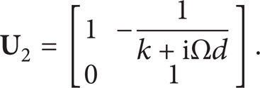
In order to describe the proposed method presented in the following sections conveniently, the simple system shown in Figure 1 is taken as an example. The system consists of lumped mass 1, spring-and-damper hinge 2, and base 3. The free boundary is numbered as 0. The mass of the lumped mass is m, and the stiffness and viscous coefficients of hinge 2 are k and d, respectively. The input and output of the system are the displacements of base 3 and lamped mass 1, respectively. The input of the system is assumed as harmonic excitation w = WeiΩt. In the following of this section, the frequency response function of the system will be derived by using MSTMM.
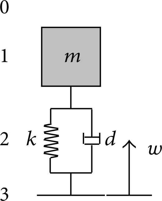
One degree of freedom system used to introduce MSTMM.
Using the sign conventions in [10], the positive directions of displacements and forces are shown in the free body diagrams of Figures 2 and 3. For the lumped mass, the displacements of output end and input end are equal, namely,

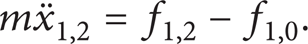
Applying Newton's second law of motion to the lumped mass yields
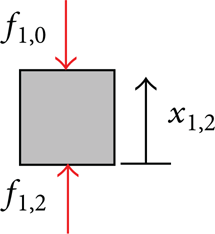
Free body diagram of mass 1.

Free body diagram of spring-and-damper hinge 2.
For the system undergoing harmonic excitation w = WeiΩt, its steady state responses can be written as x1,0 = X1,0eiΩt, x1,2 = X1,2eiΩt, f1,2 = F1,2eiΩt, f1,0 = F1,0eiΩt [20]. Substituting these equations into (1) and (2), the transfer equation of lumped mass 1 can be found as
where

For hinge 2, considering its constitutive relation, one can obtain

By substituting the steady state responses into (5), the transfer equation of hinge 2 can be acquired as

where the state vector also has the form
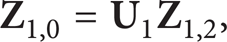
Combining (3) and (6), the overall transfer equation of the system can be obtained as

where

The boundary conditions of the system are

Substituting the boundary conditions into (8) yields

where

Solving (11), the unknown elements in the state vectors of boundary points can be obtained as
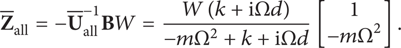
As a result, the frequency response function of the system is

Equation (14) can easily be verified using classical frequency response function analysis (i.e., Newton's second law of motion and Fourier transform).
3. Dynamics Model of LGSIMU System
According to the elements dynamics properties of LGSIMU system, the dynamics model shown in Figure 4 is established as a multibody system. The system can be divided into elements which can be modeled as follows: three gyros 1 ~ 3, platform 7, and foundation 12 are considered as rigid bodies, respectively; since the accelerometers are fixed on the platform and their masses are relatively small, they are included in the platform; the connections 4 ~ 6 between platform and gyros are considered as spatial spring-and-damper hinges; meanwhile, platform and foundation are linked by isolators 8 ~ 11, which are regarded as spring-and-damper hinges longitudinally vibrating in space. The motion of the vehicle is the input of LGSIMU system. The isolators 13 ~ 16 between foundation and platform are considered as spring-and-damper hinges longitudinally vibrating in space.
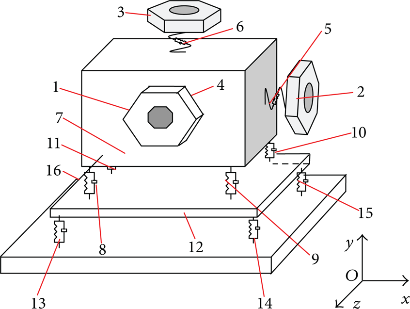
Dynamics model of LGSIMU system.
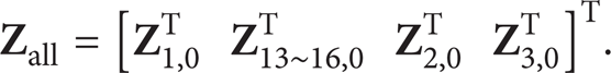
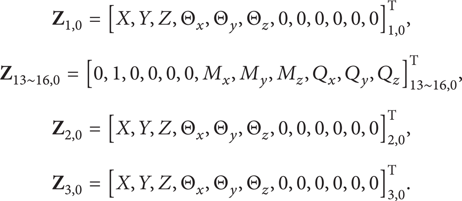
The inertial coordinate system shown in Figure 4 is used to describe the motion of elements. The state vectors of the input and output points of every element and the boundary points take the form

The state variables in the state vector are complex amplitudes of displacements, angular displacements, internal forces, and internal torques when the system undergoes harmonic excitation, respectively.
4. Topology Figure of the Dynamics Model of LGSIMU System
The dynamics model of LGSIMU system is constructed with dynamics elements including bodies and hinges. In order to describe the transfer relationship among the state vectors of elements in the system, the topology figure of the model will be used for deducing the overall transfer equation of LGSIMU system. Isolators 8 ~ 11 and 13 ~ 16 can be treated as one equivalent hinge element, respectively, which will be shown in Section 5.3; thus the dynamics model of LGSIMU system can be dealt with a tree system. Its topology figure can be got readily as illustrated in Figure 5.

Topology figure of LGSIMU system.
Besides the sign conventions introduced in [10], the sign conventions used in this paper are introduced as follows.
A circle ○ denotes a body element and the number inside it is the sequence number of the body element.
An arrow → denotes a hinge element and the transfer direction of state vectors, and the number beside it is the sequence number of the hinge element.
Body element 7 is dealt with three input ends and one output end and the other body elements are dealt with single input end and single output end.
For a nonboundary end, the first and second subscript i and j (i, j ≠ 0) in the state vector
The boundary end corresponding to element 1 is considered as the root, its state vector is denoted as
5. Transfer Equations and Transfer Matrices of LGSIMU Elements
5.1. Transfer Equations and Transfer Matrices of Gyros 1~3 and Foundation 12
The gyros 1 ~ 3 and foundation 12 are rigid bodies with single input end and single output end and their transfer equations are

where

where C denotes the mass center and m is the mass of rigid body,
5.2. Transfer Equations and Transfer Matrices of Spatial Spring-and-Damper Hinges 4~6
The transfer equations of elements 4 ~ 6 are

The transfer matrices are

where
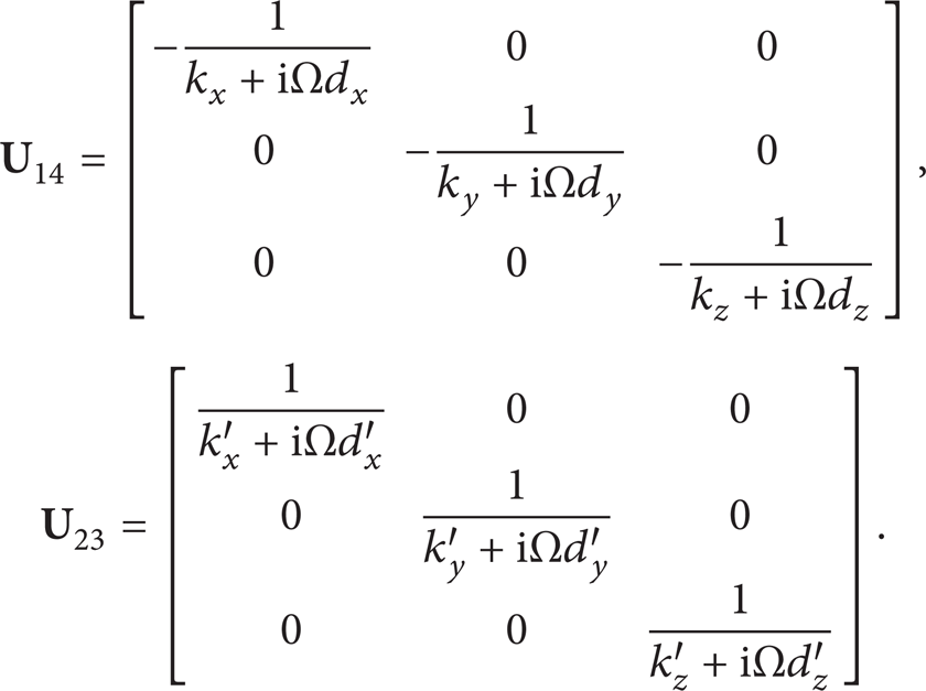
k x , k y , k z represent the stiffness coefficients of linear spring, k x ′, k y ′, k z ′ denote the stiffness coefficients of rotary spring, d x , d y , d z stand for the damping coefficients of linear damper, and d x ′, d y ′, d z ′ denote the damping coefficients of rotary damper, respectively.
5.3. Transfer Equations and Transfer Matrices of Isolators 8~11 and 13~16
As four isolators are sandwiched between two rigid bodies, they can be treated as one new element, namely, an equivalent spring-and-damper hinge with single input end and single output end. The input and output points of the new element can be selected at any positions on the two rigid bodies, respectively. Hereby, isolators 13~16 are taken as an example to deduce the transfer equation and transfer matrix of the new element. The input and output points of isolator 13 are selected as those of the new element, respectively. Two coordinate systems O1xyz and O2xyz shown in Figure 6 are introduced for deduction, whose origins are at the equilibrium positions of the input and output points of the new element. And their directions are the same with the coordinate system shown in Figure 4. The coordinates of the input points of isolators 13~16 in O1xyz are noted as (a i , b i , c i ) (i = 13 ~ 16). The same goes for their output points in O2xyz. The stiffness and damping coefficients of isolators 13~16 are (k xi , k yi , k zi ) and (d xi , d yi , d zi ) (i = 13 ~ 16), respectively. Simplify the system of forces acting on the input ends of isolators 13~16 into a system of forces only acting on the input point of the new element, and simplify the system of forces acting on the output ends of isolators 13 ~ 16 into a system of forces only acting on the output point of the new element. Further, since the principle vectors and principle moments of the two new systems of forces should be equal, the transfer equation of the equivalent spring-and-damper hinge can be obtained as
The transfer matrix is
where Ω is the frequency of harmonic excitation,

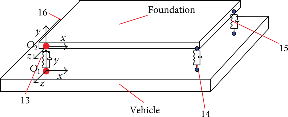
Equivalent model of isolators.
Replacing the stiffness coefficients (k
xi
, k
yi
, k
zi
) (i = 13 ~ 16) in
5.4. Transfer Equations and Transfer Matrices of Platform 7
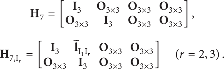
Platform 7 is considered as a rigid body with three input ends and single output end. The first input end is the connection point between platform 7 and isolator 8 and the second and third input points are the connection points between platform and gyros 2 ~ 3, respectively. The output point is the connection point between the platform and gyro 1. The transfer equation of platform 7 is

The transfer matrices are

The geometrical equations of platform 7 are

where
The notations in these matrices are similar to those in Section 5.1.
6. Automatic Deduction of the Overall Transfer Equation of LGSIMU System
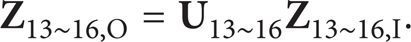
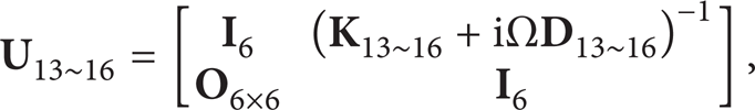
According to the topology figure and the automatic deduction method of MSTMM, one can obtain the overall transfer equation of LGSIMU system:

The overall transfer matrix is

where

7. Dynamic Responses of LGSIMU System
In order to introduce the method based on MSTMM to calculate the frequency response, the input and output are assumed as the displacements of the vehicle and the mass center of platform along y-axis, respectively. Setting the input to be a harmonic excitation w = eiΩt and according to the theory of vibration [20], the steady state response can be expressed as y7, C = Y7, CeiΩt and the complex amplitude Y7, C is the frequency response of LGSIMU system.
The boundary conditions of LGSIMU system are
Substituting these boundary conditions into (28) yields

where

Using the transfer equations of elements, one can easily obtain the frequency response function:

where
Similarly, the frequency response functions of other points can be got. Using the frequency response function, one can easily obtain the responses under sinusoidal and random excitations.
If the input is w = W sin (Ωt + α), the steady state response is

where
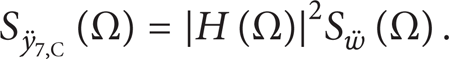
If the input is a stationary random excitation w(t) with PSD S w (Ω), the response is also a stationary random process and its PSD can be expressed as

For the case that the input is a stationary acceleration random excitation
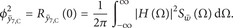
According to the Wiener-Khintchine theorem, the autocorrelation function of the response can be obtained as

Substituting (38) into (39) and setting τ = 0, the response mean square value can be written as
Similarly, the response PSDs and mean square values of other points can be readily achieved. Then one can analyze the dynamics performance and errors of LGSIMU system.
8. Error Analysis of LGSIMU
In order to improve the precision of LGSIMU in the dynamic environment, the errors must be compensated. According to the error analysis method presented in [18], the attitude errors are taken as examples to discuss the errors under sinusoidal and random vibrations in this section.
Assuming that LGSIMU system is excited by a sinusoidal excitation Wsin (Ωt + α), the angular motion response of the platform can be written as

where

The error caused by sinusoidal vibration is

where
If the response PSD of LGSIMU system undergoing random excitation is SO (Ω), the mean value of the attitude error caused by random vibration is

9. Numerical Example
For the LGSIMU system shown in Figure 4, the mass and inertia matrix of foundation 12 are given as

The mass and inertia matrix of platform 7 are

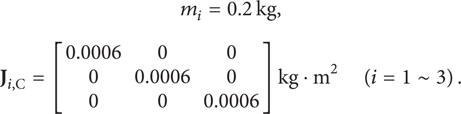
The masses and inertia matrices of gyros 1~3 are
The amplitude and phase frequency responses of the LGSIMU system got by the proposed method and Newton-Euler method are shown in Figures 7 and 8, respectively. It can be seen that the results got by the two methods have good agreements, which verifies the effectiveness of the proposed method. The attitude error rate under sinusoidal vibration is demonstrated in Figure 9, where the excitation frequency varies from 10 to 2000 Hz, the time interval is 20 ms, and the amplitude of excitation is 0.2 mm. From this figure, it can be concluded that when the excitation frequency is close to the natural frequencies of the LGSIMU system (25 Hz, 46 Hz, and 85 Hz), attitude error rate reaches maximum values. So the natural frequencies cannot be close to excitation frequency.

Amplitude frequency response.

Phase frequency response.

Attitude error rate under sinusoidal vibration.
Currently, the vibration reduction system of LGSIMU is in the development phase. Typically, its vibration reduction index is the root mean square value of acceleration response should be less than 2 g, and the PSD curve comes down rapidly after 200 Hz [21]. In the following, the dynamics response and the attitude error response of the LGSIMU system under random excitation is computed and analyzed. The PSD of the excitation is shown in Figure 10 and its root mean square value is 6.03 g. The PSD of the centroid acceleration of platform along y-axis is shown in Figure 11 and its root mean square value is 1.55 g. Since the root mean square value is less than 2 g and the PSD curve comes down rapidly after 200 Hz, the vibration reduction index is achieved. The isolators 8 ~ 11 are usually identical. The mean value of the attitude error rate versus the damping coefficient of isolators 8 ~ 11 is shown in Figure 12. The mean value of the attitude error rate decreases with the increasing of the damping coefficient. Consequently, within the index of vibration reduction, the damping coefficient of isolators should be as large as possible.

Input PSD.

Output PSD of platform along y-axis.

The mean values of attitude error rates.
10. Conclusion
Improving the precision of LGSIMU in a dynamic environment is an important problem over a long period of time. In this paper, the method for calculating the frequency response function of LGSIMU system is established by using MSTMM. Based on this method, the responses of LGSIMU system are obtained and the dynamics performance is discussed. Furthermore, the attitude errors under sinusoidal and random vibrations are calculated and the effect of damping coefficient on the errors is analyzed. The proposed method can also be used to analyze the velocity and position errors caused by vibration. The simulation results verify the effectiveness of the proposed method. Compared with the ordinary method, the proposed method does not need the global dynamics equation. It is also highly stylized, flexible for modeling, and easy to program and provides a powerful technique for studying the dynamics of LGSIMU.
Conflict of Interests
The authors declare that there is no conflict of interests regarding the publication of this paper.
Footnotes
Acknowledgments
The research was supported by Research Fund for the Doctoral Program of Higher Education of China (no. 20113219110025), Natural Science Foundation of China Government (no. 11102089), and Program for New Century Excellent Talents in University (NCET-10-0075).