
Abstract
In recent years, M2M networking is an active research topic in both academic and industrial fields. Home M2M networks, as an important branch of M2M networks, have attracted wide concerns for home application. In this paper, we first present a brief overview of home M2M networks. Then we introduce a hierarchical architecture of home M2M networks and describe the approach of devices management and services discovery. After that, we focus on the security authentication with centralized node and an improved method of available bandwidth measurement. With the centralized node, our system is more efficient and secure, because of efficient resource management and users' anonymity protection. Compared to existing bandwidth measurement methods, our method takes up less additional bandwidth, saves more time, and has a higher accuracy for measurement. Experiments are carried out to demonstrate the effectiveness and accuracy of the proposed scheme.
1. Introduction
Nowadays, home networks are rapidly developing to contain more and more digital living devices or terminals, including laptops, TVs, PCs, iPads, printers, smart phones, speakers, smart switches, and cameras. Machine-to-machine (M2M) technology allows machines or devices to directly communicate with each other without human intervention. It holds huge potentials for services improvement in a wide range of industries and daily life, such as smart grid, smart home, consumer electronics, security, and surveillance [1–7]. With the embedded devices widely used in home environment, home networks will shift from current human-to-human communications or machine-to-human communications to machine-to-machine pattern. Home M2M networks are characterized by low power, low cost, and low human intervention, which has huge potentials to improve service quality and reduce cost.
Home M2M network is a typical class of heterogeneous networks, which consists of a backbone network and multiple subnetworks. In the backbone network, as shown in Figure 1, there is a central machine called home gateway (HGW). It is used to connect the home network to outside world (e.g., Internet) and manage the whole network. The subnetworks can be classified into three complementary M2M subnetworks: body areas, personal areas, and local areas. Each subnetwork may be designed for a specific application. They work in a self-organized manner. There is a subgateway (SGW) in each subnetwork, which works as an endpoint to connect the subnetwork to the HGW as well as the backbone network. Both the HGW and SGW are logical entities. Their functionalities can be physically implemented in a single device (i.e., a cognitive gateway) [1].

The framework of home M2M networks.
Home M2M networking enables people to remotely control and monitor their homes in a more convenient way. It facilitates people to utilize portable devices, which are connected to Internet, to manage their in-home devices. However, machines in home environment are normally small and inexpensive, which put several constraints on M2M communications, including energy, computation, storage, and bandwidth. These constraints pose a number of unique challenges in the design of home M2M networks. For the aforementioned problem, some solutions have been proposed in the literature [1].
In the body areas, personal areas, or local areas, many applications highly depend on multimedia sharing. Three major standards, Universal Plug and Play (UPnP), Digital Living Network Alliance (DLNA) and Intelligent Grouping and Resource Sharing (IGRS), have been defined to facilitate multimedia discovering, searching, and sharing in home M2M networks [8–10]. These standards aim to establish a world of interconnected machines and a flexible environment of multimedia sharing. The specific contents of these standards will be explained in Section 3.
Although the previous solutions are valid in home M2M networks, they are not efficient and have some deficiencies, such as information repetition, information redundancy, security problem, and link overlap. In this paper, we present a centralized devices management approach, security authentication with centralized node and an improved bandwidth measurement method. These technologies can achieve the goal of efficient and secure resource management in home M2M networks.
The rest of the paper is organized as follows. We outline the system architecture in Section 2. In Section 3, we illustrate an approach of centralized node devices management and services discovering. Sections 4 and 5 introduce efficient security authentication with centralized node in detail and present an available bandwidth measurement method, respectively. Finally, the conclusion and the future work are presented in Section 6.
2. System Architecture
Home M2M networks can carry audio and video information and a variety of high-speed data transmission applications, including multimedia transmission and sharing, video monitoring, and home remote control. Home M2M networks can support data transmission of cable (such as Ethernet) and wireless (such as WLAN). It is based on IP network protocol and widely supports the interconnection between different devices in the home networks environment. It also supports the transparent transmission of multimedia and data services under varieties of network topologies.
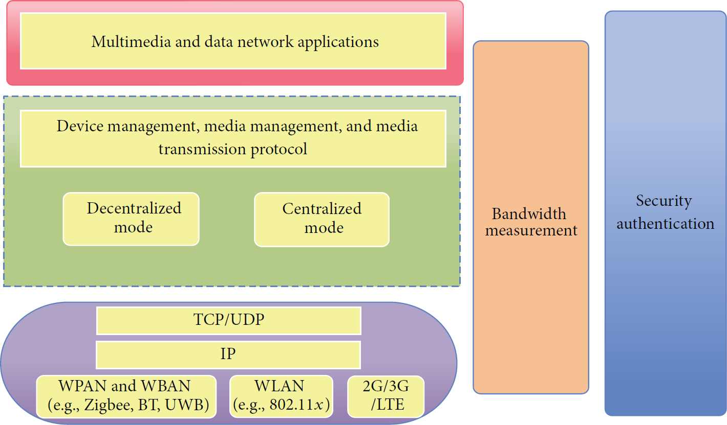
In this paper, the communication protocols of home networks contain relevant protocols from link layer to application layer, whose functional structure is shown in Figure 2. The network connection supports IP protocol, Ethernet and wireless LAN transmission. There are some application modules on the top of the network connection, including the applications of multimedia transmission and sharing, video monitoring, remote control, and cross-network communication. The application of multimedia transmission and sharing contains the functional components such as devices management, media management, media transmission, and media formats. This application also contains QoS and corresponding link protection mechanisms. It can achieve, in home environment, the goals of autodiscovery, autoconfiguration and automatic management among a variety of online devices. It establishes a seamless connection and implements comprehensive control, data transmission and sharing.
The home networks architecture.
In the physical layer and data link layer, home M2M networks can use wired or wireless way. When using wireless way, wireless LAN standards (such as IEEE802.11b, IEEE802.11g, IEEE802.11a, 3G, 2G, and LTE) should be followed. When using wired way, IEEE802.3 should be followed. Its physical layer reaches the requirement of data transmitted rate, which is 10 Mbps/100 Mbps. In the backbone network, the devices are combined to form the main family network by the gateway. It not only achieves the goal of networks configuration and management, but also joints the in-home networks and external networks.
The communication protocols of transport layer should use TCP/IP protocol, and all the multimedia and data devices at home should support the TCP/IP and UDP protocols. In the application layer, media and device management protocol provides an interoperability framework, which supports a variety of open standards. The framework is based on IEC 62481-1, and it defines the devices and software infrastructures to support interoperable building blocks, including the physical media, network transmission, media formats, streaming protocols, connection protection mechanism and QoS mechanisms. Through a seamless and interoperable network, this framework integrates Internet, mobile devices, and broadcast into the applications of home environment.
As shown in Figure 2, the applications are based on device management, media management, and media transmission protocol, including two modes: decentralized mode and centralized mode. In the decentralized mode, the devices, which need to share data or resources, can be automatically discovered and identified by each other. Then they establish a connection and transmit resources without the coordination and control of other nodes.
Based on the above framework, the multimedia transmission and sharing can be divided into three stages: devices management, media management and media transmission.
Device management is embodied in device addressing, network declaration, device discovery, service discovery, and call operation. Among them, the Dynamic Host Configuration Protocol (DHCP) addressing mechanism should be preferentially used in the device addressing. Devices can also manually set the IP addressing to ensure that there is no conflict between its address and other addresses. Media management is reflected in multimedia content identification, management, and distribution, which should support the IEC 62481-1, UPnP AV 1.0, and UPnP protocols. Media transmission, namely, the transmission of multimedia content, should support the IEC 62481-1, HTTP 1.0/1.1, IEC 62481-2 (media format protocol), optional support for DTCP-IP (connection protection agreement), and RTP/RTSP (media transfer protocol).
However, when there is a centralized node in the home M2M networks, the data or resources can be centrally managed. After modifying parts of the technical contents of decentralized mode, home networks with centralized node mode can be compatible with the decentralized mode.
Devices management contains the functions of devices addressing centralized node declaration, media devices registration and cancellation, devices discovery, service discovery, and call operation. Devices can also manually set the IP addressing to ensure that there is no conflict between its address and other addresses. Media management is reflected in multimedia contents identification, management, and distribution. The centralized mode mainly provides centralized devices directory, media resources, and information service. The media transmission of centralized node mode is the same as the decentralized mode.
As shown in Figure 2, there are still two parts in the framework: bandwidth measurement and security authentication. It is apparent that bandwidth measurement plays an important role in improving performance of system. In the heterogeneous home M2M networks, we need to find an efficient and flexible audio and video codec technology. Then it can utilize the limited bandwidth resource and achieve high-speed media information interconnection between different terminals in a more reasonable and efficient way. Furthermore, in order to coincide with the implementation of codec technology in the home networks, it also needs to improve appropriate technology of bandwidth monitoring and develop relevant description files of terminal devices. Measurement of network bandwidth allows us to know the current situation of remaining bandwidth. Then the data can be adaptively transmitted according to the remaining bandwidth. So we can take advantage of the limited bandwidth resources in more reasonable and more efficient way. In this paper, we propose an improved algorithm for measuring the network bandwidth, which is efficient and low complex. More details are described in Section 5.
Wireless technologies will considerably facilitate the home M2M networking. But security issues are the main challenges. Security authentication is the basis for the entire security architecture. In this paper, we propose an efficient wireless IP authentication method with user anonymity. If the machines want to obtain services from other legal machines, they first need to be authenticated by the centralized node. In the authentication process, the machines send real private information to the centralized node for authentication. After the security authentication, they can obtain a legal status. Then they can directly connect to the target machines by temporary keys. Compared to other existing methods, our method has the characteristics of higher safety, practicality, and efficiency.
As mentioned above, there are five functional modules in the home networks architecture. The internal connection between the different modules can be concluded as follows. The module of multimedia and data network application is based on the modules of media transmission protocol and communication protocols. The module of bandwidth measurement gets the available bandwidth of system in a high-speed and efficient way, and then the system can adaptively adjust the data transmission among different modules. What's more, the module of security authentication provides the protection of data transmission and communication among modules.
3. Devices Management and Services Discovery
Devices management is composed of device registration, device cancellation, devices and service discovery, invocation operation, event trigger, and so forth. Devices management is divided into decentralized mode and centralized mode.
3.1. Devices Management and Resource Management with Decentralized Node
In the mechanism of decentralized devices management, it needs to automatically discover, identify, and control the sharing resource. Currently, there are mainly three technologies to achieve the management as follows [1].
UPnP is essentially a technology in the application layer. It is based on TCP/IP protocol stacks in the lower layers. UPnP has two logical devices [11]: controlled devices (CDs) and control points (CPs). A CD can be a physical or logical network node to provide services. A CP can be a controller that discovers and controls devices. Once a new device is added to a network, it will firstly obtain its IP address and then advertise its services to CPs via a multicast Simple Service Discovery Protocol (SSDP). Once a new CP is added to a network, it shall search for devices of interest in the network. When a CP discovers a device, it may obtain the device's description file via the device's URL message. The CP keeps monitoring the state changes of the CDs. For home multimedia applications, the UPnP audio/video (AV) architecture is the standard for interoperability of multimedia systems among multimedia appliances. This architecture is based on the UPnP processes of discovery, description, control, and eventing, which facilitates a CP coordinating the flows of AV content between the source and sink devices. As a consequence, a consumer can retrieve any shared multimedia by running the CP in her own device and browsing the target media server.
In fact, based on the original network framework, the DLNA standard is an intermediate layer. In particular, the UPnP AV architecture is adopted by the DLNA Home Networked Device Interoperability Guidelines for media management and control between networked devices. End users also employ the UPnP mechanism to discover interoperable server devices in the network. The M2M connection is performed automatically without human intervention. The UPnP mechanism is used to search media content. The key of the DLNA protocol is media management. The DLNA standard defines two main classes of devices: digital media servers (DMSs) and digital media players (DMPs). A DMS is responsible for acquiring, recording, storing, and sharing the media content. A DMP does online searching and plays the media in a home network.
IGRS intends to offer seamless resource sharing and service collaboration among devices for communication terminals, computers, and consumer electronics for users at homes, offices, and public areas. IGRS includes three components: core protocols, application profiles, and basic applications. The core protocols define device grouping and the interaction between clients and services. The application profiles specify the service description. One of the key features of IGRS is taking into account the security issue. IGRS defines two layers of security protocols: the tunnel between devices and the session between users and services. IGRS categorizes the security mechanisms into three levels: identity and messages confirmation mechanism based on the symmetric key cryptosystem; identity authentication, encrypted message transmission, and message authentication based on the public key cryptosystem; identity authentication, encrypted message transmission, and message signature based on a trusted third party.
Although the previous technologies are good ways to manage the resource, they are not efficient and have some deficiencies, including information repetition, information redundancy, and link overlap. Moreover, there are still some problems, especially the security problems. For UPnP, there are two security flaws: the first one, the buffer has not been checked and restricted. The illegal users may get the privilege of controlling the entire system. It is very dangerous that the attackers get control of the computer ports, which may cause serious problems. The second one is that illegal user sends instructions to control a computer to download important data from system. Besides, the illegal user attacks the system, which may result in system crash. For the immaturity of DLNA and IGRS, the wide application cannot be accomplished. There are still some bottlenecks in the development. So we present a centralized management approach as follows.
3.2. Devices Management and Resource Management with Centralized Node
The devices management with centralized node is a centralized management approach, including three logical devices: centralized node (CN), controlled devices (CDs), and control points (CPs).
The CN refers to a device with the functions of security authentication, devices registration, and devices and services search as well as media information. The CN in the home M2M networks can monitor the devices declaration and registration information of CPs. It collects the information of devices and services and generates services registry list. The CN provides the CPs with accessing interfaces of service invocation and updates services registry list in the service description files. In particular, in this paper, the CN also has the function of security authentication. All the devices in the home M2M networks must be confirmed as safe devices before they begin to be linked or served. More details about the process of security authentication will be introduced in Section 4.
When the CN exists in the networks, the CN can finish multicast by the standard address and the port of 239.255.255.250:1900. It broadcasts its status and services to CDs and CPs. The CDs and CPs can be informed of the existence and basic information of CN by monitoring the packets of multicast ports.
When the CDs are online and they monitor the online declaration of CN, at the first time, they need to unicast registration information, which provides device information to the CN for security authentication and registration. After obtaining a legal identity, the devices periodically send the current status information to the CN and update the service status. When a device is going to exit the networks, it unicates a cancellation to the CN. Then the CN spreads the cancellation to all the devices and informs other CDs that this device has exited the networks.
What's more, the registration and cancellation process of CPs are similar to the process of CDs. Compared with the decentralized node mode, the CN mode has the advantages of highly efficiency, no repeated information, and more safety.
3.3. Device and Service Discovery
If a CP is on the line, it needs to monitor the multicast ports and find the CN. Then it sends the request information to CN for searching devices and discovering services. The processes of device discovery and service sharing are shown in Figures 3 and 4.
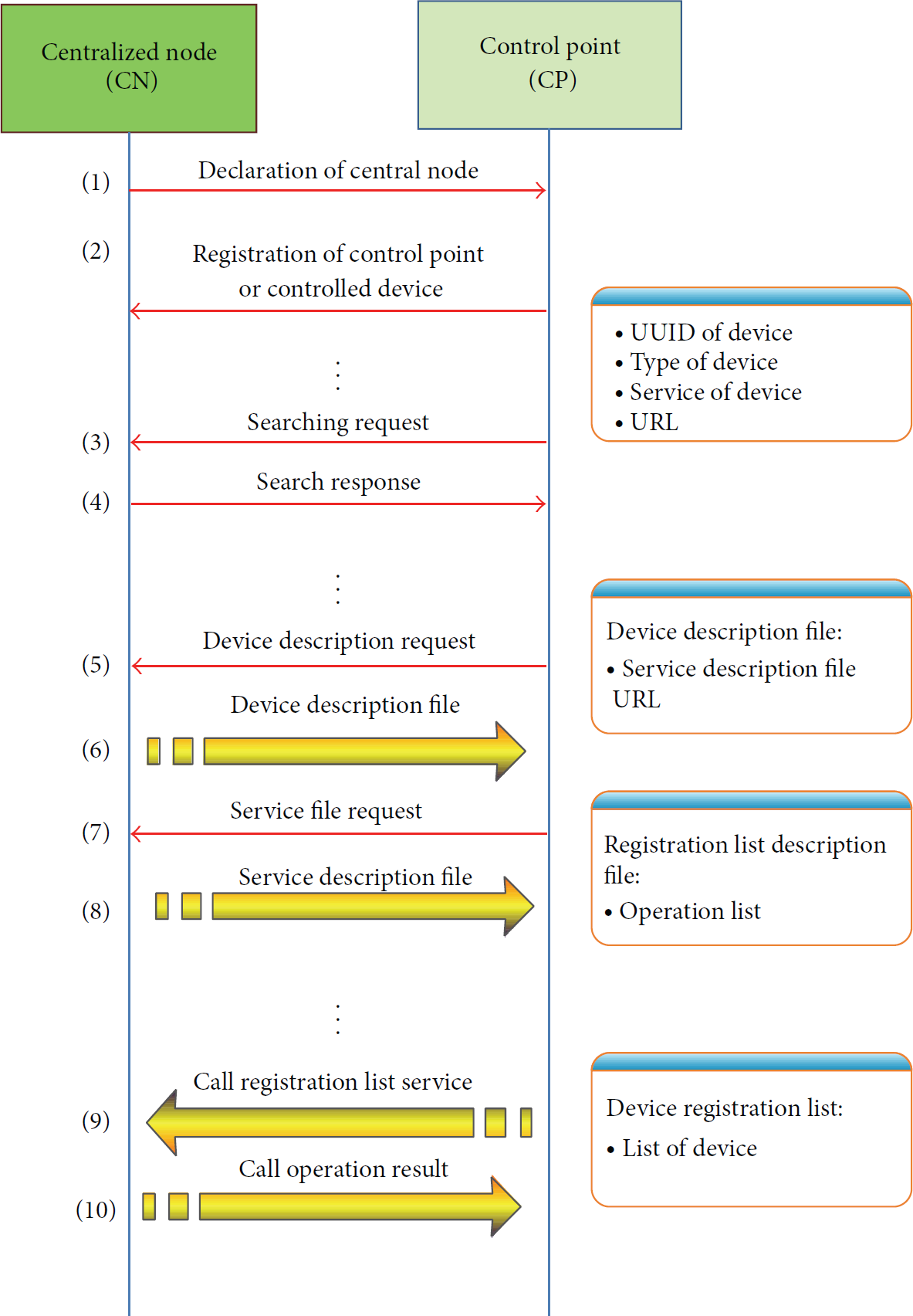
The process of device and service discovery.
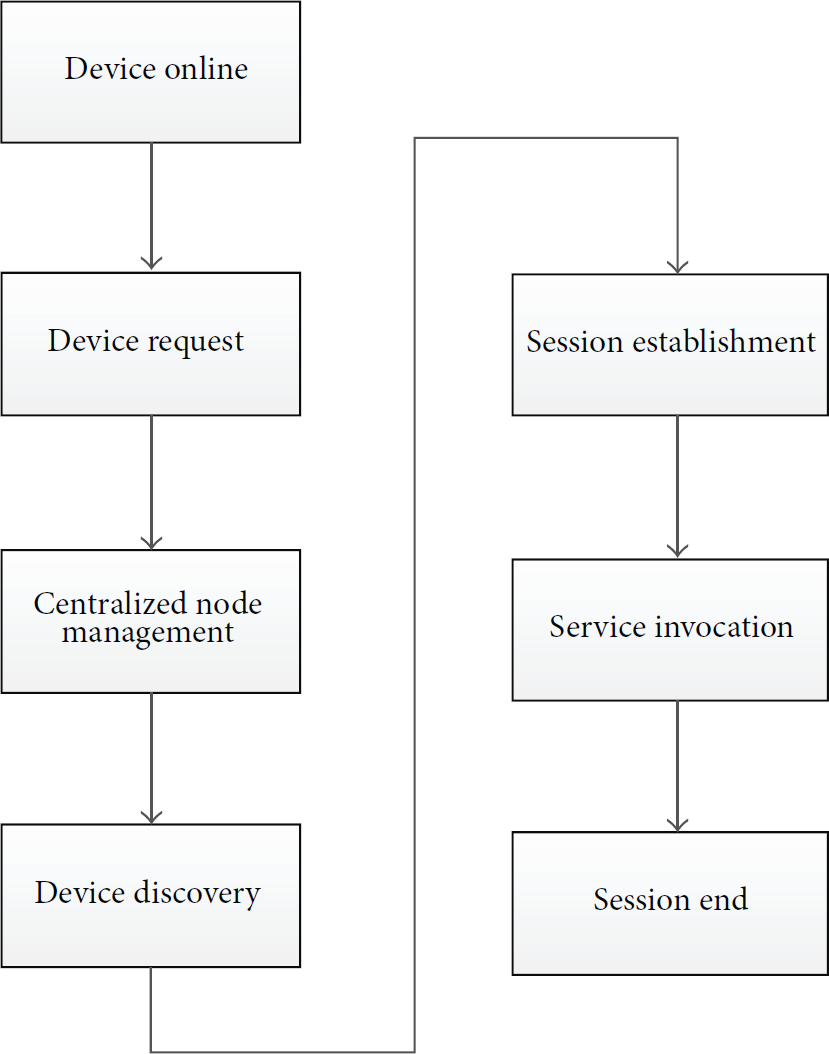
The process of device sharing.
After monitoring the declaration of CN, the CPs get the basic information of CN, such as devices' Universally Unique Identifier (UUID), devices type, service type, and device description file URL. The legal CPs or CDs register in the CN. CPs send the searching instructions to CN for finding out target devices. When the CN receives a legal request information, it will read the registration list and find out the target device, which matches with the request information. Then the CN sends response information to CPs. The CPs obtain the response information, and then they invoke related devices registry list to obtain all the basic information of registered devices in the CN. Thereby, they find the corresponding devices and services in the home M2M networks.
3.4. Session Establishment
After the requester finds the service provider, through the security authentication of CN, the CN provides the information of requester to provider, including the location, corresponding user identity, and authentication information. Then the service provider confirms the identity of requester by the previous information and determines the access rights of requester.
A session is the basis of service invocation. On one hand, the session indicates the security mechanism of service invocation. On the other hand, during the process of service invocation, if one part has message to inform others, it can use the notification mechanism. The session security mechanism is validated by the CN.
3.5. Service Invocation
If the service requester is successfully authenticated by the CN, then it is able to establish a session with the service provider and obtain the permissions of service. Through the interfaces of service description file provided by service provider, the service requester can use the service with the Simple Object Access Protocol (SOAP).
3.6. Session Ending
When the requester wants to exit the service, it can send a removed notification for ending the session. Moreover, the provider can also take the initiative to end the session and give the right of management back to the CN for the next turn of service.
In this part, a table is used to clarify the main features of proposed scheme, which is compared with UPNP, DLNA, and IGRS. The key parameters of comparison are listed in Table 1. From the table, we can see that the performance of proposed devices management approach is much better than the existing devices management schemes, such as UPNP, DLNA, and IGRS.
Scheme comparison.

4. Efficient Security Authentication with Centralized Node
The security authentication is the basis for the entire security system in home M2M networks. When we design wireless authentication protocols, we need to consider the following three main factors: (1) the client cannot use the algorithm with a large amount of calculation because of limited computing ability of the devices. (2) As the limitation of bandwidth in the wireless communication networks, it should reduce the length and number of exchanged information. (3) For the identity confidentiality, it should minimize the possibility of user's exposure [12].
For the previous security requirements, in this paper, we propose an efficient and secure authentication mechanism with anonymity. This mechanism achieves authentication and generates one-time keys between service requester and service provider. It is composed of three entities, that is, service requester (SR), centralized node (CN), service provider (SP).
Usually, there are two kinds of authentication polices without CN in home networks. One is that all the devices in the home networks share the same key. All the devices monitor and search the services by the same key. This policy is simple but unsafe and vulnerable. The other policy is that all the devices in the home networks have their own keys. Any device in the home networks must send its own public key to every other device to ensure the information encryption and transmission. Although it is safe, it is inefficient and complicated. For example, if a device has changed its public key, it has to multicast its new public key to every other device. It will be vulnerable and take up a lot of bandwidth resource. However, the devices in our policy have their own keys and a unique ID number provided by the CN. The devices only need to be authenticated by the CN and establish the communication with CN. Then they can be served in an efficient way without repeatedly mutual authentication among all the devices.
4.1. Symbols
The symbols, which may be used in the mechanism, are shown in Table 2.
Symbols.

4.2. Protocol Description
In this paper, there is a CN which discovers and manages devices in the home M2M networks. The node has a certification signed by the Certificate Authority (CA). The certification includes the public key and private key of CN, that is,
In the home M2M networks, a legal user must be registered in the CN. There is a big secret random number N with the length more than 100 bits in the CN. When a device is artificially added in the CN, the CN assigns a unique ID number to the device for calculating the key 
Then the CN sends a smart card, which stores the information of
As there are many kinds of devices and applications in the home M2M networks, in order to simplify the process, we take printing service as an example. In this scenario, the service requester (SR) is a laptop and the service provider (SP) is a printer. The steps of authentication are briefly described as follows.
4.3. The Steps of Registration
Step 1. As shown in Figure 5, we should manually enter the password of SP, that is,

The steps of registration.
Step 2. When the CN receives the information from printer, it checks the password whether it is right. If the checking is passed, the CN decrypts the information to get the
Step 3. After the printer receives information from CN, the printer checks whether the
Step 4. The CN gets the information from SP, and it checks the
For SP, the process of authentication and registration is finished by the previous four steps. Actually, the authentication and registration of SR are very similar to SP's process. But the
4.4. The Steps of Invocation Services
When a legal SR wants to be serviced, for example, the laptop needs to print. The steps of service are as follows. The process of services invocation is shown in Figure 6.

The steps of invocation services.
Step 1. The laptop generates a time stamp
Step 2. The CN receives the information and checks that whether the
Step 3. When the laptop gets the information from CN, it will check the
Step 4. The printer receives the information and checks the
Step 5. The laptop gets the information from the printer and then checks the
Step 6. The printer receives the information and checks the
4.5. Performance Evaluation and Analysis
To analyze the security performance of the previous policies without CN, we assume that an illegal user steals the public key and frequently sends a lot of illegal information to the target devices. It will bring much interference to the system and waste a lot of bandwidth. But our policy, during the service, adopts one-time keys, which are changing in every single time to minimize the possibility of key exposure. It can protect the true identity of device and achieve the users' anonymity. Meanwhile, the devices must pass the legal authentication before they are able to request the services. This policy not only improves the efficiency but also enhances the security.
Additionally, the time stamp used in above steps can improve the efficiency and safety. If the time stamp is checked to be illegal, the entities will not carry out the following steps including encryption and decryption. Thereby it can improve the system efficiency and reduce the waste of resources. What is more important, it can also prevent repeating attacks when the time stamp is checked as illegal.
4.6. Simulation
In this section, we provide some numerical examples to illustrate the performances of the previous proposed policies. In the simulation, we assume that there are some legal data that need to be transmitted in 1000 seconds. In this paper, the total value of legal data is set as 750 MB, and the bandwidth of system is set as 1 Mbps. We use Poisson model to characterize the data packets arrival process. The length of packets ranges from 1 to 200 KB randomly. The legal and illegal users transmit data in the same time. But once the illegal users begin to attack, the illegal data is five times the amount of legal data during the transmission. During the process of legal data transmission, the number of illegal users is increasing gradually. The number of illegal users increases from 1 to 8. We assume that there is only an illegal user after 50th seconds, and then the number of illegal users multiplies by two in each 100 seconds. Finally, there are 8 illegal users in the 350th seconds. After that, the number of illegal users always keeps in maximum value, which is 8, till the 1000th seconds. If there is no measures to protect the system, the bandwidth of system will be seriously occupied.
As shown in Figure 7, the vertical axis shows the sum of valid transmitted data. And the horizontal axis shows the time. In this simulation, we evaluate the performance of different policies by the sum of valid transmitted data. The larger value of the sum is, the better performance of the policy is. It means that the system is less influenced by the attacks of illegal users.

Four kinds of security authentication policies performance.
From Figure 7, the line of centralized node with authentication almost linearly increases during 1000 seconds. It is because that the invalid data of illegal users is detected and filtered by the process of registration in CN and the authentication among devices. The target device receives all the legal data without interference, which is about 740 MB. As the total value of valid data is 750 MB, the ratio of received valid data is over 99%. The decentralized node with authentication almost linearly increases to 602 MB in 1000th second, in which the ratio of received valid data is about 80%. Without CN's management, the invalid data is only filtered by the authentication among devices. So some invalid data is still received by the target device, which takes up a part of available bandwidth. In addition, the centralized node without authentication is similar to the decentralized node with authentication, which is linearly increasing to 340 MB in 1000th second. Due to the use of registration in CN, a portion of invalid data is filtered by the centralized node. So the ratio of received valid data is about 45.3%. However, it is shown that the decentralized node without authentication transmits the minimum valid data, whose final value is only 100 MB. The ratio of received valid data is only 13%. When the illegal users increas, this curve has a quick decay. It is because that the target device receives both valid and invalid data in the same time. But the illegal data takes up most of the bandwidth, which has a deep impact on legal data transmission. The policy of centralized node with authentication is much better than the other three policies, which demonstrates the superiority of our security authentication policy.
5. Bandwidth Measurement
Bandwidth measurement is another enabling technology to enhance the networking efficiency. Usually, there are many data transmission applications in the home M2M networks. We take the multimedia transmission as an example to illustrate the bandwidth measurement algorithm.
5.1. System Model for Adaptive Multimedia Transmission
The basic framework, which has been adopted for the media transmission system, is shown in Figure 8. We can see that there are mainly two modules in the system: available bandwidth measurement module (ABWM module) and scalable video coding module (SVC module) [13]. Video data is encoded by the SVC module and then sent to the network according to the current measurement result of the ABWM module. SVC is also called layered coding, whose main concept is to divide the original video stream into two or more streams, called layers.
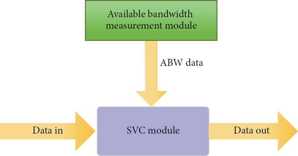
The framework of media transmission system.
Before the transmitter sends the video stream to the receiver, available bandwidth measurement algorithm (e.g., Pathload [14], PathChirp [15], etc.) will be used to measure the available bandwidth between the transmitter and receiver. Then the base layer data will be sent to the client to ensure that the receiver can get basic video image information. After that, the enhancement layers will be sent according to the current available bandwidth. If the available bandwidth between the transmitter and receiver is very low, the transmitter will not send enhancement layers or just send a few enhancement layers to the receiver. Otherwise, if the available bandwidth between the transmitter and receiver is high, then the transmitter will send all the enhancement layers to the receiver to ensure that the receiver can receive the video with the best quality.
5.2. Available Bandwidth Measurement Algorithms
(1) The Definition of Available Bandwidth. Available bandwidth [16, 17] is the maximum data transmission rate that can be provided for a new single connection without affecting the transmission rate of the existing connections.
Assuming that the cross-traffic stays constant in a short time T, 
(2) the Category of The Available Bandwidth Measurement Algorithms. Usually, the available bandwidth measurement algorithms are divided into two classes: direct probing and iterative probing.
Probe Gap Model (PGM) is one of the direct probing models. It estimates the available bandwidth through the changes of the gap in the probing packet pair. The source host sends the probing packet train at the rate of 
Iterative probing measures the available bandwidth via high speed probing packet trains which will cause congestion in the path. Bursty packet trains will be sent to the network. If the rate between two packets is higher than the available bandwidth, congestion will occur in the path instantaneously. The timing space between probing packets will be changed. We can estimate the available bandwidth by analyzing these delay characteristics of probing packets. The measurement process is actually an iterative process of changing the rate of the packet trains continually. Therefore, iterative probing is also called (PRM) Probe Rate Model. Unlike PGM, iterative probing does not require the tight link bandwidth
(3) The PathChirp Algorithm. PathChirp [15] is a kind of iterative probing. PathChirp estimates the available bandwidth along a path by sending a number of packet chirps from transmitter to receiver and then the receiver, will get the available bandwidth of the path by analyzing the delay characteristic of the packets. The transmitter sends the chirps as shown in Figure 9. One chirp consists of N exponentially spaced packets. Ideally, the queuing delay of the packets that the receiver received will monotonously increase from packet K. But due to bursty traffic, queuing delays will typically not increase monotonically within a chirp. Figure 10 shows the queuing delays of a typical chirp train [15]. We refer to such a plot as a queuing delay signature.

Chirp probe train.

A typical queuing delay signature.
PathChirp uses the shape of the signature to make an estimation 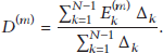
Compared with other existing measurement algorithms, PathChirp has less influence on network, consumes less time for measurement, and has a high accuracy. It is suitable for both wired or wireless measurement environments.
(4) Experiment Results. We use PathChirp algorithm to measure the available bandwidth in home network. In this measurement, the link bandwidth of the home work is about 85 Mbps. One host runs the transmitter program, and another host runs the receiver. We also add some cross-traffic (about 10 Mbps) during the measurement period. Table 3 and Figure 11 show the result.
Experiment result.

Experiment result.
In Figure 11, the vertical axis shows the values of available bandwidth. The horizontal axis shows the times. In this paper, we carry out five measurements by using the PathChirp algorithm. The circle points are on behalf of the values of actual available bandwidth, and the star points are on behalf of PathChirp algorithm's measurement values. We evaluate the performance of PathChirp algorithm by comparing the measurement values with the values of actual available bandwidth.
For comparison, we use the actual values minus the corresponding measurement values. From Table 3 and Figure 11, we can see that the maximum and minimum of errors are 6.23 MB and 0.145 MB, respectively. The average error value of measurements is 3.38 MB. In short, the measurement results are closed to the real value of the network. This means that the accuracy of the measurement algorithm is high. The PathChirp algorithm can basically reflect the current situation of the available bandwidth. Therefore, we can use it to measure the available bandwidth and monitor the network status in home networks.
6. Conclusion and Future Work
This paper proposes an efficient and secure resource management framework in home M2M networks. In this paper, there is a centralized node in the system architecture. We present a security authentication approach, which is a policy of centralized authentication. It can protect the true identity of devices and achieve the requirement of users' anonymity. Our system is more efficient and secure, because of efficient management of keys and resource allocation. We also adopt an available bandwidth measurement algorithm. It can adaptively measure the bandwidth and dynamically adjust the resource, which has less influence on network, consumes less time for measurement, and has a higher accuracy. Due to the above technologies, we can achieve the goal of efficient and secure resource management in home M2M networks. For future work, we will add the digital signatures of devices to information, which can further improve the security of the system.
Footnotes
Acknowledgments
This research is partially supported by programs of NSFC (grant nos. 61370159, U1035001, U1201253, and 61203117), the Opening Project of Key Lab. of Cognitive Radio and Information Processing (GUET), Ministry of Education (grant no. 2011KF06), and key research projects supported by the Department of Science and Technology of Guangdong Province (grant nos. 2012B090600053, 2011A090100039, 2011B090300108, 2011A080803009, 2011A011305003, 2011B090400360, and 2012B031800215).