
Abstract
The paper presents the pressed joint technology using forming process with or without additional fastener. The capabilities for increasing the load-carrying ability of mechanical joints by applying special rivets and dies were presented. The experimental research focused on joining steel sheet metal made of different materials. The joint forming was performed with the solid round die and rectangular split die for riveted joint forming. The load-carrying ability of joints was evaluated by measuring the maximum load force in the shearing test in the tensile testing machine. The effect of joint forming process on joined material strain was compared by measuring the microhardness of the joints.
1. Introduction
The assembly process development is driven by the automotive industry, especially by companies manufacturing car body elements. These companies are involved in developing and implementing new solutions which are more environmentally friendly.
The processes of plastic joining of sheet metal constructions are even more successful. These processes belong among “white manufacturing processes” [1]. Unlike spot welding and welding, they do not emit dangerous vapors [2]. Mechanical joining of sheet metals is commonly used to manufacture the controlled crush zones elements in cars [3, 4].
In most clinching joint cases, the static strength is lower than that for spot weld joints. The clinching joint strength can be increased by using higher forming force in order to achieve decreased bottom thickness “X” of the cap part of the joint [5]. Another method is using the modified forming with the rivet [6].
The mechanical joints are competitive comparing to conventional joints and can be used successfully while joining thin-walled sheet metal profiles in the framework construction houses [7–10].
The tool geometry must be selected properly in order to provide optimum joint forming conditions while joining materials. The selection of optimal values is a problem mentioned in papers developed among the others by Oudjene et al. [11], Coppieters et al. [12], Roux and Bouchard [13].
First works on experimental researches of forming joints using round segmented die were presented by Lambiase in two papers [14, 15]. This is quite a new look on clinching joint forming capability.
The mechanical joint forming using the nonround split die with rivet is not a well-known problem.
The most up-to-date papers and the only ones on such joints forming capability are papers presented by Mucha, Kaščák, and Spišák [6]. Another paper presenting the effectiveness of this joining method is the paper published by Mucha and Witkowski [10].
Thus the authors decided to present results of joint researches conducted by Technical University of Košice and Rzeszów University of Technology.
2. Clinch Riveting Process
The joining process in the ClinchRivet (CR) technology is similar to the self-pierce riveting (SPR) and clinching (CL). The lock consisting of joined sheet metals is created by the plastic deformation of a solid rivet [16]. For CL technology, the lock is formed by the rigid punch along with relevant die. The upper sheet metal is perforated while pressing the rivet with the self-pierce riveting (SPR) technology. The sheet metals are locked by anchoring the rivet in the lower sheet metal.
Whereas, CR technology entails pressing the solid rivet and anchoring this rivet in the upper sheet metal. The upper sheet metal is anchored in the lower sheet material (Figure 1). In this way, the joint is created.

Clinch riveting process: (a) joint forming and (b) general section of a clinched joint.
No fastener is required in the CL joint. SPR and CR require specially selected rivets: the tubular and solid one.
The material lock is created in CR joint, as this is also the case for CL joint. The measurable lock parameters are t n and t u (Figure 1(b)). The strength and the destruction mechanism of CR joint, similarly to CL joint, depend mainly on created lock size and the t n and t u ratio. The CR joint bottom thickness is a critical area for joint tightness. Figure 1(b) shows how to measure the joint bottom thickness.
3. Materials and Methods
The research experiments were conducted in order to determine the joining capability of different material by ClinchRivet riveting technology developed by Tox Pressotechnik [17].
The maximum joint load-carrying ability increase range and the joint structure hardness were observed. The joint quality evaluation was performed visually (externally) and internally by preparing metallographic microsections. For various joints, the lock parameters t s and t n were also measured. For selected variants of CR and CL joints the above mentioned lock parameters were compared.
The maximum strength of clinching joint was compared with ClinchRivet joint.
3.1. Sheets Material
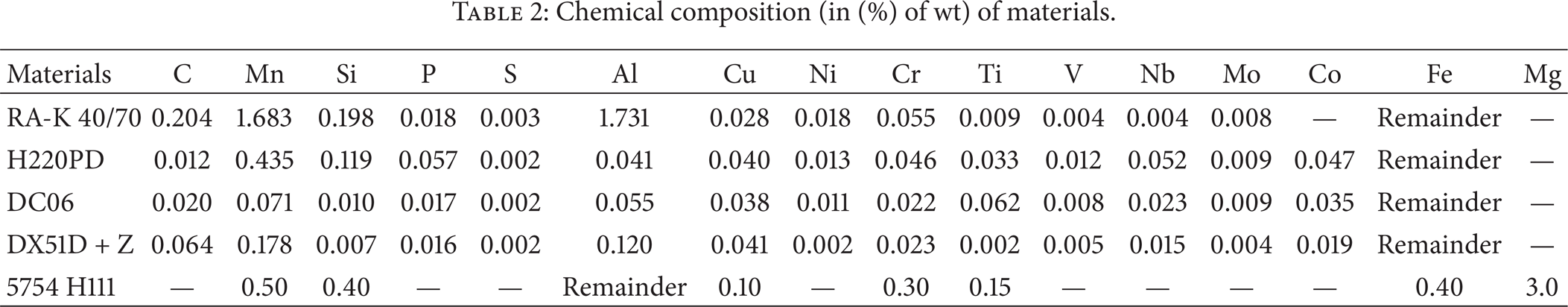
The examined sheet metals were made of steel and aluminum alloy. The steel sheet plates of 0.8 mm thickness are used in car body elements in Volkswagen Group car assembly plant, Skoda Mlada Boleslav in Bratislava. For comparison purposes, the aluminum alloy 5754 sheet metal of the same thickness in H111 state, material number 3.3535, was used. Different mechanical properties enabled examining the joint forming capability by straining the rivet being pressed. The chemical composition and mechanical properties were presented in Tables 1 and 2.
Basic mechanical properties of materials sheets.

Chemical composition (in (%) of wt) of materials.
3.2. The Rivet and Joint Forming Tools
Single rivet type of specified geometry (Figure 2) was used in joint forming; an average hardness of the steel rivet in five measurements was 357 HV0.1. The used rivet was made of material designated by the catalog number A5'5-2Al by TOX Pressotechnik. Main alloy additives in the chemical composition, besides carbon, are 0.35% Al and 1.5% Mn. The microstructure of the rivet material (zoom ×500) is presented in Figure 3.

Rivets used in CR joint forming (a) and basic geometry (b).

Rivet material microstructure (×500).
For all ClinchRivet rivet joining cases, we used the same die (Figure 4(a)). In the joining experiment, the Tox Pressotechnik die, catalog number TOX SKB 14.180.246182, was used.

Dies for joint forming: (a) CR, (b) CL, and (c) geometry tools.
The clinching joint (CL) was created with punch and die (Figure 4(b)) manufactured especially for thin sheet metal joining. These tools are used in the laboratory of Department of Technologies and Materials at the Technical University of Košice. The basic tool geometry was presented in Figure 4(c).
The CR rivet diameter was close to the diameter of die forming the CL joint.
Smaller die and punch diameters are dedicated in CL process for thin sheet metals. They result in a better lock in the overpress (cap part of the joint which is formed by the punch pressing the joined materials into the die) [18]. Forming joints of sheet metal of different thickness are often accompanied by the material fracture. The tool geometry selection is especially important for thin sheet metals [19].
The die with CR rivet is more universal and forms high quality joints. The punch head with automatic rivet feeder was used while forming CR joints.
Joint forming was performed on the CMB frame press with an electric EMPK drive made by Tox Pressotechnik, maximum loading force of 100 kN. EMPK servo drive enables positioning the punch with 0.01 mm accuracy and measuring the joint forming force versus travel at maximum error of 0.5% force value. In all joining the rivet (CR) was pressed in order to achieve the flat surface of the upper sheet metal. The final punch position was set in order to achieve the distance between the die face and the punch face that equals the sum of sheet metal thicknesses. The distance value was defined in the control software of the press drive. This value was identical for all material combinations. Thus for different sheet materials different forming force was achieved.
CL joints were created for identical X value of the bottom thickness. The value recommended by the tool manufacturers equals 25% of sum of joined sheet thicknesses. The same value was used in the experiment.
3.3. Joint Specimens and Combinations
The overlap joint specimens (Figure 5) were prepared for shearing test; 7 pieces for all arrangement. The force versus punch movement while forming was recorded.
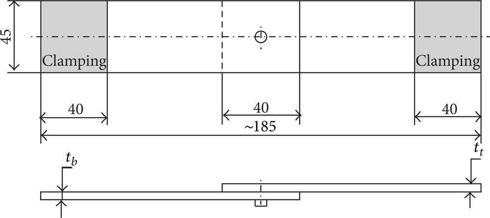
Overlap joint for shearing strength tests.
The correct joint structure depends on many factors, including tool geometry, the strain hardening characteristics and material of sheet metal being joined, and rivet. The material flow while clinching process is limited to a small region around tools [20]. The optimization of tool geometry for clinching process requires detailed knowledge on the material strain hardening characteristics. This issue was comprehensively presented by Coppieters et al. [21].
This paper focuses on effect of material type change on internal joint structure forming. Examined sheet plate arrangements are presented in Table 3.
Combination of materials.

CR joints were performed for all material variants from A to F and CL joints for variants A, C, and F.
3.4. Shear Tests and Microhardness
The shearing tests were performed on a universal tensile testing machine equipped with extensometer system and the sensor head for force measurements. The results were recorded by recording the joint shearing curve course in the static tension test of an overlap joint at 10 mm/min.
Sometimes the internal sheet metal defects cause the higher or lower joint strength. Higher differences of maximum joint shearing force were recorded in some cases during the experiment. Two most distinctive results were rejected, and subsequently the average value of 5 tests was calculated. To achieve the same test amount for each joining combination, the average of five results was accounted for.
The quality evaluation of clinching joints included metallographic and microhardness analyses. The 1N load was applied in measurements for about 15 s. The measurements were performed for specified locations on the joint cross-section (Figures 6(a) and 6(b)). Then the microsections were repolished and other measurements were performed. Three measurements were performed in each location. For tested materials, the starting material's microhardness was measured.

Microhardness measurement locations in joined sheet metals for (a) CR, (b) CL, and (c) rivet—CR.
In order to compare the rivet and sheet material strain hardening change, the microhardness measurement (Figure 6(c)) of the rivet in the sheet joint made of H220PD was performed.
4. Results and Discussion
The die with movable segments is required for CR joining (Figure 4(a)). Joining without a rivet requires no such a solution and the solid rigid die may be used (Figure 4(b)). Thus, the bulge of various shapes on the die contact side is achieved (Figure 7).
The bulge of a joint formed in CR process for H220PD material (a) and DC06 (c) and CL process for H220PD material (b) and DC06 (d).
H220PD steel features the highest yield stress among all examined sheet materials. Large radial sheet metal plane transition into the bulge is visible right at the joint base (Figure 7(a)). On the other hand, in CL joint, the huge material breakdown may be observed on the bulge circumference (Figure 7(b)). Visible grooves show the difficult plastic material flow while pressing it into the die impression.
The bulge size in the die groove depends on the material type and tool geometry. This problem was clarified in several papers developed among the others by Mucha [5], Oudjene et al. [11], Jayasekara et al. [18], Lebaal et al. [19], Lee et al. [22], and Coppieters et al. [23]. On the other hand, the ClinchRivet joint forming problem is rarely known.
For a material of lower yield stress and better formability, more correct joint forming is achieved both for CR (Figure 7(c)) and CL (Figure 7(d)).
Forming CR joints using DX51D + Z/RA-K 40/70 required the highest pressing force, whereas the highest joint shearing force was achieved for H220PD/H220PD (Figure 8).

The forming force (F f ) and maximum joint shearing strength CR (F s ) for various materials and their combinations—average values.
The forming force generated by the riveting machine drive significantly deforms the riveting press frame [24]. High strain of the joining device's frame may lead to asymmetric joint forming.
Depending on sheet metal material type, for the same rivet different maximum shearing force and the shearing curve are achieved (Figure 9).
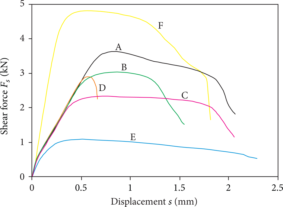
The example shearing curves of the ClinchRivet (CR) joint for sheet metal combination.
The maximum load-carrying ability of joints prepared with CR technology is several times higher comparing to joints prepared with CL technology (Figure 10) making the joint with rivet (CR) features a better forming, thus resulting in higher strength. Note the very high energy consumption of CR forming process comparing to CL technology without rivet. For sheet metal material layout “A,” the forming force was 22 kN, for layout “C” F f = 20 kN, and for layout “F” F f = 24 kN.

Comparison of an example shearing curve for joints made of DX51D (A-red), DC06 (C-blue), and H220PD (F-black).
The typical feature of CR joint is that the overpress is stiffened by the pressed rivet, and for CL joint the inner part is empty (Figure 11). Thus a bit different joint destruction mechanism appears in shearing tests.

The matter of CL and CR joint.
While shearing, the CL joint overpress separates by the necking material ductile failure (Figure 11, area “3”). The rest of sheet metal remains in the lower sheet material (Figure 12). This is one of the clinching joint's destruction mechanisms [15].
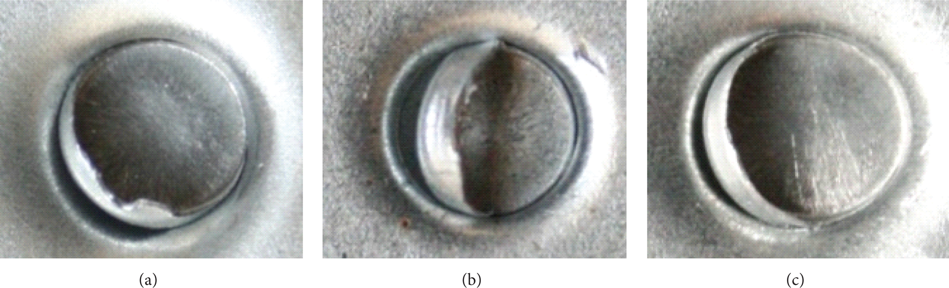
Failures of CL joints: (a) samples with H220PD materials, (b) samples with DC06 materials, and (c) samples with DX51D materials.
The destruction mechanism of CR joint overpress is different comparing to CL joint. The separation is due to material ductile failure in area “1” (Figure 11) and due to complete pulling the rivet out of the lower sheet metal. The rivet remains in the upper sheet metal.
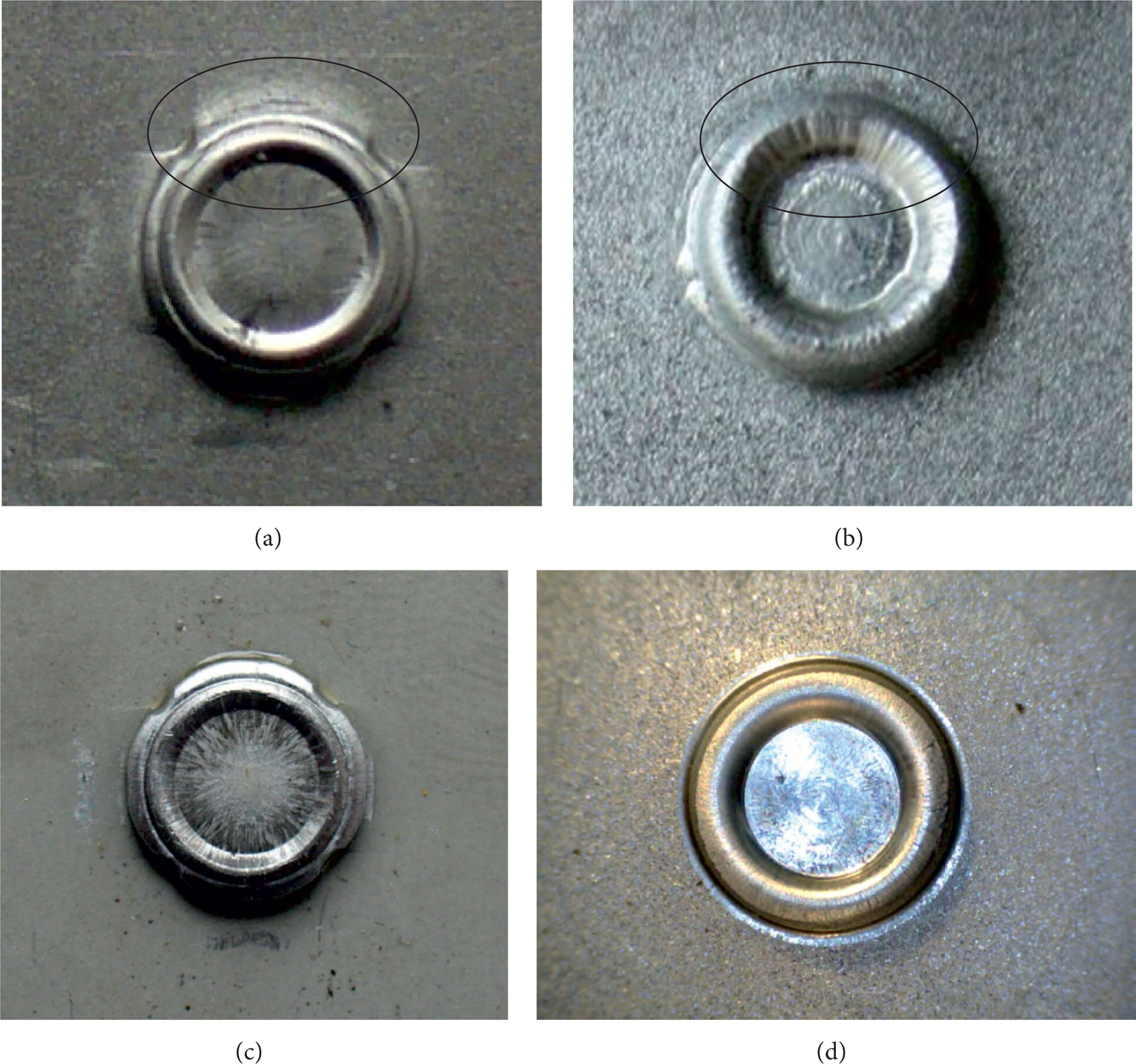
The upper sheet metal formed as a bulge by the rivet tears on its circumference (Figure 13). For H220PD, the fracture is visible in the bottom and on the circumference (Figure 13(a)). For remaining analyzed joints (made of DC06 and DX51D), the fracture occurred on the overpress circumference (Figures 13(b) and 13(c)).

Failures of CR joints: (a) samples with H220PD materials, (b) samples with DC06 materials, and (c) samples with DX51D materials (the defect is indicated by the line).
Knowing the microhardness change, it is possible to forecast fracture sensitive areas. In the mechanical processes, the stress state, grain size, and material properties determined allowable deformations [25].
The values presented in Figure 14 were achieved by measuring the microhardness in specified locations on the metallographic microsections. The starting microhardness for corresponding sheet materials was indicated in brackets.

The microhardness in cross-section points for joints (a) CL and (b) CR.
Different microhardness values were achieved both for CL and CR joints depending on the material type. The highest values were achieved for DX51D, and the lowest for DC06. This was related to mechanical properties and material's strain hardening curve. Such a microhardness arrangement was observed for both CL and CR joints. For CR joint (Figure 14(b)), the microhardness differences between materials were higher than those for joints produced with CL technology (Figure 14(a)).
For CR joint, the microhardness values in measurement points “4” and “9” are higher than values for CL joint. Similar situation occurs in points “3” and “10.” As the segmented die has moving elements, it enables more intensive plastic material flow. While the material flows, the die segments move, and the material hardens more due to a plastic strain in previously mentioned areas of joint.
Whereas in the necking area of the upper sheet material for CR joint (in points “2” and “7”) the microhardness increase is lower than that for CL joint. For CR joint, the upper and lower sheets are slightly bent by the plastically flowing material of the joint bottom, while forming with the rigid die results in significant material extension, thus significantly increasing the material hardening and material hardness itself.
An inappropriate material selection for SPR joint may result in joint fracture [26]. The rivet's state of stress, especially in very small ones, is of very high importance [27].
The initial structure of the rivet for CR technology was uniform and free of strain (Figure 3). No defects due to the rivet pressing were observed for each CR joint forming. The overpress bottom's joined material thickness reduction occurred (Figure 15). The necking occured on the side surface, in a similar way to clinching joints [2]. The largest gap between sheet metals occurred for DX51D (Figure 15(a)), and for remaining cases gaps were smaller (Figures 15(b) and 15(c)). The cylindrical surface thickness values were similar. The relevant differences were observed in the joint bottom, namely, at the deformed rivet edge.

The metallographic images of joint area: (a) DX51D, (b) DC06, and (c) H220PD.
The thicknesses of thinned upper and lower sheet DX51D were identical. Changing the material to DC06 resulted in excessive lower sheet thickness reduction, and the material continuity was maintained. While changing the sheet material to H220PD, the upper sheet metal thickness reduced and then the upper sheet fractured. This was due a different formability limit of joined materials.
For H220PD sheet material, the formability limit was achieved closely to the points. The microhardness values in points “4” and “9” (Figure 14(b)) and the sheet material continuity curve in the joint (Figure 15(c)) show that the formability limit for H220PD was achieved.
One of the highest CR joint forming forces was achieved for H220PD. For this material combination, the upper sheet metal fracture also occurred (Figure 15(c)-2). In this joint, the highest rivet's microhardness increase occurred in its lower part locking the sheet material (Figures 6(c) and 16).

The hardness change in specified rivet locations for joint made of H220PD.
The material on the top of the rivet in its axis has no contact with the tool (tapered hole in the rivet). While pressing the rivet, firstly the rivet edges are upset, and then the material starts flowing in the lateral directions to the rivet axis. The microhardness increase was the highest in point “6” of this area.
The material on the rivet edges in the lower rivet part has a limited capability of plastic flow. The rivet edge is pressed into joined sheets. The lower part of the edge is bent outwards while pressing. The microhardness in point “4” of this area is lower than the value in point “6”.
Around the external rivet's surface (points “1,” “2,” and “3”), the microhardness increase is not as high as an axial one, as a result of the initial shape. Around the external side and edge the rivet has to strain in extent that enables forming the lock without rivet fracture.
Depending on joined material arrangement, different lock forming occurs and the rivet deforms in different way (Figure 17). The lowest material lock was achieved for DX51D/RA-K 40/70 material arrangement (Figure 17(c) and Table 4). Changing the lower sheet from DX51D + Z to RA-K 40/70 (variants A and D) decreased t u by 57% and t n by 15% (Table 4). The rivet did not strain enough to deform the sheet metals. The rivet edges were upset, thus resulting in sheet metal thickness reduction in the lower part of the joint. The largest interlocking was achieved for material 5754, but both sheets material were thinned (Figure 17(d)). For sheets made of alloy 5754 parameter t u increased by 25%, and t n decreased by 34% comparing to joint made of DX51D + Z. For alloy 5754, the forming force was high, and the maximum load-carrying ability while shearing was quite low (Figure 8).
The measured neck thickness and undercut value (in mm).
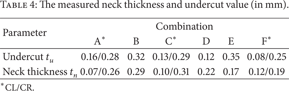
CL/CR.

CR joint cross-section for material combinations: (a) DX51D/DX51D (A), (b) DX51D/H220PD (B), (c) DX51D/RA-K 40/70, (d) 5754/5754.
While comparing CL with CR for H220PD (both sheets), significant increase in t u parameter by 212% and t n parameter by 58% was observed (Table 4). For sheet metal arrangement according to variants “A” and “C”, the increased material locking was also observed. The highest improvement was achieved for variant “F”.
All the materials studied could be joined by clinching. With a few exceptions, this result was not expected at the outset of the study. The maximum shearing load depends heavily on the type of clinching method used (CL or CR) and varies significantly. For some material type arrangements, joining with rivet (CR) resulted in joint material separation.
5. Conclusions
The experimental CR joint forming analysis allowed researching the forming force depending on the sheet material type.
Depending on the joined material type, the rivet formed the joint, for which the maximum shearing force of joint overlapping was achieved.
For tested materials, the highest force was achieved for DX51D + Z/RA-K 40/70, and the lowest one was achieved for alloy 5754. For 5754, the highest difference between the forming force and the maximum shearing force was achieved. The high force value is due to a rivet material strain demand.
Applying the rivet for joint forming increases the lock size in sheet material (t u ) for DX51D + Z by 75% comparing to CL joint. However, forming the joint in this combination requires increasing the forming force by 290%.
Changing the joining method from CL to CR for material DC 06 increased the t u value by 123%. The force increased for this sheet material layout was 280%.
The best effect of lock increase in the joint was achieved while changing the joining method for H220PD material. The t u parameter increased by 150%. Increasing the lock size in this case of CR joint forming requires increasing the forming force by 283% compared to CL joint.
Clinching joints of 5 mm diameter feature much lower maximum joint strength compared to joint with an additional rivet. For DX51D + Z and DC06, the maximum joint shearing force increase was 150%. While for H220PD, the maximum joint shearing force increase was 316%.
CR joint forming pushes the unsafe material thinning area to the joint bottom. In CL joints, the necking locates in the center of the overpress height.
While joining different sheet metals, the critical thinning may occur, thus resulting in material layer fracture. The material discontinuities lower such a joint tightness. This may result in faster inner corrosion due to external factors.
Using the rivet in joint also changes the separation method. While shearing the CL joint, some part of the upper sheet metal remains in the lower sheet material. While shearing the CR joint, whole upper sheet metal remains on the rivet. The separation itself occurs by separating the sheet metals.
Footnotes
Acknowledgment
The paper was elaborated within the project “Application of progressive tool coatings for increasing the effectiveness and productivity of forming sheets made of modern materials” (APVV-0682-11).