
Abstract
A numerical model is developed in order to find out the performance characteristics of gas foil bearings. The static performance analysis of gas foil bearings has been carried out using an elastic foundation model of the foil. The steady state results have been compared with the experimental and theoretical results available in the literature. The characteristics of the bearing have been investigated with change in foil pivot position. It has been shown that the load carrying capacity is different for different foil pivot positions. Besides effect of bearing parameters like eccentricity ratio, length to diameter ratio, compliance coefficient, and bearing number on the load carrying capacity with different foil pivot positions have been studied.
1. Introduction
The design trend of modern rotating machinery is towards higher rotating speeds and lower weight by improving the prediction of rotor dynamic behavior. Gas-lubricated bearings operate at very high temperature since chemical degradation of the lubricant does not occur. Hence high performance oil-free turbo machinery implements gas foil bearing (GFBs) to improve mechanical efficiency in compact unit. The GFBs fulfill most of the requirements of novel oil-free turbo machinery by increasing their reliability in comparison to rolling elements bearings. Foil bearings are made of one or more compliant surfaces of corrugated metal and one or more layers of top foil surfaces. The compliant surface provides structural stiffness and comes in several configurations such as bump type and leaf type. The GFBs enable high speed operation and large load capacity. In bump-type foil bearings, the top foil is supported by compliant bumps which deforms elastically under the pressure created by the hydrodynamic film. Coulomb type damping arises due to the relative motion between the bumps and the top foil and between the bumps and the bearing support wall. The gas foil bearing design constrains the direction of shaft rotation to only one direction. Due to the hydrodynamic film created by the rotor spinning, the top foil expands resulting in a larger film thickness than in a rigid bearing. Initially when the rotor starts spinning, the back of the foil is in contact with the bump foils and the outer side of the foil is in contact with the journal. As the rotor spins to a sufficiently high speed, the top foil contracts as air is dragged into a thin annular film between the foil and the shaft (Figure 1).

Schematic view of bump type GFB.
Once the shaft starts rotating, the working fluid (usually air) pushes the foil away from the shaft so that there is no more contact. The shaft and foil are separated by the high pressure which is generated by the rotation of shaft which pulls gas into the bearing. So it becomes important to find out the pressure distribution within the shaft and the foil. The behaviour of fluid within the bearing has been expressed by Reynolds equation. In each technical publication, focus is concentrated to solve Reynolds equation. Solution of the Reynolds equation (Mazumdar [1] and Walowit and Anno [2]) enables to determine the pressure distribution in a bearing. While the journal is rotating inside the bearing, journal surface rubs over the bearing surface due to the fluctuation of speed and the load variation. Thus the frictional forces are developed and the magnitudes of forces depend on the mechanism of deformation of the corrugated foil strips (Ku and Heshmat [3]) used in compliant surface foil bearing. Moreover, the development of various classes of bending-dominated foil bearings has taken an aggressive path towards improving bearing speed and load capability (Heshmat [4]). Peng and Carpino [5] have attempted to develop an accurate and effective method to calculate both the stiffness and damping coefficients of gas foil bearings in order to improve operating characteristics, that is, load carrying capacity, speed, and maximum temperature level.
Further the performance of a gas foil bearing has been evaluated using a spring supported compliant foil as the bearing surface (Heshmat et al. [6]). In this model, the elastic displacement of the foil is proportional to the local pressure difference. Lee et al. [7] have proved that the damping capacity of gas foil bearings can be enhanced by using a viscoelastic top foil material. For the improvement of numerical analysis, finite element (FE) top foil model has been developed by San Andrés and Kim [8] in order to calculate the deformations in top foil and bump strips. Further, the same authors [9] have used an axially averaged pressure, coupling the pressure field to the structural deflection, thus enabling a journal to move beyond the nominal bearing clearance when subjected to large loads. Lee et al. [10] have described a finite element foil structural model that takes into consideration the three-dimensional foil shape. Lee et al. [11] focused on operating characteristics of the bump foil journal bearings with top foil bending phenomenon and correlation among bump foils. The top foil deflection differences between the areas touched with and without bump foil. Lee et al. [11] showed that the top foil deflecting appearance should be taken into consideration for more reliable estimation of the bump foil bearing behavior. A report by Iordanoff [12] has shown that a simple 2D model enables the optimum profile for a noncompliant thrust bearing sector. This profile is a composite profile, that is, one in which the leading portion has a constant slope followed by a surface parallel to the runner. The top foil follows the bump foil in its deformation, has node flection between two bumps, and does not interact with the bump deflection. Thus the deflection is supposed to be only dependent on the bump foil.
In gas foil bearings, the bump interactions must be taken into account to correctly describe the structural behavior (Lez et al. [13]). It allows the determination of the dynamic friction forces at the top and at the bottom of the bumps by simple integration of ordinary differential equations. To reduce friction and minimize wear during sliding, which occurs at startup and shutdown, DellaCorte et al. [14] have introduced a systems approach in which the solid lubrication is provided by a combination of self-lubricating shaft coatings coupled with various wear resistant and lubricating foil coatings. Xiong et al. [15] have aimed at the development of aerodynamic foil journal bearings applying to a small high speed cryogenic turboexpander. Foil stiffness has been increased by constructing number of copper wires fixed behind the foil which results in high stability. Hou et al. [16] have proposed the same construction of the foil for a small cryogenic turboexpander used in Brayton cycle. In this paper the only difference is that the copper wires are replaced by a whole rectangular elastic material and the foil element is wrapped around the journal only on the circumference in order to avoid the flaw that the stiffness of foil element is not equal. The wear on the foil and the journal increases, during starts or stops, due to the relatively heavy rotor weight as compared with size of the bearing. To minimize the wear problem during the starts or stops, Kim and Lee [17] have introduced the hybrid air foil bearing which combines hydrodynamic pressure with hydrostatic lift. The static stiffness has been measured to estimate the load capacity of hydrostatic operation when rotor is stationary. The gas foil bearings with bump strip compliant layers can sustain large loads and provide damping to reduce shaft vibration. However, in the high temperature applications, the thermal effects can considerably affect the performance of the GFB structure due to the change in operating clearances and material properties. Thus to study the thermal effects, Kim et al. [18] have estimated the structural stiffness of the GFB for increasing shaft temperatures. Howard [19] has investigated the degree of misalignment that the rotor bearing system can tolerate. The limits on misalignment dictate how precisely housing must be manufactured and how much thermal distortion can be tolerated. During the investigation it has been found that the GFBs, with higher minimum film thickness, have the ability to handle high degrees of misalignment relative to other bearing types, thus making them easier to integrate into high speed and high temperature applications.
It has been observed that in all the studies the foil pivot has been considered at the top of the bearing. However, when different studies were carried out to characterize GFBs, there is no information regarding the effect of different foil pivot positions. In view of this, an attempt has been made to investigate the effect of different foil pivot positions on the load carrying capacity with different aspect ratio, eccentricity ratio, compliance coefficient, and bearing number.
2. Theory
2.1. Governing Equations
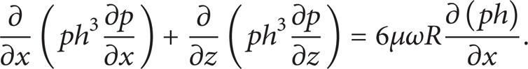
The governing differential equation of gas-lubricated bearings is nothing but the generalized Reynolds equation [1], given as

where (x, z) are the circumferential and axial coordinates on the plane of bearing as shown in Figure 1. The pressure takes ambient value (p a ) on the side boundaries of the bearing. For steady state conditions the time dependent term in (1) is zero. Hence the generalized Reynolds equation for an isothermal, isoviscous ideal gas is
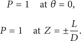
The boundary conditions for the solution of (2) are

The first boundary condition recognizes that the gas enters and leaves the clearance space at ambient pressure. The leading edge of the foil is fixed to the bearing housing, while the trailing edge is free to deflect.
The variation of the film thickness, h, is due to the eccentricity (e) and the deflection of the foil (w t ) under the imposed hydrodynamic pressures developed between the bearing clearance and it is given by [10],
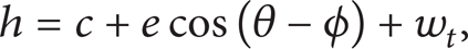
where w t is the elastic deformation of the foil structure under the imposed hydrodynamic pressure. This deformation (w t ) [8] depends on the bump compliance (α) and the average pressure across the bearing width (Figure 2),

where

Single segment of bump foil [8].
The compliance (α) (the deflection of foil structure per unit load acting per unit area on the foil structure) [6] is given by

The variables in the governing equations (2) and (4) can be normalized by using the following substitutions as follows:

The nondimensional Reynolds equation as given in (8) is obtained by substitution of the above,

where

Similarly, the nondimensional film thickness is given as

where

Now boundary conditions will be
2.2. Solution Scheme
The nondimensional Reynolds equation (8) has been discretised using finite difference scheme resulting in a nonlinear algebraic equation as shown in (13). Newton-Raphson method has been used to estimate the pressure distribution satisfying the boundary conditions:
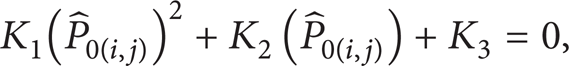
where

2.3. Steady State Formulation of Reynolds Equation
The force of the gas film acting on the journal can be computed by integrating the pressure over the bearing surface. According to the coordinate system illustrated in Figure 3, this integration can be written as

For numerical integration, Simpson's one-third rule has been used. Finally the total nondimensional load is given by

In the present algorithm, a fixed coordinate system has been considered (X and Y). Therefore, for steady state equilibrium, the horizontal load component should become zero. For a given eccentricity ratio, the attitude angle is varied till the horizontal load component approximately becomes zero. Bisection method has been used for bracketing and also to calculate the correct attitude angle. The load capacity is simply equal to the vertical load component.

The coordinate system and the sign convention of the journal forces.
Initially, the nondimensional top foil deflection (W) is assumed as zero. To start with the iteration method, the nondimensional pressures at all the mesh points are assumed as 1 (i.e., ambient pressure) and those at the boundaries are set to the ambient pressure. The quadratic equations have been solved by using Newton-Raphson method for all the mesh points to estimate the pressure distribution. Then the nondimensional top foil deflection (W) is found out. After that, by substituting the new value of nondimensional top foil deflection (W) in the equation of film thickness, once again the quadratic equation is solved for all the mesh points to correct the pressure distribution. The iterative process is carried out until the following convergence criterion is satisfied:
3. Results and Discussions
3.1. Validation
The validity of the present analysis and computational program is assessed by comparison of predictions with published data available in open literature as shown in Tables 1 and 2. A bearing reduces to ordinary gas bearing for compliance coefficient S = 0. From the comparison, it has been observed that the present results are fairly matching with those from references.
Steady state characteristics for L/D = 1, Λ = 1.0, and S = 0.

Peng and Carpino [5].
Heshmat et al. [6].
Steady state characteristics for L/D = 1, Λ = 1.0, and S = 1.

Peng and Carpino [5].
Heshmat et al. [6].
3.2. Analysis of Different Foil Configurations
The steady state performance characteristics of gas foil bearing have been estimated by using the solution scheme described in the previous section. In this section, results are generated by changing pivot position of foil structure along the circumferential direction of the bearing as shown in Figure 4. The main aim of this analysis is to find out the effect of various bearing parameters on the load carrying capacity for different foil pivot positions at θ = 0°, 18°, 36°, 54°, 72°, and 90°. In order to obtain different foil pivot positions, the following boundary conditions are used to solve the above nondimensional Reynolds equation (8) and the nondimensional film thickness equation (10).

Schematic diagram of different foil pivot positions.
For each foil pivot positions at θ = 0°, 18°, 36°, 54°, 72°, and 90°,

3.2.1. Pressure Profile for Different Foil Pivot Positions
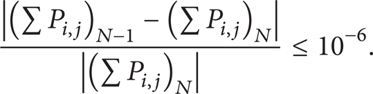
Figure 5 shows the pressure profile for different foil positions along the circumferential direction of the gas foil bearing at mid-section of the bearing and Figure 6 shows corresponding foil deflection profiles. It has been observed from the pressure profiles in Figure 5 that as the angle of the pivot foil position increases, the maximum pressure created in the bearing decreases. The pressure reduction has been occurred from θ = 0 to 180°. Figure 7 displays the surface profiles of the nondimensional pressure.

Pressure profile for different foil pivot positions (Λ = 1, S = 1, and ε = 0.4).
Nondimensional foil deflection profile for different foil pivot position (Λ = 1, S = 1, and ε = 0.4).

Surface profile of nondimensionalised pressure.
3.2.2. Film Thickness Profile for Different Foil Pivot Position
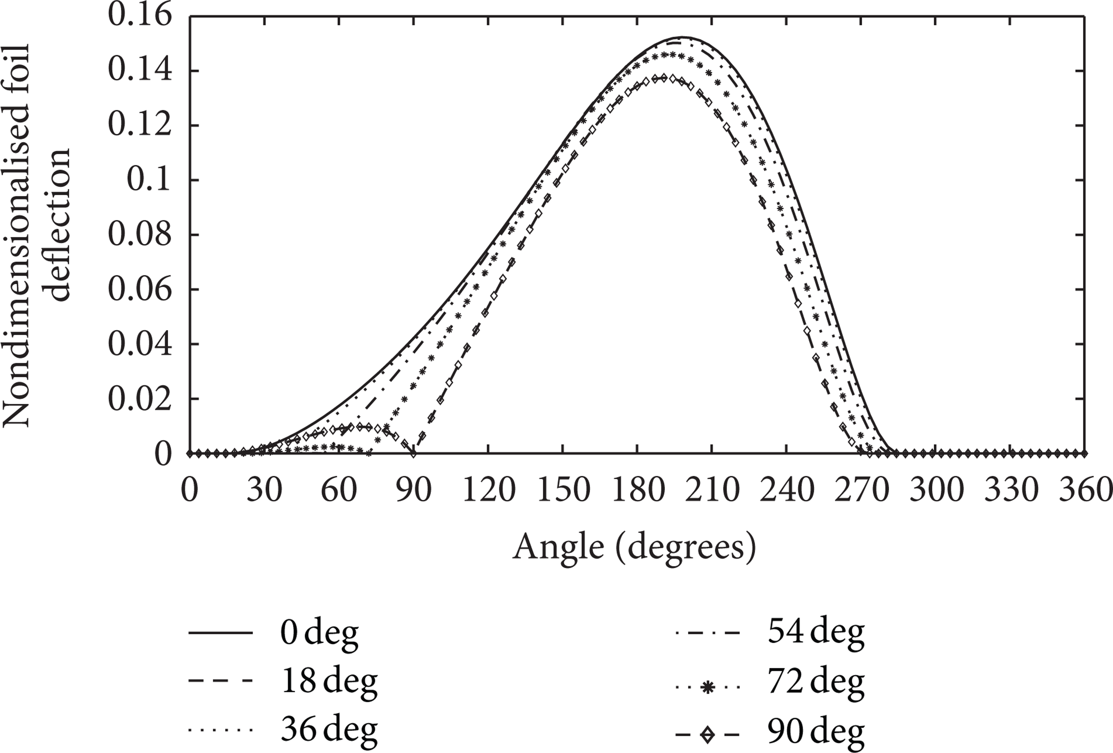
Figure 8 shows the film thickness profile for different foil positions along the circumferential direction of the gas foil bearing. Observing the film thickness profile, it has been noted that the film thickness is continuously decreasing from θ = 0 to 120° and goes on increasing as the angle is further increased. The minimum film thickness is occurred at the section where the maximum pressure is observed.
Film thickness profile for different foil pivot position (Λ = 1, S = 1, and ε = 0.4).
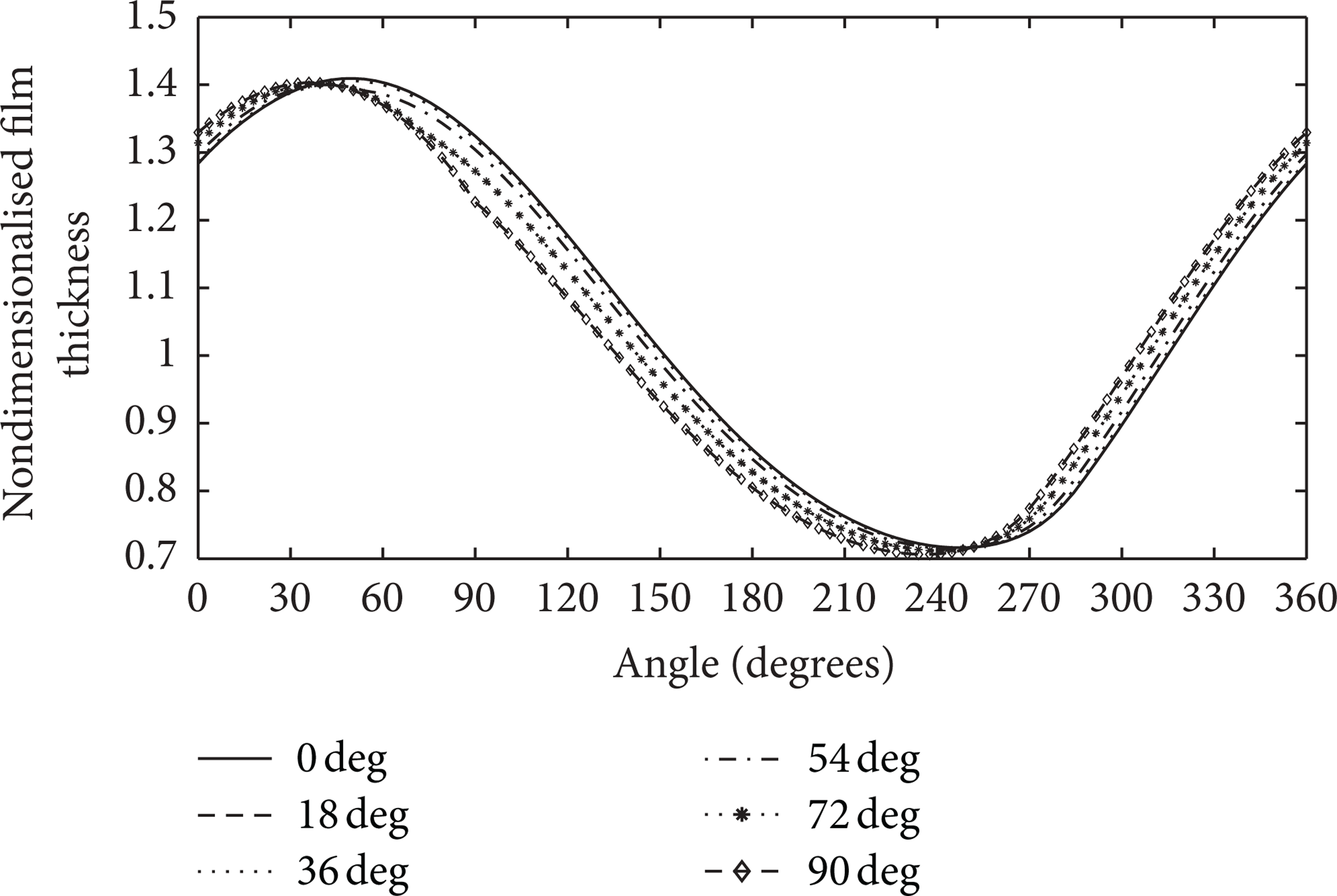
3.2.3. Nondimensional Load Profile for Different Foil Position
Figure 9 shows the nondimensional load profile for different foil positions along the circumferential direction of the gas foil bearing. Analyzing the nondimensional load profile, it should be pointed that as the angle of the pivot foil position increases, the load capacity of the bearing decreases.

Nondimensional load profile for different foil position (Λ = 1 and S = 1).
3.3. Effect of Various Bearing Parameters on the Static Performance of Gas Foil Bearings
The results are obtained for the steady state analysis of GFB with eccentricity ratio varying from 0.1 to 0.8 for different values of
Effect of length to diameter ratio
3.3.1. Effect of Eccentricity
As the eccentricity ratio increases from 0.1 to 0.8, nondimensional load capacity increases and nondimensional minimum film thickness decreases. Due to the decreased film thickness, air gets compressed at the minimum film thickness section. Thus the pressure at that section increases, thereby increasing load capacity of the system. It has been observed from Figure 9 to Figure 18 that the trend in each case is the same. It means that, for each foil pivot position, the load capacity increases as the eccentricity ratio increases.
3.3.2. Effect of Length to Diameter Ratio
Observing Figures 10, 13, and 16 it is found that, as the length to radius ratio decreases, nondimensional load capacity decreases for the same eccentricity ratio. The length to radius ratio is proportional to the size of the bearing. As the size decreases, the total load capacity of the system also decreases.
3.3.3. Effect of Compliance Coefficient
Examining Figures 11, 14, and 17, it is observed that increasing compliance coefficient reduces nondimensional load capacity. Compliance of bearing is the deflection of the foil structure per unit load acting per unit area of the foil structure. Increased compliance decreases the deflection of the foil.

Effect of compliance coefficient on
3.3.4. Effect of Bearing Number
Analyzing Figures 12, 15, and 18, it is noted that when the bearing number is increased, nondimensional load capacity also increases. The bearing number is a nondimensional parameter which indicates performance characteristics and geometrical characteristics of bearings. For given performance characteristics, bearing number varies with geometrical characteristics and vice versa.

Effect of bearing number on
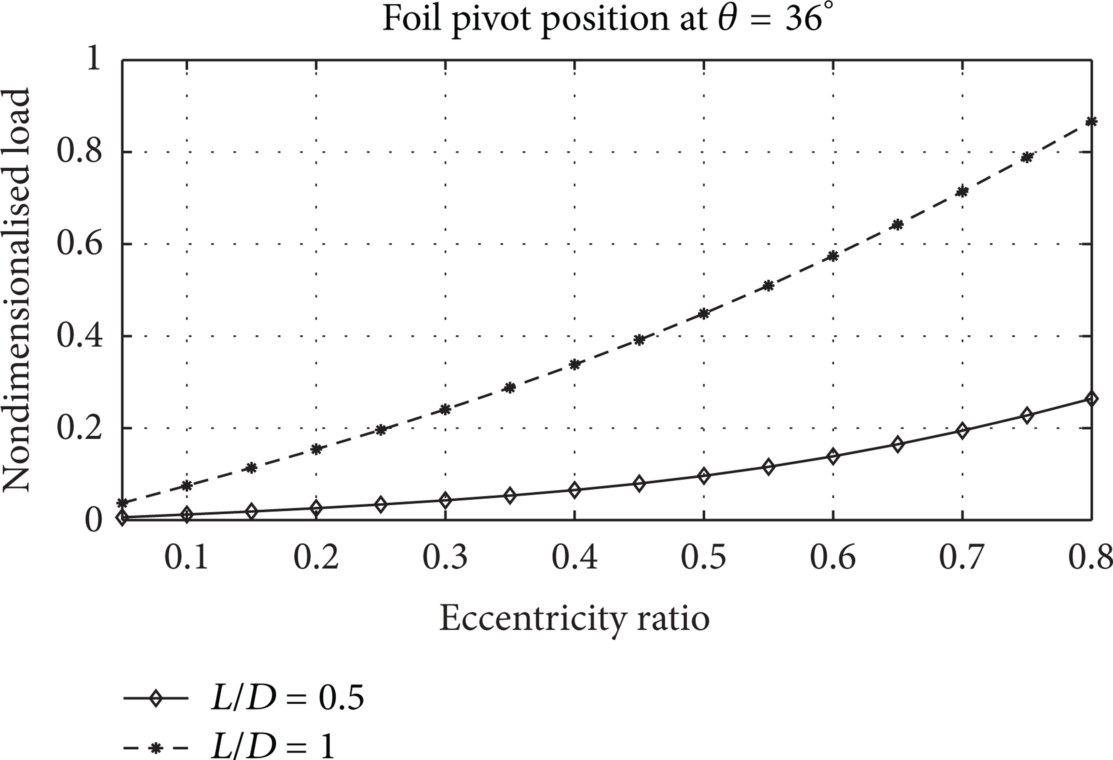
Effect of length to diameter ratio

Effect of compliance coefficient on
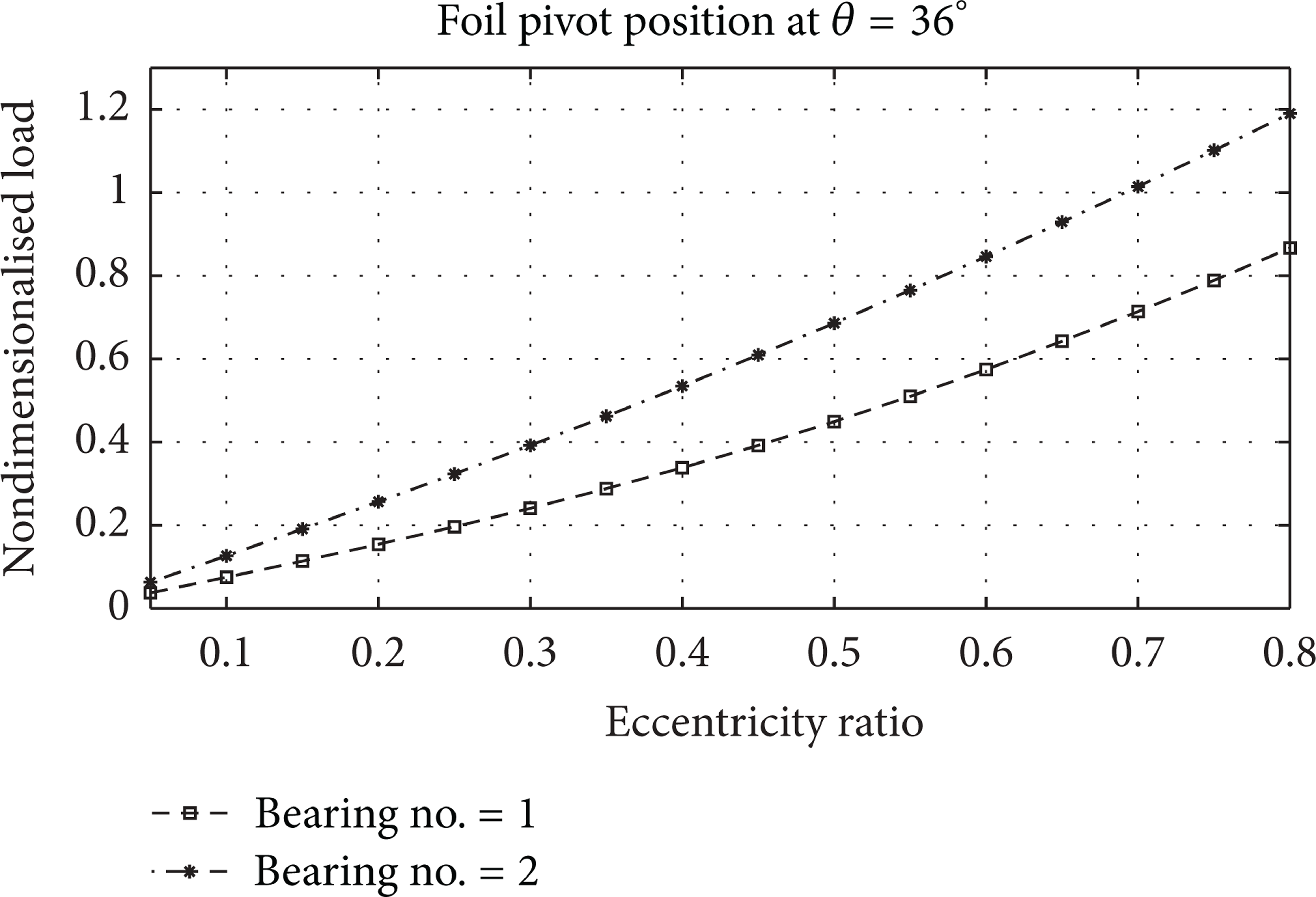
Effect of bearing number on

Effect of length to diameter ratio

Effect of compliance coefficient on
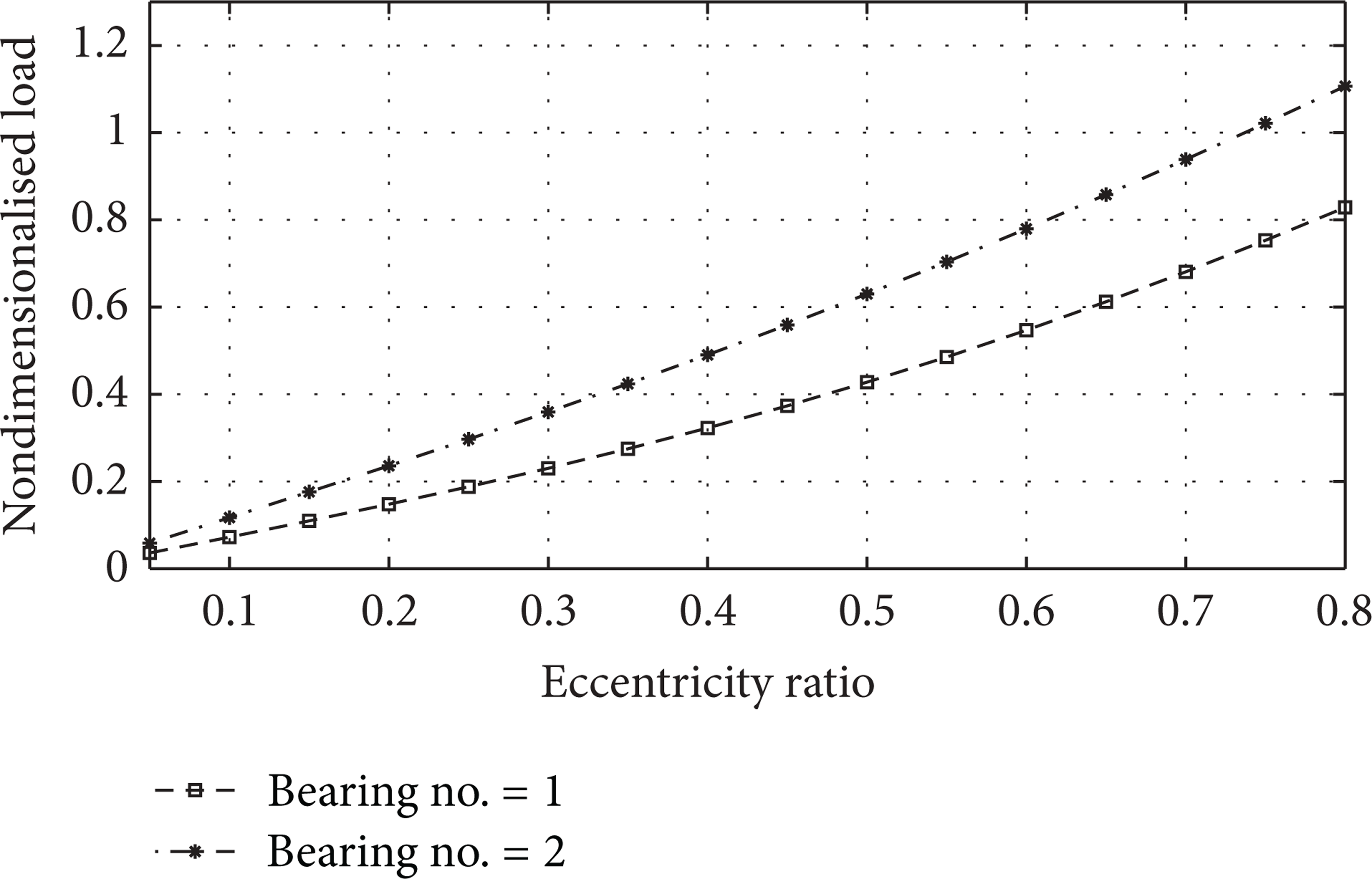
Effect of bearing number on
3.3.5. Effect of Foil Pivot Position
An analysis of gas foil bearing has been carried out in this section to observe the effect of foil pivot position. As the compliance coefficient increases, the load capacity of gas foil bearing decreases. This is due to the fact that the flexible foil deflects sufficiently to maintain high film thickness even at large eccentricities. Thus from a design point of view, it may be advisable to use high compliance bearings at low loads. High loads, however, can be supported only with the bearings of low value of the compliance coefficient.
By changing foil pivot position, bearings can be designed for different load capacities. As the pressure develops within the bearing sleeve and the journal decreases with increased pivot angle, consequently the load capacity of the bearing also decreases. On the other hand, the load capacity may be increased by reducing the value of the compliance coefficient.
It may be assumed that the journal surface is covered with fluid moving with certain velocity. The journal surface is inclined at a certain angle to the housing surface. As the journal surface moves it drags the fluid along it into the converging wedge. Due to the hydrodynamic action, a pressure field is generated as there would be more fluid entering the wedge than leaving it. The generated pressure separates the two surfaces and is also able to support a certain load. The bearing number is directly proportional to the angular speed of the journal. As the speed of the journal increases, the magnitude of the bearing number also increases. With higher bearing number (i.e., higher journal speed), more fluid is dragged which results in higher pressure generation and enables the bearing to support higher load capacity. Thus, increased bearing number increases the load capacity of the bearing.
It has been seen that once the fluid enters the diverging section of the bearing, the subambient pressure starts to generate. This is due to the fact that as the fluid enters the diverging section, the fluid flowing from the smaller section is not able to follow the abrupt change of the boundary. Thus, the fluid flow separates from the boundary and turbulent eddies are formed which results in the formation of vapor bubbles of a flowing fluid. This phenomenon is responsible for negative pressure generation. Thus the pressure difference is created on both sides of the top foil and to equalize the pressure the foil gets lifted off and aligns itself parallel to the shaft. The foil does not support any load without contact with the elastic foundation.
4. Conclusion
The steady state performance characteristics of gas foil bearing have been studied by changing pivot position of foil structure along the circumferential direction of the bearing. Pivot positions are changed at an interval of 18° ranging from 0° to 90°. The effects of eccentricity ratio, length to diameter ratio (aspect ratio), compliance coefficient and bearing number have been investigated and important results are presented. From the analysis, the following observations are made.
With the increase in eccentricity ratio, nondimensional load capacity also increases; however, nondimensional minimum film thickness decreases.
With the increase in aspect ratio (length to diameter) ratio, nondimensional load capacity also increases for the same eccentricity ratio.
Increasing compliance coefficient reduces nondimensional load capacity.
When the bearing number is increased, nondimensional load capacity is also increased.
Change in pivot position from vertical results in reduction in load capacity. Nevertheless for better load capacity, vertical pivot position is recommended.
Other performance characteristics like flow, friction, and so forth may be studied with different pivot positions.