
Abstract
Considering the grinding geometry of the thread grinding dynamic contact arc length, a dynamic numerical thread grinding model has been set up on the basis of study of a single grit grinding model. The properties of grinding force and dynamic contact arc-length have been studied by means of the developed numerical model. The results have shown that the angle of helix has little effect on the dynamic contact arc-length than the wheel speed on the dynamic contact arc-length. And the wheel speed also produced a large effect on grinding force.
1. Introduction
Grinding is one of the main methods of precision manufacturing and the process quality depends to a large extent on the experience of the operator. The grinding force comes from the elastic deformation, the plastic deformation, and the grinding swarf from the contact surface of the wheel and the workpiece. Meanwhile, the friction among the grinding grits, bond, and workpiece can also contribute to the grinding force [1]. Among these factors, the workpiece elastic deformation is one of the key influence factors of processing precision for high precision machining. The main challenge in designing ultraprecise grinding machine is developing the accurate grinding force models [2, 3]. In the recent years a number of researchers throughout the world have developed some grinding force models and calculated the formula for different kinds of workpieces. For example, as for the cylindrical grinding, some researchers set up the cylindrical traverse grinding force model on the basis of the analysis principle of the status of a single grinding grit. And some researchers analyzed grinding force by using the stress concentration theory and the mathematical statistics theory [4, 5]. Some studies have been conducted to investigate the grinding theory, analyze the friction force, plow friction, and cutting force in the surface grinding process, and discuss the effect of parameters on the properties of grinding force by analyzing the numerical number [6, 7]. On the other hand, Liu et al. addressed an empirical model of the grinding force in the study of multivariables in the grinding process [8]. With regard to the grinding force model, researchers presented some analytical results about the workpiece elastic deformation caused by grinding force [9–11]. However little research has been conducted for the thread grinding process. In this paper a numerical thread grinding model will be developed on the basis of the single grinding grit model. The thread grinding dynamic contact arc is analyzed in the viewpoint of the grinding geometry.
2. Mathematical Model
2.1. Arc Length of Contact between the Wheel and the Workpiece
There is an angle between the wheel axis and the workpiece axis for the thread grinding, which is different from the normal cylindrical grindings. It is necessary that the effective equivalent wheel diameter d e must be given between the finished surface and the projection plane of the wheel circumferential speed in grinding zone:

as shown in Figure 1.

Thread grinding sketch map.
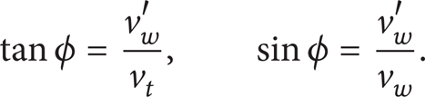
In the thread grinding process, the angle between the wheel axis and the workpiece axis is defined as Ψ and the thread helical angle is φ. Certainly Ψ = 90° – φ. For the grinding wheel, the relationships of the workpiece circumferential speed along the helix v w ′ and axial velocity v t are given as follows:
The arc length of contact surface between the wheel and the workpiece is one of the important parameters in grinding process, which produces a significant effect on the grinding force. The analysis of grinding path is the premise of modeling grinding force. The grinding path is shown in Figure 2.

The grinding path in the grinding process.
As shown in Figure 2, the active cutting point on the workpiece moves from F′ along the curve path to A′ in the inverse mill. For the workpiece, the grinding path F′B′C′A′ is a cycloid curve synthesized by the grinding wheel speed v s and the workpiece speed v w . The cycloid curve can be expressed in the following equations in the radial direction and tangential direction:
radial direction:

tangential direction:

where v s is the grinding wheel speed, v w is the workpiece speed, θ′ is the turning angle of the wheel, and d s is the diameter of the wheel. The total length of grinding path can be obtained through the grinding path equation:

Hence the kinematic contact arc length is obtained,

where d e is the effective equivalent wheel diameter and a is vertically cutting depth.
2.2. Grinding Force Model
As the single grinding grit is the basis of the analysis of the grinding force in the grinding process, the stress to a single grit should be studied first, as shown in Figure 3. The single grit grinding force formula is given:


Stress on grinding grit.
The grit has a tip angle because it is the circular cone. The center line points to the wheel radius and the generatrix length is ρ. Hence the contact area is
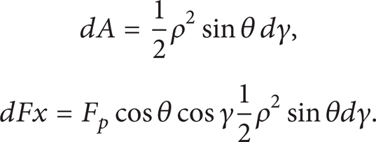
Since
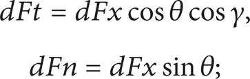
therefore, the grinding force on the total grit can be deduced from formulas (8) and (9):

where F
p
is the grinding force per unit N, θ is the half tip angle of grit (the half tip angle is changed from 40° to 72.5° in the engineering applications), and
From the kinematic contact length the number of effective kinematic grit N d is
where N t is the number of unit effective static grit on the wheel surface and b is the grinding width.
Then the grinding force model is obtained:

According to formulas (6) and (9), the thread grinding force can be calculated by the following equations:


2.3. Model of Workpiece Elastic Deformation
The workpiece can be fixed by the two core clampers in front and back surfaces, which forms an elastic system, as shown in Figure 4. When the grinding wheel moves along the workpiece, the workpiece elastic deformation in the normal direction will be caused by the normal grinding force. It produces a large effect on the workpiece processing precision.

Workpiece grinding by the two core clampers in front and back surfaces.
The curvature equation caused by F n is

where m is the distance between the grinding wheel and the front core clamper, n is the distance between the grinding wheel and the back core clamper, y is the elastic deformation, E is the elastic modulus, and I is the moment of inertia.
The elastic deformation y can be obtained by integrating (15) twice:

where A1, A2, B1, and B2 are the integration constants.
The four integration constants can be determined by the following conditions.
The deformations of a and b interfaces are equal.
Deformation in the core clamper is zero.
So the four integration constants are

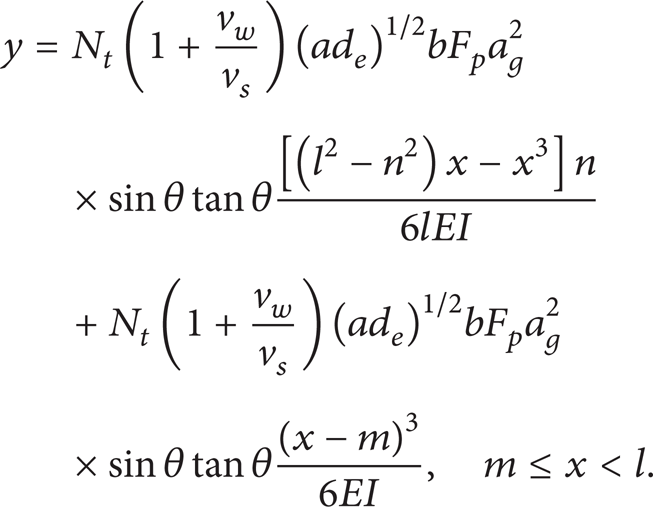
Substituting (17) and (14) in (16), the elastic deformation can be obtained:
3. Calculation and Analysis of Grinding Force Model in the Thread Grinding Process
In the case of thethread grinding force study, the working target is ball screw and the grinding wheel is vitrified bonded grinding wheel. The grinding parameters are given as v s = 25–35 m/s, v w = 6–10 m/min, a = 20–25 μm, b = 6 mm, l = 5 m, ds = 500 mm, and dw = 28 mm and the half tip angle of grit is θ = 40°–72.5°.
3.1. Effect of the Helical Angle on Kinematic Contact Arc Length
As shown in Figure 5, the kinematic contact arc length is becoming longer as the helical angle increases with the case of the constant grinding wheel speed. Meanwhile, the kinematic contact arc length is getting shorter with the increase of the grinding wheel speed while keeping the helical angle constant.
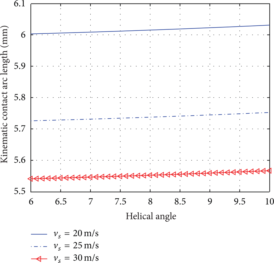
The change of kinematic contact arc length.
3.2. Effect of the Half Tip Angle on the Grinding Force
The variations of the grinding force along with the half tip angle have been analyzed and presented in Figure 6. It can be seen from Figure 6 that both the radial grinding force and the tangential grinding force are reduced with the rise of the half tip angle, while the grinding wheel speed remains constant. The forces get larger when the grinding wheel speed is getting smaller, as shown in Figure 6.

The variations of the radial and tangential grinding force.
If the grinding wheel speed is constant and the workpiece speed is variable, the radial grinding force and the tangential grinding force are getting smaller with the increase of the half tip angle. If the workpiece speed is constant, the radial grinding force and the tangential grinding force are getting smaller with the increase of the half tip angle. If the half tip angle is constant, the radial grinding force and the tangential grinding force are getting larger with the increase of the workpiece speed, as shown in Figure 7.

The variations of radial and tangential grinding force.
The elastic deformation is solved in the condition that the grinding wheel is 1 meter from the front core clamper and 4 meters from the back core clamper. It is shown in Figure 8 that the elastic deformation is affected by many factors like the wheel speed, workpiece speed, and the wheel location. So the adaptive control algorithm must be figured out to compensate the deformation error.

Deformation of different speed of grinding wheel and workpiece speed.
4. Conclusions
The kinematic contact arc length has been analyzed in the thread grinding process by means of the grinding geometry in this paper. The single grit grinding force model has been developed to further obtain the total grinding force model. Thread kinematic contact arc length and thread grinding force are analyzed and calculated on the basis of numerical analysis method. The effect of the grinding wheel speed on thread kinematic contact arc length is significant. The formula of the elastic deformation in the process is given. It can provide some guidance on the thread processing control algorithm. Future experimental work should be conducted to further verify the developed models in this paper.