
Abstract
The five-link parallel mechanism is proposed to improve joint bionic performance, and the kinematics is established for the closed chain joint actuated by two antagonistic artificial pneumatic muscles (PMs). Interference and singularity constraints are analyzed, and the joint torque model is given based on the spring-damp dynamics. Through extracting the spring force term from torque equations, the compliance of bionic joint is derived and expressed as the ratio of angle to spring torque. Energy consumption is analyzed using the PM length varying. Based on MATLAB/SimMechanics, the relationships between the axil installation parameters and swing performances are illustrated through the simulations, including the effect of the installation height and width varying on the angle scope, swing response, compliance, and energy consumption. The bionic shoulder and elbow joints are optimally designed. Compared to the conventional joints, the swing angular range of the proposed joints is enhanced, and the contraction amount of PMs is reduced. The optimal mechanism is more humanoid.
1. Introduction
The bionic joint is one of the keys of the manipulator developed to help labor working in the unstructured environment. Lightweight, anthropopathy swing trajectory, and compliance are the main performance indices for bionic design. High flexibility of the artificial pneumatic muscle (PM) actuators can make manipulator joints more anthropopathy [1–4].
A pair of antagonistic parallel installation PMs is necessary for actuating joint due to the PM only outputting unidirectional force like cable-driven system [5]. Sekine designed a PM driven parallel link mechanism to get the 2-DOF (degree of freedom) shoulder, in which stability is bad and computing and control are complicated [6]. One DOF PM driven joint is practical currently.
By far, the PM joint mechanisms swing in a plane can be mainly classified into three models, PMs connected with the rotating axis (a) through a pulley; (b) by public hinge; (c) by multilink. About the model (a), Sui [7] designed a bionic elbow joint and Chang [8] designed a 2-DOF rehabilitation robot arm and the self-organizing fuzzy sliding mode controller for this arm. Shin et al. [9] designed the variable radius pulley to improve the output torque. Obviously, the elbow designed using the model (a) is not very bionic, due to the human joint swing around the noncircle condyle. About the model (b), Hosoda et al. [10] designed a bipedal robot that can walk, run, and jump. About the model (c), Choi et al. [11] designed a 2-DOF bionic arm. Mechanism parameters are very important to the maximum swing angle, flexibility, and controlling accuracy of joint [12]. The output torque of model (a) joint is the most [13]. Both the output torque and the swing angle of the model (b) joint are the smallest. The swing angle of the model (c) joint is the biggest [14]. The model (c) joint is the most close to the skeletal muscle structure of the human joint, so it is the research hotspot. However, there are some drawbacks of the model (c) joint as below. The model (c) mechanism is symmetrical, while the human body bone is asymmetrical. The model (c) can be equivalent to the four-link mechanism; namely, connecting rod shaft is located in the connecting line between PMs' spindles.
Most of the literatures about stiffness or compliance of the bionic joints focuses on the control scheme [14, 15], and few is about how mechanism parameters affect the compliance or stiffness. Meanwhile, the stiffness of cable-driven parallel mechanism is not totally credible by traditional theoretical analysis, so the experimental analysis method is adopted [16].
The literature shows that some of bionic indices are conflicting and required to be simultaneously optimized. General analytical solution is nonexistent. The multiobjective optimization schemes under constrains are proposed to obtain an optimal bionic joint, such as evolutionary algorithms, neural network, and self-adaptive greedy scheduling [17]. However, these exiting numeric optimal schemes just give the general results, and cannot illustrate the effect of processing given parameter on bionic performance.
This paper firstly makes the rotating axis nonlocated in the line between PMs' spindles, so the bionic joint can be equivalent to the five-link parallel mechanism with more optimization space. And a simulation platform is developed in order to avoid the complicated analytic solutions of multiparameter mechanism optimum. The main contribution of this paper is proposing a novel five-link joint mechanism and using the axis installation height and width to improve the bionic characteristics including swing trajectory, compliance, and energy consumption one by one.
The rest of this paper is organized as follows. Firstly, the mechanism model and kinematics of the five-link bionic joint actuated by two PMs are established. The velocity kinematics between the swing angle and contraction of PMs is deduced. And then four swing constrains about mechanism are given. Secondly, based on the single PM dynamics model, the compliance of the bionic joint is derived. Thirdly, the simulation platform is set up using SimMechanics. The joint bionic swing performance, such as angle scope, joint compliance, energy costing, and rotation velocity, is analyzed under different mechanism parameters in details. The relationships between parameters and bionic swing are discussed in detail. Fourthly, according to the human arm joints parameters, the optimal design for shoulder and elbow joint are accomplished. The full paper is summarized and the conclusions are drawn in the last section.
2. Kinematics and Constrains
2.1. Mechanism Configuration and Kinematics
The mechanisms with one DOF and coordinate system are shown in Figure 1 swing within the x-y plane. Figures 1 (a) and 1 (b) show the initialization and swing states under h > 0 and h < 0 configuration, respectively. The proposed mechanism can be equivalent to the closed chain five-link (OA-AD-DC-CB-BO, common four-link is AD-DC-CB-BA) with two parallel PM actuators. The joint rotates towards the contraction PM side, meanwhile the antagonistic PM extents.

Bionic joint mechanism and coordinate system: (a) h > 0; (b) h < 0.
In Figure 1, M denotes the load, OE the arm bone (rigid and fixed with DC), AD the left PM (such as triceps), and BC the right side PM (such as biceps). r l and r r are the distance between the PMs installed point A, B and the joint rotation point O. L is the initial installed length of PMs. θ is the swing angle of the joint and the positive direction is in the counter-clockwise. h is the rotation shaft installed height and positive above line AB. Noteworthy, for the common four-link joint, h is 0 and r l equal to r r .
We use ∑ xoy to denote the fixed base Cartesian coordinate system and ∑ x m o m y m the floating coordinate system. According to the robotics kinematics, the rotation matrix between ∑ xoy and ∑ x m o m y m is

Without loss of generality, set the forward swinging as an anticlockwise direction. Using (1), the PM length varying value (relative to the initial installed length) can be derived as
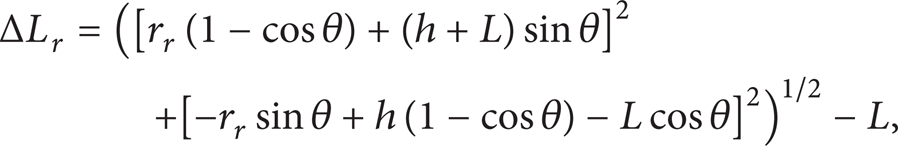

where ΔL r , ΔL l are the contraction of the right and left PM, respectively.
In the literature, regardless of mechanism models, for reducing computation complexity, the relationship of the swing angle and the PM length varying is always simply defined as


where r = r
l
= r
r
is the simplified rotating radius of the joint and
Equation (2) is more precise than (3) but more complicated. Differentiating (2), we can get the angular velocity as

Equations (2) and (4) show that the mechanism parameters, r l , r r , and h, have the distinct effect on the joint swing.
2.2. Constraints Analysis
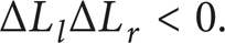
The first constraint condition (denoted by C1) is about the antagonistic installation. In the process of swing, one PM should be shortened while the other elongated relative to the PM initial installed length. Due to the antagonistic installation, two PMs length varying must meet
The second constraint condition (denoted by C2) is about the mechanism interference. Link OE cannot swing over point B or A, so

Similarly, AD or BC cannot swing over point O, so

The third constraint condition (denoted by C3) is about the maximum shrinkage and stretch constraint of PMs

where s i is the precontraction rate in initial installation state and s max the realizable maximum shrinkage rate. L r 0 and L l 0 are the length of right and left PM under s i = 0, respectively, and s a the maximum prestretch rate.
The fourth constraint condition (denoted by C4) is about kinematics singularity point. When point C moves to line OB prolongation or point D to line OA prolongation, respectively, ΔL r and ΔL l will reach the extreme value, and then

The singular point will bring the stick lock or velocity change suddenly, so it should be avoided.
Define θ ci a , θ ci c as the maximum reachable angle under the constraint Ci in the anticlockwise and clockwise swing, respectively. If θ ci a < θ cj a , the constraint Ci is stronger than Cj (i, j = 1,2, 3,4). The effective swing angle range of the bionic joint should meet all four constraints; thus

Above four constrains make the joint mechanism design more complex.
3. Compliance and Energy Efficiency Analysis
3.1. Dynamics of Pneumatic Muscle
Based on the work principle of the PM, the outputting force depends upon the inside pressure P. According to the spring-damp system dynamics [19], dynamics model of a single PM hanging a mass vertically is

in which

where m denotes the load mass (the mass of adjacent bionic joint and arm, ignoring the mass of current bionic joint and arm), ΔL the shrinkage of the PM, and K(P), B(P) are the elasticity and damping coefficients varying with P. The coefficients k and b should be got by experiments and linear fitting.
3.2. Compliance of the Bionic Joint
According to (11) and the initial installation state, the PMs output torque are

where P r and P l are the pressure of the right and left PM, respectively, which can be computed by
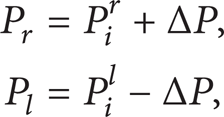
where P i is the initial pressure of PMs.
Therefore, the composition torque of the bionic joint can be determined by
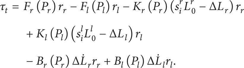
Extracting the spring force, the 3rd and 4th items, from (14), and combining (11′) and (13), yield the spring torque τ sj

where S j is the joint stiffness.
At the initial state, the shrinkage of left PM is the same as right PM for isomorphic mechanism, namely, s i l L0 l = s i r L0 r and ΔL l = ΔL r = 0. So in the initial position, output torque of the joint is 0, τ sj = 0, and we can get

The compliance is the characteristics describing the relationship between the joint rotations deform to the passive torque, always defined as the inverse of the joint stiffness. Combining (15) and (16), we can yield the compliance of bionic joint as
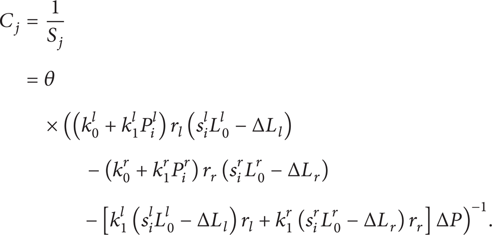
Equation (17) shows that the compliance is not relationship with the mass. So ignoring the mass of current bionic joint and arm is bad for getting the more precious dynamics but does not affect the compliance analysis.
3.3. Energy Efficiency Analysis
The joint's energy cost is the key characteristics to bionic performance and meanwhile is difficult to count. Under the same load, the energy consumption is approximately proportional to the PM length varying ΔL and the load gravitational potential energy varying ΔE p . Therefore, we adopt ΔL and ΔE p to scale the energy consumption. Pressure adjustments in both the inflation and deflation processes need supplying energy to the solenoid valve. For the agonist-antagonist pneumatic muscles joint, ΔL can be simplified as the sum of the contraction and elongation, such as ΔL r – ΔL l . The zero potential level is defined as when θ = 0, then the gravitational potential energy of the load can be obtained by

Equation (18) shows ΔE p will increase with the bigger h under given θ and L.
4. Analysis of Mechanism Parameters
4.1. Simulation Platform
Avoiding the difficulty of analytic solutions, we use the simulation to figure out the relationships between the mechanism parameters and the bionic swing. We establish the simulation platform using Simulink/SimMechanics shown in Figure 2.
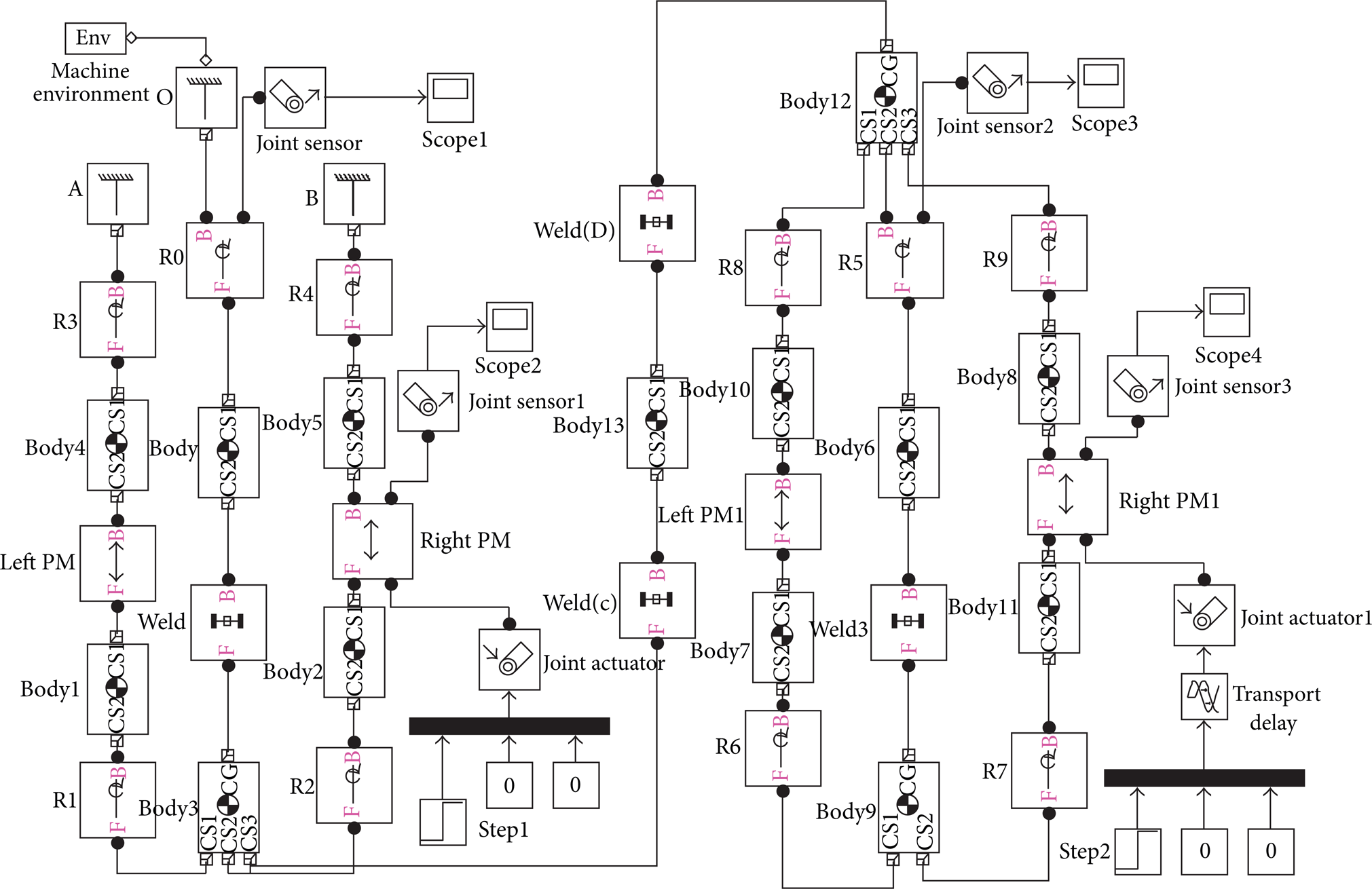
The simulation platform based on SimMechanics.
There is no PM module given in MATLAB/Simulink. Regardless of the radial varying, the PM is equivalent to the prismatic actuator with the driver module of (11). In Figure 2, “R” denotes the rotation joint, “Weld” fixed connection, and “Body” the link. “Joint Sensor” is used to get the joint angle and velocity. This simulation platform input is the slope increasing pressure that is transformed to the force supplied on the prismatic according to (11), and output includes each joint angle, velocity, and length varying of the PM. During simulation, the joint swing can stop when any constrain is not satisfied. This platform can be used to analyze the influence of the mechanism parameters to the bionic joint rotation quantitatively. The sample frequency is set to 100 Hz, and data float precision is 0.001.
4.2. Comparing the Nonlinear Contraction Model to the Circle Model
In order to illustrate the differentia between (2) and (3), we conduct the joint swing simulation with parameters shown in Table 1, and results are shown in Figure 3.
Simulation parameters.

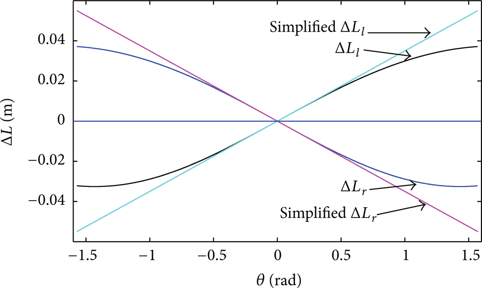
The relationships of ΔL – θ.
Figure 3 shows that the relationship reflected by (3) is close to (2) only when the angle is very small. As the joint angle increases, errors produced by (3) increase obviously. This is one of the reasons for large errors generated in trajectory tracking process in the literature.
4.3. The Effect of h on the Rotation Angle Scope
For anticlockwise swing, the right PM is the master diver. For symmetric mechanism, the joint's effective swing angle can reach the maximum when the antagonistic PM's maximum contraction equals the other PM's maximum elongation. So for getting the max swing angle, the below mechanism parameters are adopted

Other parameters are the same as Table 1. During the simulation, the master diver is inflated. Considering all the constraints, the relationships between bionic joint effective swing angles with varying h are shown in Figure 4.

The relationships of ΔL – θ under different h.
Figure 4 shows the following rules:
The joint effective swing angle increases when decreasing h under h > 0.
Under h ≠ 0, the contraction and velocity of the right and left PMs are different.
When h decreases from positive to negative,
In Figure 4, the black solid points connected by the dashed line denote the max effective swing angle under different h. The dashed line shows that the relationship of h to max θ is unsymmetrical, and the effective swing angle will reach the max when h = 0.
4.4. The Effect of r on the Rotation Angle Scope
4.4.1. Symmetrical Mechanism Anticlockwise Rotation
The joint width is set to r l = r r = r and varies between 0.025~0.04 m (step 0.005 m). Other parameters are the same as Table 1. The simulation results under all constraints are shown in Figure 5.
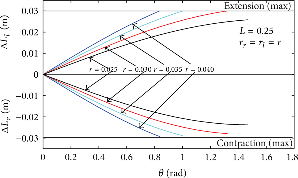
The relationships of ΔL – θ under different r with symmetrical mechanism.
As shown in Figure 5, the effective swing angle increases with decreasing r. Meanwhile, curve slope becomes smaller at the bigger θ, which means the rotation is more sensitive to the contraction of the PM. So it is difficult to achieve the precise position control at the bigger θ. Without considering the control accuracy, the rotation scope can be increased by reducing r.
4.4.2. Unsymmetrical Mechanism Anticlockwise Rotation
The joint total width, r l + r r , is kept as 0.070 m constant, and other parameters are the same as Table 1. The simulation results are shown in Figure 6.

The relationships of ΔL – θ under different r with unsymmetrical mechanism.
For the isomorphic PMs and the same installation prestretch rate, θ max increases with increasing r r under r r < r l . θ max decreases with increasing r r under r r > r l . For the unsymmetrical mechanism, the reason restricting the maximum angle of the bionic joint is the maximum elongation ((s i + s a )L0) of the left PM.
4.4.3. Unsymmetrical Mechanism Bidirectional Rotation
This section studies the unsymmetrical joint swing from left to right under r r ≥ r l . Set r r = 0.065~0.035 m (step 0.01 m), other parameters same as Section 4.4.2. The simulation results are shown in Figure 7.

The relationships of ΔL – θ under different r with unsymmetrical mechanism during bidirectional rotation.
Figure 7 shows the following rules:
Both
For the isomorphic PMs, increasing r
r
can make
For the isomeric PMs and r l = r r mechanism, we can make the initial contraction of the right PM less than left PM to increase the maximum swing angle θ max .
4.5. The Effect of r on the Energy Consumption
Equation (18) indicates the effect of h on energy consumption. In addition, the effect of ΔL r – ΔL l on energy consumption should be studied. Given h = 0, ΔL r – ΔL l will vary with r. For the unsymmetrical mechanism, r l + r r is kept as 0.070 m constant and other parameters are the same as Table 1. Set r l = 0.055~0.015 m (step is 0.01 m), and the simulation results are shown in Figure 8.

The relationships of ΔL r – ΔL l with θ under different r.
Figure 8 shows that ΔL r – ΔL l decreases with increasing rl. Attentively, the lesser ΔL means the energy saving. The energy consumption can be reduced properly through setting r l > r r .
4.6. The Effect of h and r on the Compliance
When the humanoid robot works in the human being living environment, the collision and contact between robot and human are inevitable. Therefore, for ensuring the human safe, the compliance is very important to bionic joint.
The simulation of the bionic joint compliance during swinging in anticlockwise is shown in Figure 9, and dynamics parameters are listed in Table 2.
PM's dynamics parameters.


The relationships between the compliance with r and h. (a) Unsymmetrical mechanism with h = 0; (b) symmetrical mechanism with r l = r r = 0.035 m.
Figure 9 shows the following rules:
the joint initial compliance is relevant to r, not to h.
For the symmetrical mechanism, the joint compliance increases when increasing h from the negative to the positive.
For a pair of the isomorphic PMs, the initial compliance increases when increasing r l .
The larger compliance is present with the larger θ.
Under collision, joint angle will be increased by impact torque suddenly. The joint compliance should quickly increase with increasing angle to give buffer for human. For safe coexitings of humanoid robot and human being, we should increase h or r l to get the abrupt curve between compliance with swing angle.
5. Optimal Design of Shoulder and Elbow Joints
5.1. Optimal Object
The primary objective of this paper is to design the more humanoid arm just considering the case swinging in the vertical plane. Mechanism design object is reference to the males aged 18–60 in southeast region of China. The optimal object parameters are shown in Table 3.
Human arm and swing parameters [18].

The angle scopes of both the human shoulder and elbow joints are asymmetry. This paper's optimal goal is to make the joint sizes and rotation angle scope of the bionic joint arm close to human arm. At the same time, try to reduce energy consumption and improve the joint's compliance as possible.
Noteworthy, the effects of mechanism parameters on different bionic performance are conflicting, so it is difficult to get the optimal effect for all bionic characteristics. We just can get the general optimal design by trials and errors.
5.2. Design of the Shoulder Joint
According to Table 3, design r l + r r = 0.082 m. In view of the maximum angle of shoulder swing forward (anticlockwise) is bigger than backward (clockwise); set r r > r l . Because θ max has an increasing tendency when decreasing r r as shown in Figure 7, design r r = 0.030 m, r l = 0.052 m. FESTO Company's MAS-10-xx type PMs were employed as actuator with L0 l = L0 r = 0.273 m, L l = L r = 0.250 m, and s a = 9%, s max = 20%. The maximum pretension rate of PMs produced by FESTO is about 2%.
As discussed in Section 4.3, set h < 0 to avoid the singular point appearing before C1. Without considering the contraction constraint of left PM, θ max under different h simulation is shown in Figure 10.
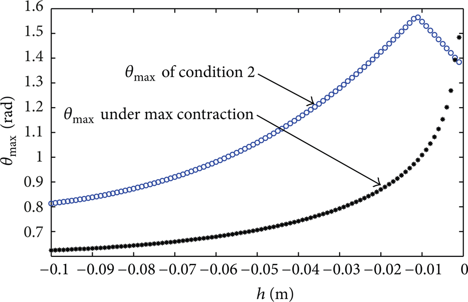
As shown in Figure 10, θ
max
of C2 is not monotonically increasing with decreasing
If the left PM installation and work performances are the same as the right, namely, using isomorphic PMs, Figure 11 shows that the left PM oversteps constraints when the right PM reaches the extension or shrinkage values. To solve this problem, we propose an optimal design procedure as follows,

The relationships of ΔL r , ΔL l with θ under same PMs.
Step 1. With the given parameters of the right PM, we can obtain the maximum contraction |ΔL max r | = 0.030 m and the maximum anticlockwise swing angle θ max = 1.392 rad according to Figure 10.
Step 2. Calculating (2) with θ max , we can obtain the maximum elongation of the left PM ΔL max l = 0.053 m. Thus, the length of the left PM without inflated is L0 l = L + ΔL max l = 0.303 m.
Step 3. According to Table 3, we set
Step 4. Substituting θ min = – 0.348 rad into (2′), we can obtain the maximum contraction of the slave PM ΔL min l = – 0.018 m.
Step 5. Set ΔLs
max
+ s
a
l
= ΔL
max
l
– ΔL
min
l
= 0.0707 m, and
Step 6. Calculating the precontraction ratio of the left PM,
According to ΔL
max
l
= (s
i
l
+ s
a
l
)L0
l
, the maximum elongation ratio of the left PM
In general, the left PM chosen should meet the parameters s max l = 23.34%, L0 l = 0.303 m, s i l = 17.44%. This optimal design with asymmetry PMs is easier to get the maximum forward swing angles.
The response rates

The shoulder joint
As shown in Figure 12, the accelerating performance of the common bionic joint (r
l
= r
r
= 0.041 m, h = 0) is poor, and appropriately decreasing h is beneficial to the better accelerating performance. However, the singular point is more likely to appear if h is increased in the symmetrical mechanism. Curve
5.3. Design of the Elbow Joint
According to Table 3, the width of the elbow is set as r l + r r = 0.075 m. The elbow can only flex forward unilaterally. So the single PM driver method is applied. The spring can be installed on the left side replacing left PM, which can eliminate the constraint of the maximum elongation and also can reduce the energy consumption. Without the elongation constraint of left side, r r should be reduced as small as possible to improve θ max . Considering the installation size, we set r r = 0.026 m, L = L0 r = 0.250 m, s i r = 0, s max r = 20%.
According to Figure 1 and (18), the maximum θ
max
only can be

The relationships of shrink – h.
As shown in Figure 13, θ max gets the maximum when h = – 0.019 m and the absolute value of slope is bigger than the others. This indicates that h = – 0.019 m is beneficial to getting the accurate position control and effective using the PM contraction. With the proposed elbow joint parameters, θ max = 2.08 rad close to the expectation value 2.09 rad. In addition, the fixed point of the left spring under the x axis (y < 0) can avoid the mechanism interference.
5.4. Comparative Analysis
Conventional 4-link joint is symmetric and h is 0. We can get the r l and r r of conventional joint by averaging the mean diameter of arm in Table 3. For fair comparing, the conventional and proposed joint use the same PM under same arm length.
The results comparing the human and conventional bionic joint to the optimal design are shown in Table 4.
The comparison of three joints mechanism and swing parameters.

Compared to the conventional mechanism, the angle range of the proposed shoulder is enhanced about 7% and the elbow about 42%. The contraction of two antagonistic PMs can be reduced about 7% (utmost) during the same swing scope. The optimization mechanism enlarges the swing angle range. For the bionic shoulder joint, the compliance can also be improved under r r < r l . For the bionic elbow joint, only a single PM is employed to drive the mechanism, which saves cost and makes θ max reaching the maximum angle of the human elbow flexion.
The mechanism and swing process are shown in Figure 14.
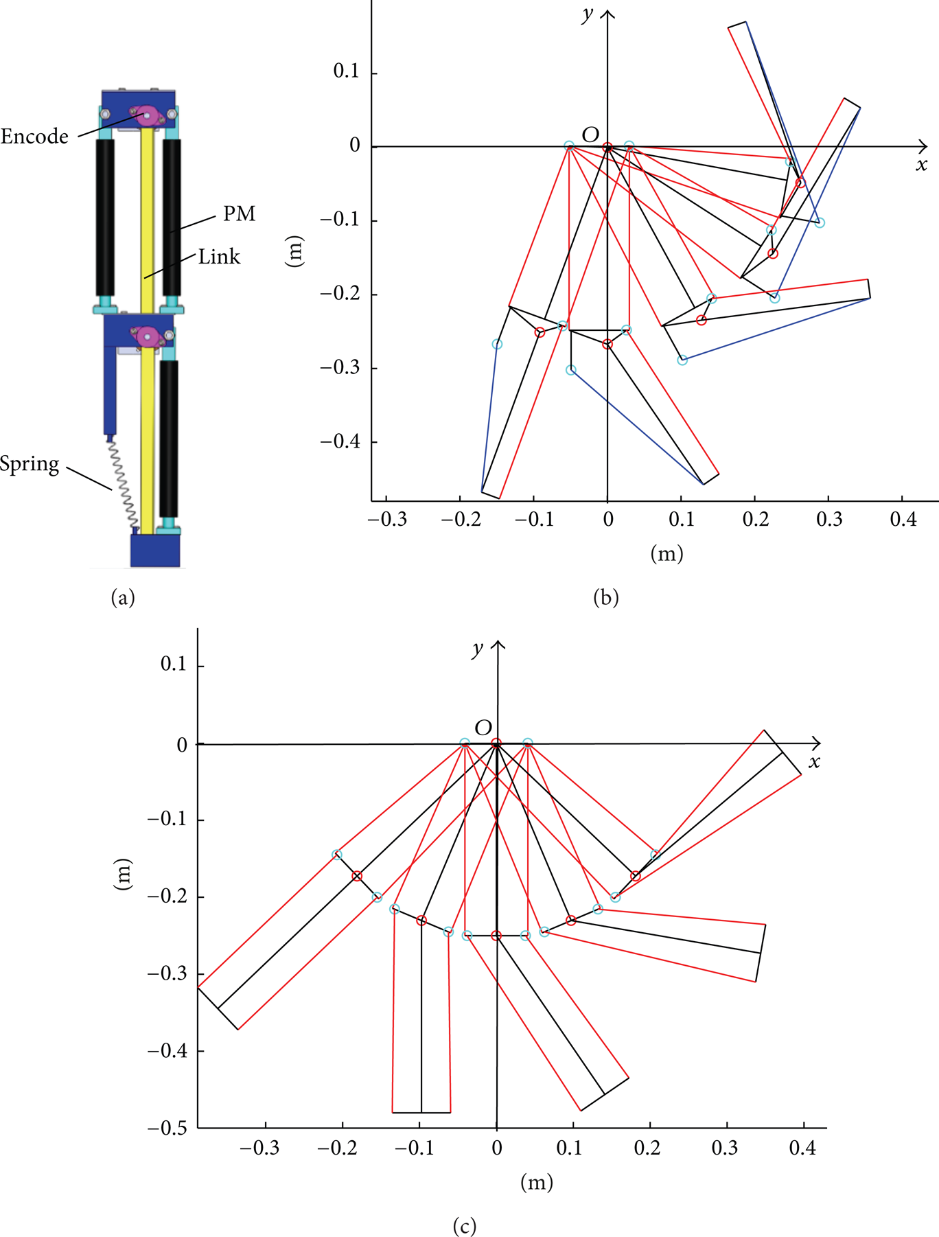
The sketch of proposed and conventional bionic arm. (a) Proposed virtual prototype; (b) proposed joint swing processing; (c) Conventional joint swing processing.
Both proposed shoulder and elbow joints have nonzero h, and different r l and r r as shown in Table 4. In Figure 14 (b), the 5-link mechanism of shoulder joint is not obvious due to h = – 0.002 m only. However, the optimal r l and r r make shoulder joint swing more like human. Comparing Figures 14 (b) to 14 (c), we are confident that the optimal h, r l and r r parameters make 5-link joint more advanced than conventional 4-link joint.
6. Conclusions
Taking anticlockwise swinging for example, this paper has analyzed the impact of three mechanism parameters on the bionic joint swing characteristics, and the shoulder and elbow joint are optimally designed. The analytic and simulation results have shown the following:
Swing space of the bionic joint can be improved by appropriately reducing h.
The anticlockwise swing maximum angle can be increased by reducing r r , and the energy consumption can be reduced synchronously.
Compliance of the bionic joint will be better through increasing h or r l properly.
It is conducive to use contraction of the PM effectively by employing the isomerism installation for the bionic joint driven by two antagonistic PMs.
Above-mentioned work is beneficial to develop the more anthropopathy artificial muscle joint. It is a great encouragement to our future work, intending to make the precision control of the PM joint angle easy and human-like.
Conflict of Interests
The authors declare that there is no conflict of interests regarding the publication of this paper.
Footnotes
Acknowledgments
This work was supported by National Natural Science Foundation of China (no. 50905170), Natural Science Foundation of Zhejiang Province (no. LQ13E050004), and Research Project of General Administration of Quality Supervision, Inspection and Quarantine of China (no. 201210076-2).