
Abstract
ZigBee is a protocol suite based upon IEEE standard 802.15.4 for the construction of low-rate wireless personal area networks. Since most of ZigBee devices are powered by battery, the power saving is an important issue. In the past several years, many solutions are proposed to extend battery life by reducing device transmitting and receiving time. However, few studies have noticed that most energy is consumed in sensing and monitoring rather than communicating activities, since the data rates in most ZigBee networks are low. Besides, energy will consume the most of those nodes which act as routers or are orphans that cannot join the network. In order to extend the life time of network, we proposed a dynamic topology reformation algorithm. The algorithm consists of a cluster reformation scheme for enhancing connectivity and a self-swapping method for averaging the loading of router nodes and end devices. As the experimental result shows, compared with the ZigBee standard, our method gains 6.02% to 15.13% improvement in network join ratio. And the role swapping balances the power consumption which makes the lifetime of the whole network 1.3 to 1.375 times longer.
1. Introduction
Wireless sensor networks are widely used in many applications. Generally, they are composed of a large number of sensor nodes which are deployed densely or randomly in a wide area. Hence, sensor nodes need to be of low power and low cost in signal processing and computation. The stabilized and accurate data transmission without missing or signal interference is also important. The position of sensor nodes is neither designed nor predetermined, so each sensor node does not know the relative positions of the others. Therefore, in a wireless sensor network, nodes should automatically self-organize their transmission networking by a self-organization protocol [1]. After sensor nodes collected data, they can transmit these data to gateway sensor nodes, and gateway sensor nodes transmit these data to the control center. Recent advancement in this field provides standards such as IEEE 802.15.4 and ZigBee.
The IEEE 802.15.4 defines the physical and MAC layers for low-rate wireless personal area networks (LR-WPAN) [2]. The physical layer specifies many features such as frequency bands, frequency channels, channel selection, link quality, power detection, and clear channel. The MAC layer defines two types of nodes: one is full function devices (FFD) and the other is reduced function devices (RFD) [3]. FFDs are applicable to all network devices. RFDs can only serve as a network end device, such as light switches, sensors, and transducers, and usually only connect with one coordinator (FFD) in the network.
Based on the IEEE 802.15.4, ZigBee specification defines the application layer, network layer, and correlative security strategies [4]. ZigBee defines three types of devices: coordinator, router, and end device. A coordinator is responsible for initializing the whole network, setting network parameters, and assigning addresses to nodes which joined the network newly. Besides, in order to ensure correct data transmission, the coordinator synchronizes all nodes in the network. Only FFDs can act as a coordinator. ZigBee routers are in charge of transmission, relaying data to other nodes in different location or out of the source's transmission range. ZigBee end device are responsible for sensing environment information, processing and storing the data temporally, and transmitting it to the coordinator or a control center.
Even though a ZigBee network features low power consumption, there are many studies that try to improve power consumption in existing standard implementations. In order to have better transmission quality and to extend network lifetime, many studies [5–8] are focused on searching for a good routing path to transmit data correctly and reducing power consumption. Some make nodes sleep when there are no data to transfer [7]. Different from this strategy, we propose a dynamic topology reformation algorithm (DTRA) to alleviate this problem. The algorithm consists of a cluster reformation scheme and a self-swapping method. The first part focuses on reducing the isolated nodes by letting the isolated nodes join the network when the joined nodes' communication link changes. There follows a method that swaps nodes between ZigBee router and ZigBee end device based on their residual energy. The proposed method is expected to reduce and balance the power consumption in network.
The rest of this paper is organized as follows. In Section 2 we review related studies for power saving in ZigBee networks. In Section 3 we describe our dynamic topology reformation algorithm. The experimental environment and the results are shown in Section 4. Finally, in Section 5 the conclusion and the future works are drawn.
2. Related Works
ZigBee devices are addressed by thier
In [11], an enhanced self-configuration method is proposed for the creation of a robust ZigBee network and the improvement of the problems of orphan nodes. Their method [11] is capable of dynamically reconfiguring the tree, avoiding the orphan propagation problem, as well as fast recovery. Build upon the physical layer and media access control defined in IEEE 802.15.4, ZigBee network is working on 2.4 GHz frequency. The channel is also use by many other sources such as IEEE 802.11, Bluetooth, and so forth. Thereby, the network may suffer from frequent link breakages. All the sudden isolated nodes perform reassociation procedure, which may bring much delay due to reconnection overhead, and cause additional energy wastage. Finally, the orphan propagation problem will bring a serious chaos to the network.
Besides, from the whole network perspective of view, a life of a sensor network ends when the first few nodes become a failure rather than the last node blackouts. For this reason, researchers propose various techniques to minimize power consumption on ad hoc networks [4, 5, 7–9]. Most of them are focused on routing optimization. According to the improvements of these routing algorithms, they also can reduce power consumption by increasing data transmission correctness and reducing data retransmission time. However, we focus on power saving and no particular routing protocol is used.
Low energy adaptive clustering hierarchy (LEACH) [15] is a cluster-based algorithm. It utilizes randomly rotated cluster headers to distribute the energy consumption evenly among sensor nodes in a network. By coordinating each node in the cluster, it improves the scalability and balances the energy consumption. However, the cluster in LEACH is not equally distributed and not suitable for time critical applications.
There are papers proposed to improve LEACH [16–18]. In these, Manjeshwar and Agrawal [16] proposed a reactive protocol named TEEN. Unlike the proactive LEACH, it is a reactive protocol based on the defined energy threshold. The MECH [17] proposed by Kuo constructs clusters based on the radio range and the number of the cluster members. The cluster topology in the networks is well balanced during cluster construction. Besides, there are some who discuss power consumption measurement and wake-up solutions [19–23]. We know that a proper energy consumption model is a foundation for developing and evaluating a power management scheme in the wireless sensor networks. Wang and Yang [19] proposed a general energy consumption model which was based on their actual hardware structure in WSN devices, for they thought that it is important to model the fundamental energy consumption behavior of real wireless sensor network devices before optimizing or developing an energy-aware design. Khan et al. [20] proposed a model named FZepel for cross-layer stack analysis. The FZepel is an execution-based power assessment method based on an RF level power measurement. However, this model does not balance the use of each node so that a certain node may die much earlier than others. Ghazvini et al. [21] proposed a new MAC protocol called EMAC. They believed that nodes in idle state needed to enter a shutdown state when there was no data to be sent to the coordinator. Wendt and Reindl [22] proposed that a wake-up solution reduces the on-time periods of the sensor nodes, since sensors are required to be online only when data needs to be acquired and transferred. A space diversity approach which constitutes the basis of the demonstration hardware reported is proposed in that paper. Antonopoulos et al. [23] proposed a method for minimizing power consumption in wireless sensor networks using the ZigBee protocol. The idea is a kind of time-division multiplexing operation. They segment many time slots and assign each to a ZigBee device. The devices only work in their own time slot. However, the scale of the experimental ZigBee network in this paper is so small that it is not applied to real world ZigBee networks, which usually consist of many sensor nodes.
To sum up, a good power saving approach should reduce the power consumption and extend the network lifetime. It also needs to be simple enough to be implemented. In this paper, the DTRA is proposed for ZigBee sensor networks.
3. The Dynamic Topology Reformation Algorithm (DTRA)
In this section, we detail our method “Dynamic Topology Reformation Algorithm,” which combines a cluster reformation scheme and a self-swapping method.
3.1. The Cluster Reformation Scheme
In previous sections, we described the isolated node problem. Based on [11], it is possible to find several shiftable nodes that can shift to the same candidate node, but the candidate node can only accept one child to join due to the restriction of the algorithm. So our approach tunes the method for enhancement by a candidate chosen mechanism. The mechanism is used to select a shiftable node which can make the potential parent accept isolated nodes as many as possible. The cluster reformation scheme can be separated into two parts. The first one is the isolated joining algorithm and the other is the best candidate decision mechanism.
The procedure of the isolated joining has the following steps.
Step 1.
An isolated node sends a join request to the potential parent.
Step 2.
The potential parent searches its children that are shiftable if it has no capacity to accept the isolated node.
Step 3.
Operate the best candidate decision mechanism if there are more than two shiftable nodes that can shift to the same candidate parent.
Step 4.
The chosen shiftable node is shifted to the new parent.
Step 5.
The potential parent can reaccept the isolated node.
Step 6.
If there exist other isolated nodes, go to Step 1 again.
The best candidate decision mechanism used in Step 3 is shown in Figure 1. There are three cases when these shiftable nodes have the same candidate parent. The first one is that the isolated nodes are all end devices. Because only the coordinator node or router nodes can accept the join requests, even if the end device can be accepted by the potential parent, it cannot accept the other isolated nodes. Thereby, if there are more than two isolated nodes of end devices, the one with the smallest depth will be chosen because the power consumption is lower when transferring data back to the coordinator.

The best candidate decision mechanism.
The second case is that all the isolated nodes are router devices. Since all isolated nodes are capable of routing, the number of nodes affected becomes the decision criteria. Within the communication range of each isolated node, the number of the unconnected nodes will be scanned first. These nodes will notify the potential parent with a join request attached with the number. Finally, when the candidate parent wants the shiftable nodes, it will choose the router device that has the most unconnected nodes within its communication range. So it may have additional capacity to accept the other isolated nodes within its communication range. Therefore, it will further reduce the isolated nodes.
The last one is that there are end device and router devices. According to the previous two cases, we will choose the router devices to be the first candidates since they can reduce more isolated nodes.
3.2. The Self-Swapping Method
The self-swapping method is performed on a beacon-enabled ZigBee network. Network synchronization is required. In order to synchronize all devices in the network, ZigBee coordinator and ZigBee routers are required to send beacon message to other devices. The coordinator plays an important role when a ZigBee network is constructed. The coordinator broadcasts a connection beacon message at the beginning of the first timeslot to other devices. On receiving this connection beacon, devices are able to start their connection process, and they can get their own timeslot when this process of sending connection beacon is completed. At the end of the timeslot, the coordinator sends time synchronization beacon to other devices which are on the same location with the coordinator. If these devices in the local network read the time information differently, wrong transmission and inaccurate data reading may occur, and extra time and power may be needed to retransmit data. In addition, many devices which are out of transmission range of the coordinator also need to be synchronized. ZigBee routers are required for this process. The router processing will be explained later.
After the beginning of the first timeslot for sending beacon message, the coordinator starts the processing of next timeslot. Other devices can transmit data only in their own timeslot. Transmission “timeslot + 1” means that the device in the next timeslot is ready to work. The procedure of the coordinator is shown in Figure 2(a).

The diagram of node processing.
ZigBee routers are responsible for retransmitting messages to a farther location. When the coordinator cannot transmit its beacon message to devices out of its transmission range, routers share the responsibility. Just like other devices, routers are able to start their connection process and get their own timeslots. Every router must relay the time synchronization beacon immediately after it hears the time beacon from the coordinator. In addition, every router also needs to broadcast a connection beacon so that nodes covered by their transmission ranges can start the connection process in the network. All devices, including end devices, can work on their own timeslots.
The operation of a router consists of not only transmitting and receiving but also sensing. Thus the power of routers is consumed quickly. Therefore, we believe that a residual energy evaluation procedure will be helpful in power saving. Figure 2(b) is the diagram of the operations of a router.
The swapping decision method is implemented on ZigBee routers and end devices rather than the coordinator. The reason is that the coordinator is responsible for administering all networks, such as parameter setting and address assignment; hence a swap between the coordinator and another device will lead to the large overhead of reinitialization. Generally, ZigBee routers consume more power than end devices, for they usually have to not only relay messages but also monitor their environment as end devices do. Of course, node energy consumption depends on the real application environment. To balance energy consumption, swapping ZigBee routers and end devices seem reasonable and suitable. Indeed, a reasonable situation is that there are candidates that are one-hop node away from the router for swapping. It is not reasonable to swap nodes which are in remote locations, for it will cause more packets to be transmitted and more delay time. Furthermore, end devices usually only connect to one FFD (coordinator or router), so it is convenient to perform end-device/router swap if required. A suitable situation is that a one-hop-away node has higher residual energy than that of the target router. To evaluate the residual energy of a battery, note that, in the progress of battery energy consumption, the change of voltage is slow; so we do not need to frequently compute the remaining battery energy of the candidate nodes for swap. Only if a significant battery voltage changing occurs, we compute the overhead of swapping and determine whether to swap or not. The detailed steps of swapping are as follows.
Step 1.
When the residual power of a certain ZigBee router is lower than a certain threshold, the swapping procedure is triggered. If the voltage is obviously down, it starts the energy comparison procedure.
Step 2.
As the router makes the decision, it needs to know whether the nodes can be swapped or not. If there is no node whose residual power is more than the router, it stops the comparison procedure and does not swap with any node. Otherwise, it proceeds with the next step to select a node to swap with.
Step 3.
To know which nodes can be swapped with the router, the router needs to compare the residual energy between them. It needs to compare all one-hop nodes and chooses one to swap.
Step 4.
The router evaluates the overhead of swapping. If a suitable end device can be found, the swapping will be performed.
We know that if a router swaps with an end device, it requires exchanging information. First, router transmits a swapping message to the end device indicating its decision and stops its routing job but maintains sensing. The message includes swapping notification and routing information, such as parent, child node members, and routing table update. Then, the new router needs to send messages to other nodes to notify that “I am the new router.” So, the overhead consists of these messages and information changes.
The energy consumed in the swap operations by a node includes the energy used for receiving (
Analogous methods are used in [24, 25] to evaluate the power consumption. However, we assume that the sleep and idle mode energy consumption can be ignored which is because that power consumption in the sleep/idle mode for a short period is too small to measure. By the way, nodes will enter the idle mode when there is no data to transmit. The router swapping decision procedure is shown in Algorithm 1.
if (eZR < ENERGY_THRESHOLD) { if (eZED for ( reZED } if (the maximum reZED return node i; else No swapping; } else No swapping; } else No swapping;
3.3. The Complexity Analysis
The cluster reformation scheme and the self-swapping method will be analyzed and their complexities will be calculated here.
Since all the devices except the coordinator are deployed randomly, we assume that these devices are within the communication range, which means all nodes can see the others. The analysis and complexity of the cluster reformation is carried out in two cases: the worst case and the best case.
The best case is shown in Figure 3. The complexity depends on how many node shifts are needed before the isolated node can join the network. In the best case, only one node is shifted. Here, one node shifting is denoted as a constant time

The best case.
On the other hand, the worst case is shown in Figure 4. Clearly, the topology of the network is near to a full-connected binary tree. Assume the nwkMaxDepth is d. The worst case for an isolated node to join the network is to shift almost all the nodes on the deepest level d. Therefore, it needs to shift exactly

The worst case.
Another overhead of the proposed cluster reformation scheme is additional memory required to store the count of unconnected nodes within the communication range of router devices. Only router devices which are isolated require this space. However, we cannot identify the situation of connectivity in the beginning since all nodes are randomly deployed. Thereby, each router device needs an additional field to record the count even if it is not an isolated node. So the space cost is
For the self-swapping method, after residual energy evaluation, the node with the maximum residual energy is selected from the set of one-hop neighbors for role swap. Assume that there are n nodes in the one-hop neighbor set. The operation of selection is not only to select the maximum energy node in the n candidate end devices, but also to calculate the residual energy after potential swapping, which means that all nodes must be sorted based on their current energy level first and then examined one by one. We use quick sort in this sorting operation. Therefore, the operations in best and worst cases act like the quicksort sorting algorithm. The best case occurs when these n numbers are split in to two lists on average. That is, two sublists contain the same number of elements. In this case, we can express a recurrence formula as follows:


So, we can know that the time complexity in best case is

Therefore, the worst case is
4. Results and Discussions
For evaluating our cluster reformation scheme (named Z-CRS hereafter), we simulate it and compare it with others. We focus on the performance of join ratio, which is computed as formula (4). Thereby, the experimental results are shown according to three types of methods: ZigBee standard, ZCIM (ZigBee connectivity improving mechanism) from [8], and our Z-CRS:

The simulation parameters are shown in Table 1. The coordinator device is in the center of the area, and the router devices and end devices are deployed randomly. In this simulation, the sensor mobility of all the devices is static.
Parameters setting of simulation environment.
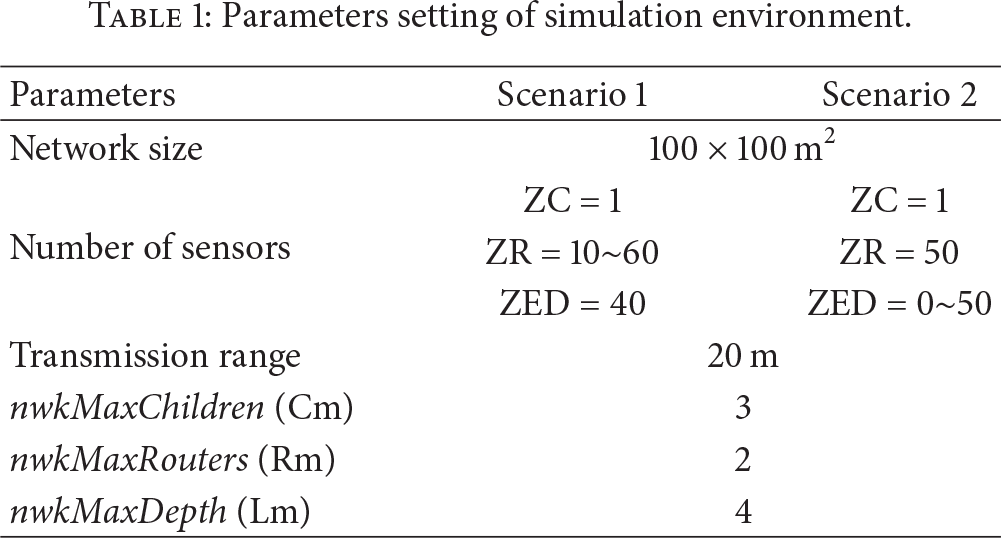
Two scenarios are constructed. The first one has 40 end devices with 10 to 60 router devices. The results of three different methods are shown in Figure 5. It shows that our method has an improvement of 2.01% to 13.78%, compared to the ZigBee standard, and 0.86% to 3.47%, compared to ZCIM. The increasing of join ratio is not obvious when the number of ZigBee routers is between 10 and 20 because nodes that can accept join request are too few. When the number of total nodes is small, the probability of these shiftable nodes choosing the same candidate parent is low. Thereby, the join ratio is almost the same with ZCIM. However, when the number of ZigBee routers increases to 40, the join ratio starts dropping. In fact, the dropping of join ratio is unavoidable because the connectivity is saturated and the total number of nodes is still increasing. It causes the join ratio to decrease.

Results of different numbers of end devices.
The second one fixes the number of router devices to 50 and changes the end devices from 0 to 50. The total nodes in both scenarios are from 50 to 100. The results of three different methods are shown in Figure 6. For this scenario, our Z-CRS has 6.02% to 15.13% improvement, compared with ZigBee standard, and also has 0.19% to 5.42% improvement, compared with ZCIM. The join ratio starts dropping when the number of ZigBee end devices increases to 20 because the connectivity is saturated and the total number of nodes is still increasing. The ZigBee end devices have no ability to accept join requests. Therefore, when there are too many end devices, the join ratio will not increase.

Results of different numbers of router devices.
To evaluate our cluster reformation scheme, since the residual power cannot be measured in a simulation environment, we conduct the experiments with ten real ZigBee nodes. These ten nodes consist of microcontrollers (ATmega128L), wireless communication chips (CC2420), various kinds of sensors, and an antenna. The scenario is shown in Figure 7.

Experimental scenario.
One node is used as a sink which is responsible for collecting the data transmitted by routers or end devices. Two nodes are used as routers. They connected to the sink directly. The rest seven nodes are used as end devices, which are responsible for sensing. To simulate a real world case, we assign the routers two jobs, which make the routers consume more power than end devices. To focus on the power consumption of the method we proposed, we do not take new nodes, address assignment, and so forth into consideration. We compared the proposed method with the ZigBee standard. Figure 8 shows the average residual energy of ZigBee routers and end devices. As the system runs, the residual energy of routers became lesser. However, we can see that the residual energy of routers in the ZigBee standard operation was smaller than that in the proposed method. We believe that the consumption rate of energy is faster if there is no node to share the energy consumption of routers. In the proposed method, routers could choose another node to be a new router to share the energy consumption, so the exhaustion rate of energy is slower.

Average residual power.
The residual energy of end devices in our method is lesser in most cases. Because of node swapping between routers and end devices, the system balances the energy consumption of nodes so that the alive time of routers could be longer. On the other hand, if the router does not work, one method to solve this problem is that end devices may transmit the data to the sink directly. It results in higher power consumption of the end devices to transmit data, especially for the nodes far away from the sink; otherwise it does not transmit at all. Therefore, even though the end devices in the ZigBee standard operation spend less energy consumption at the beginning, they need to spend more energy to transmit data when the routers are dead.
Figure 9 shows the number of live nodes in the experimental network. Referring to Figure 8, we learn that because of swapping nodes, the energy consumption is better balanced, so the alive time of the routers is longer in our method. If the power of the routers is drained, then end devices need more energy to transmit data to the sink directly, which will make them exhausted sooner.

The number of existence nodes.
We show the proportion of lifetime in Table 2. We detail the result in two aspects and divide it into two cases to discuss. In case 1, both of system's relaying lifetimes, defined as the period from the system starting time to the time when no router is working, are compared. If the relaying lifetime of the ZigBee standard operation equals 1, the relaying lifetime of the proposed method is about 1.375. We believe the relaying lifetime could be extended by swapping nodes.
The improvement of lifetime.
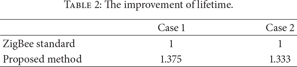
In case 2, the definition of lifetime is the duration of the existence of the network. In this case, when routers do not work we still execute the experiment. The method lets the end devices directly transmit the collected data to the sink. Finally, when the sink does not receive any data, whether end devices die, the experiment ends. We can see that the lifetime in the proposed method is about 1.3 times as long as that in the ZigBee standard operation. Therefore, extending router lifetime can also extend end device's lifetime.
5. Conclusions
Connectivity and power consumption are important issues in wireless sensor networks. People usually hope for longer working time of the devices with a limited energy capacity. In this paper, we proposed a dynamic topology reformation algorithm to increase connectivity and reduce the power consumption in ZigBee sensor networks. The algorithm is combined with a cluster reformation scheme and a self-swapping method.
For the cluster reformation scheme, the experimental results show that the approach can increase the join ratio of the ZigBee networks. It will also enhance the performance of the entire networks.
Besides, with our self-swapping method, a ZigBee router can choose the best one-hop neighboring end device for swapping. The purpose is to employ other nodes to share and balance the energy consumption of the nodes with energy demanding jobs. The experimental results show that swapping nodes can extend the lifetime of routers, as well as that of end devices, even though some overhead is involved in swapping.