
Abstract
In this paper, we present a technique to maximize the lifetime of SRAM-based FPGAs in space mission. We focus on recovering permanent faults induced by SEE (single-events effect). In our technique, we use a fix-sized fault detection module to detect permanent faults and propose a permanent fault recovery mechanism for fault recovery. By using partial reconfiguration, we develop a system lifetime estimation model to find the optimal partition for designing the module-based fault recovering with the maximum system lifetime. We conduct experiments with a set of real applications including SpaceWire, Wavelet, AC97, MEPG-4, 8086, and Ethernet on Xilinx XUP platforms. The experimental results show our technique can effectively improve the lifetime compared with the previous work.
1. Introduction
Since the first prediction of SEE (single-event effect) in microelectronics in 1962 by Wallmark and Marcus [1], researchers and engineers who work on space-based systems have been concerned about the effects of cosmic rays on mission reliability. Radiation environment in aerospace is shown in Figure 1. This concern was realized in 1975 when an anomaly in a spacecraft system was first attributed to the passage of an energetic heavy-ion [2]. Since that time, a long list of single-event effects in semiconductor devices and integrated circuits has been compiled. Some of these effects result in a “transient fault,” which causes no permanent damage and can be reset by applying the correct signals to the device. Other effects so-called “permanent fault” can damage the semiconductors permanently. Although these permanent faults can be mitigated by using radio-hardened components, radio-hardened components have a very low performance and cannot meet the requirements in current space exploration mission. Hence, new substitutes with both high reliability and high performance are needed in space mission.

Illustration of radiation environment in aerospace.
FPGAs (field programmable gate arrays) have many advantages over microprocessors for space-based applications. A variety of projects have demonstrated the benefits by using FPGAs in spacecrafts [3, 4]. For example, the Mars rovers use FPGAs for motor control and landing pyrotechnics [5]; the Australian satellite FedSat uses FPGAs as part of its high-performance computing payload [6, 7]. SRAM-based FPGAs are especially appealing due to their in-site reconfigurability and high performance for signal processing tasks. While SRAM-based FPGAs offer a number of unique benefits for spacecraft electronics, they are also susceptible to SEEs, which induce both transient and permanent faults in SRAM-based FPGAs. While transient faults can be recovered by reconfiguring the same resources, permanent faults require spare resources allocated in the FPGA to replace faulty resources. Therefore, partition and placing of an application with partial reconfiguration can affect the system lifetime.
Several approaches have been proposed to solve transient faults by using partial reconfiguration in SRAM-based FPGAs. A method using read-back and scrubbing is introduced in [8]. Read-back is based on periodically reading the configuration memory of the FPGA to detect if a transient fault has occurred. This technique can fix errors by creating the necessary reconfiguration bitstream, through a small bit manipulation approach [9], and comparing the read-back file and the original one. Scrubbing [10] is a method to correct SEUs, in which it performs a periodic reloading (usually with the same frequency of read-back) of the entire configuration bitstream, no matter whether an error has occurred or not. In [11], a duplication-based method is proposed to recover transient faults. The method applies concurrent error detection techniques to monitor the health of the system and to trigger the reconfiguration for the part with faults. In [12], the authors proposed a fault-tolerant reconfigurable architecture based on island-style FPGAs. This architecture contains “autonomous-repair cells” that can repair transient faults autonomously and dynamically. All of the above approaches cannot recover permanent faults.
There have been studies to solve permanent faults. In [13–15], a method based on STARs (self-testing areas) is proposed to test specific offline actions of a device, and the STARs are moved across the FPGA to cover all the off-line sections [13–15]. Although STARs can mitigate permanent fault, they introduce a big time overhead and cannot correct permanent faults in module-based FPGAs. A tile-based solution is presented in [16–18]. In this technique, an FPGA is divided into small partitioned tiles/blocks that have fixed interfaces to other tiles. Diagnosis can locate faulty resources with a granularity smaller than the dimension of a tile, such that faulty resources can be replaced with the spares in the tile. In [16, 18], a hierarchical model is proposed. The model has two hierarchical levels of redundancy: at the lower level, the FPGA is organized with fixed tiles, and each tile includes spare resources; at the higher level, faulty tiles can be replaced with spare tiles.
In [16, 19, 20], a coarse-grained redundancy model is presented, in which spare resources are lumped into tiles or columns. When faults are detected in a column, the whole column is marked as faulty and replaced by a spare column. In [21], the authors presented an efficient on-line failure detection method and integrated it into a reconfigurable system for executing and testing multiple automotive inner cabin functions. These methods also allow a certain degree of failure recovery, and they may provide solution that can heal the system itself from advanced faults. By using the strategy of redundancy, several techniques have been proposed to mitigate faults [22–26]. The triple modular redundancy (TMR) is one of the most commonly used methods, in which three identical functional blocks are utilized for the same functions and their outputs are checked and decided by a majority voter. The TMR introduces too much cost overhead [27]. In all of the above methods, the system lifetime is not considered.
In this paper, we propose a reconfigurable module-based fault recovery mechanism on SRAM-based FPGAs. We divide an FPGA-based application into a number of function modules and add a fix-sized fault detection module for each function module. We present a lifetime model to show the lifetime of an application, and based on this, an optimal partition can be obtained with different sizes of function modules.
To evaluate the effectiveness of our proposed technique, we conduct experiments with six real applications on Xilinx XUP platforms. The experimental results show that our technique can effectively improve the system lifetime compared with the previous work.
The remainder of the paper is organized as follows. In Section 2, we present the background. We introduce the system lifetime model and our optimal partition algorithm in Section 3. In Section 4, we present the experimental results. In Section 5, we conclude the paper.
2. Background
In this section, we present the background for the space radiation and its effects on FPGAs.
Integrated circuits operating outside the earth's atmosphere are exposed to a radiation environment that is much different from the radiation found on earth. Figure 2 shows the distributing of energetic heavy-ion in different altitudes above the earth. It can be observed that the radiation level increases with the altitude.

Illustration of a radiation environment in aerospace.
High-level radiation may influence normal operations of a semiconductor-based device. SEE is caused by protons and heavy ions emitted by the sun (i.e., solar particles), galactic cosmic rays, and particles trapped in the earth's magnetic field [28]. SEE causes both transient and permanent faults on electronic components. Transient faults can be reset by applying the correct signals to electronic devices. Typical transient faults include SEU (single-event upsets), SEL (single-event latchup), and SEFI (single-event function interrupt). Permanent faults cause permanent destruction of electronic devices and cannot be recovered. Typical permanent faults include SEB (single-event burnout), SEGR (single-event gate rupture), and SESB (single-event snap back).
With respect to radiation, SRAM-based FPGAs suffer from the same problems as other semiconductor devices. For transient faults, we can recover it by reconfiguring resources, while permanent faults require spare resources allocated in the FPGA to replace faulty resources after permanent faults are located. In this paper, we focus on permanent faults.
SRAM-based FPGAs are suitable for space mission with high density and reconfigurability compared with radiation-hardened antifuse parts. An FPGA consists of many basic configurable logic blocks (CLBs); CLB is the basic configurable unit, so the size (or the occupied number of CLB) of each reconfigurable module should be the multiple of the size of one CLB. One SEE-induced permanent fault can only lead one CLB to be damaged. Nonoccupied resources and connections among CLBs are fault-free from the radiation effects. By utilizing a set of fault-free resources and excluding the faulty ones, faulty resources can be replaced by partially reconfiguring the FPGA with an alternative configuration that preserves the same logical functionality.
3. Fault Recovery
In this section, we present our fault recovery mechanism. A given application can be divided into independent function modules, and each module is with the same size. For each function module, a fault detection/location module is added for fault detection and location. Therefore, an actual module with fault tolerance consists of a function module and a fault detection/location module. Without loss of generality, we name actual modules as m1, m2, m3, …, m i .
Following the size of an actual module, we divide the FPGA into a number of cells and sequentially mark cells as c1, c2, c3, …, c i . The size of each cell is the same and equals the size of an actual module. As randomly placing actual modules may lead to routing problem, we first calculate how many cells will be sequentially used. Then we place the application in the FPGA following the shape and the topology of the used cells and divide them into function modules with Xilinx PlanAhead. For each function module, we add a fault detection/location module. With PlanAhead, we place actual modules in sequential cells in an FPGA by matching the SN (serial number) of actual modules and cells, as illustrated in Figure 3.

Illustration of cells partition and module placement.
The work flow of our fault recovery mechanism is shown in Figure 4. Basically, when faults have been detected in one module, we will shift this module and all modules following it to available cells. As illustrated in Figure 5, if we detect that m9 is faulty, we will shift m9 and its following models, m10, …, m15, to available cells one by one. Then we replace and reconfigure the new layout on the FPGA. This fault recovery mechanism repeatedly works while permanent fault occurs in any module until all available cells have been used up. Due to abundant routing resources in an FPGA, in our experiments, we found that every different layout can work well without routing/interconnection problems in six real applications.

The work flow of our fault recovery mechanism.

Illustration of our fault recovery mechanism.
4. Optimal Partition
In this section, we present a technique to find the optimal partition to maximize the system lifetime. We first propose a lifetime model and show how to find the maximal system lifetime and its corresponding optimal partition. Finally, an example is given to illustrate the technique.
The size of a given FPGA is represented as S, the size of an original application system is A, and the size of the fault detection module is f. Suppose we can divide an original application system into n function modules, and the size of a function module is a, where A = a × n. Because of the characteristic of FPGAs, a should be the multiple of integers. The size of an actual module is m = a + f. The size of an application with the fault detection modules is

The free size of the FPGA after the initial configuration is

Because the resources of an FPGA are limited, the reconfiguration/recovery times are also limited. In our technique, the system recoverable times are

As SEEs arrive randomly, the fault occurrence process can be modeled by a Poisson process as shown in (4):

In (4), P k (t) is the fault occurrence probability, λ is the Poisson rate, t is the observation time and k is the fault occurrence times. For a normal SEE counting, λ = 1. Considering our fault-tolerance size ratio and fault-free nonoccupied CLBs in the FPGA, λ should be

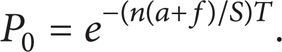
In the above equation, t is the observation cycle T. Because k is unknown, it is hard to obtain the fault occurrence probability. However, it is easy to get the nonfault occurrence probability while k = 0; that is,
Then the fault occurrence probability can be calculated as follows:

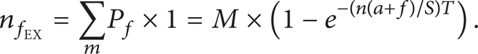
In one observation cycle T, suppose there are M permanent faults. Then, the expected fault occurrence times are
The expected time interval between each pair of faults or expected system running time between each pair of faults is

With our fault recovery mechanism, the system recoverable times are also the number of faults which occurred before the system fails. Therefore, the expected system lifetime can be obtained by summing up all the expected intervals between each pair of faults as shown below:

In order to find the optimal partition, we calculate all expected system lifetimes with all possible module size numbers from (10). Because the module size a should be an integer, we find all possible integers for module size partition and obtain the maximal TMAX and its corresponding optimal partition. We propose Algorithm 1 to select the integer module size partition and find the maximal TMAX and its corresponding optimal partition.
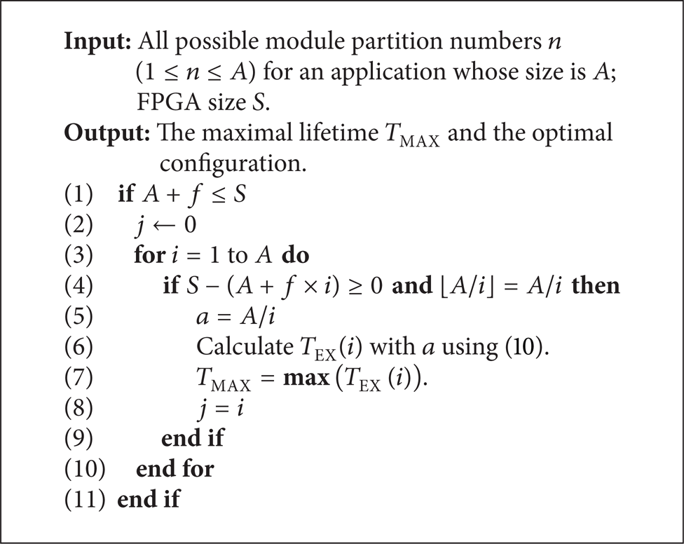
Obtain the maximum expected system lifetime TMAX and its corresponding partition.
Algorithm 1 presents a method to find the maximal lifetime TMAX and its optimal configuration by using (10). S – (A + f × n(i)) ≥ 0 is used to guarantee that the total size with the fault detection modules is less than the size of the FPGA. ⌊A/n(i)⌋ = A/n(i) is used to guarantee that it is an integer partition.
We use SpaceWire, a commonly used communication protocol in spacecrafts, to illustrate the work flow of our technique. SpaceWire has 112 CLBs. We set the observation cycle T as one year, the fault ratio M as 122 times per year, and the FPGA size as 3424 CLBs. First, we input every module number n (n = 1 ~ 122) into (10) and let a = A/n. Hence, we get 122 calculated expected lifetimes from (10) with 122 different module numbers, as shown in Figure 6. Because a module size a should be an integer, by Algorithm 1, we select the integer partitions from those 122 outcomes. The curve in Figure 6 shows all integers obtained and corresponding to expected lifetimes. In Table 1, we compare the system lifetime from the optimal partition and some other partitions.
System lifetime comparison between optimal partition and other partitions for SpaceWire.


Illustration of searching optimal maximal system lifetime.
5. Experiments
In this section, we present and analyze the experimental results. We first introduce the experimental environment. Then we present the lifetime metric and measurement method. Finally, the experimental results are given and discussed.
We evaluate our system lifetime model on the XC2VP30 Xilinx XUP FPGA platform. We conduct experiments with six real applications: SpaceWire communication node (from European Space Agency), Wavelet image compressing, AC97 audio encoding and decoding (a modified demo from Xilinx), MEPG-4 video decoding (a modified demo from Xilinx), 8086 IP core, and Ethernet web service (a demo from Xilinx). We obtain the system lifetime of each of these six applications with the optimal partition. Additionally, we test three other different partitions for each application.
5.1. Experimental Environment
In our experiment, Xilinx XUP Virtex-II Pro development kit had been used as our validation platform, which has an FPGA chip XC2VP30-FFG896 with 3424 CLBs, and we use Matlab as a generator for fault simulation. Our layout design and modification tool is PlanAhead 9.2.7. For permanent fault simulation, we generate a permanent fault sequence with the Poisson process. The data for permanent faults simulation comes from NAOC (National Astronomical Observatories, Chinese Academy of Sciences), which are 122 permanent faults per year averagely at 14 MeV neutron and 85°C.
5.2. Performance Metrics and Measurement Method
Permanent faults by SEE are counted by years [29, 30]. To speed up our experiments, we simulate one year's permanent faults in one minute. The faults occurring in FPGA follow the discrete uniform random distribution. Therefore, we generate a discrete uniform random sequence for fault location simulation and the range of the sequence is from the minimal SN to the maximal SN of cells. To simulate permanent faults in FPGA, we place an empty module in a damaged cell, so the logic resource of this cell cannot be used anymore.
In our experiments, we divide an FPGA to cells with the same size and sequentially mark cells (see Section 3) and then configure the initial layout with the partition (including fault detection modules) of an application. SEE-induced permanent faults are generated as described above. Once a simulated fault occurs, the fault recovery mechanism works for fault recovery. After every reconfiguration, we check if there is any routing problem in the new layout and if the system is running well. Furthermore, we record the running time of each application.
5.3. Results and Discussion
Six different applications, SpaceWire (112 CLBs), Wavelet (198 CLBs), AC97 (350 CLBs), MEPG-4 (544 CLBs), 8086 (855 CLBs), and Ethernet (1680 CLBs), are used in our experiments.
5.3.1. Comparison between Testing Results and Expected Results with Optimal Partition
We tested each system 100 times with respective optimal partition calculated by (10) and Algorithm 1, and the test results are shown in Figure 7 and Table 2.
Comparison of the system lifetime between optimal partition and other three partitions for each application.

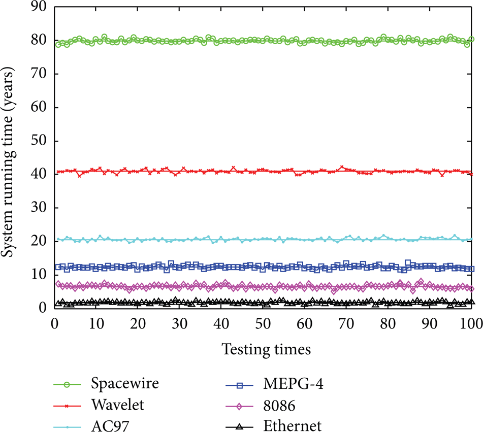
Test results of each application compared with expected results.
As it is shown in Figure 7, each line is the maximum expected system lifetime from (10); the marked points around each expected result are the test results from the 100 times experiments. In Table 3, we present a comparison between the expected lifetime and the average test result of each application.
Comparison of the system lifetime between the expected and test results in optimal partition.

In Figure 7, each application's test results are distributed closely around their expected lifetime. Table 3 only shows little difference between the average test results and expected lifetime.
By using our technique, although some small-size applications (i.e., SpaceWire and Wavelet) have very long lifetime that may exceed the spacecraft's lifetime for current space mission, in the real design, we can use a small-size FPGA for these applications to reduce unnecessary lifetime and save hardware cost.
5.3.2. System Lifetime Comparison between Optimal Partition and Other Partitions
Furthermore, we test other three partitions for each system: tile-based partition (use 1 CLB as function module for fault recovery, a = 1) [16, 18, 19, 31], optional partition (partition application into 3 to 5 modules, n = 3 ~ 5), and nonpartition (i.e., using the whole application as a reconfiguring module, a = A). We compare the experimental results of these partitions with those of the optimal partition. The results are shown in Figure 8.
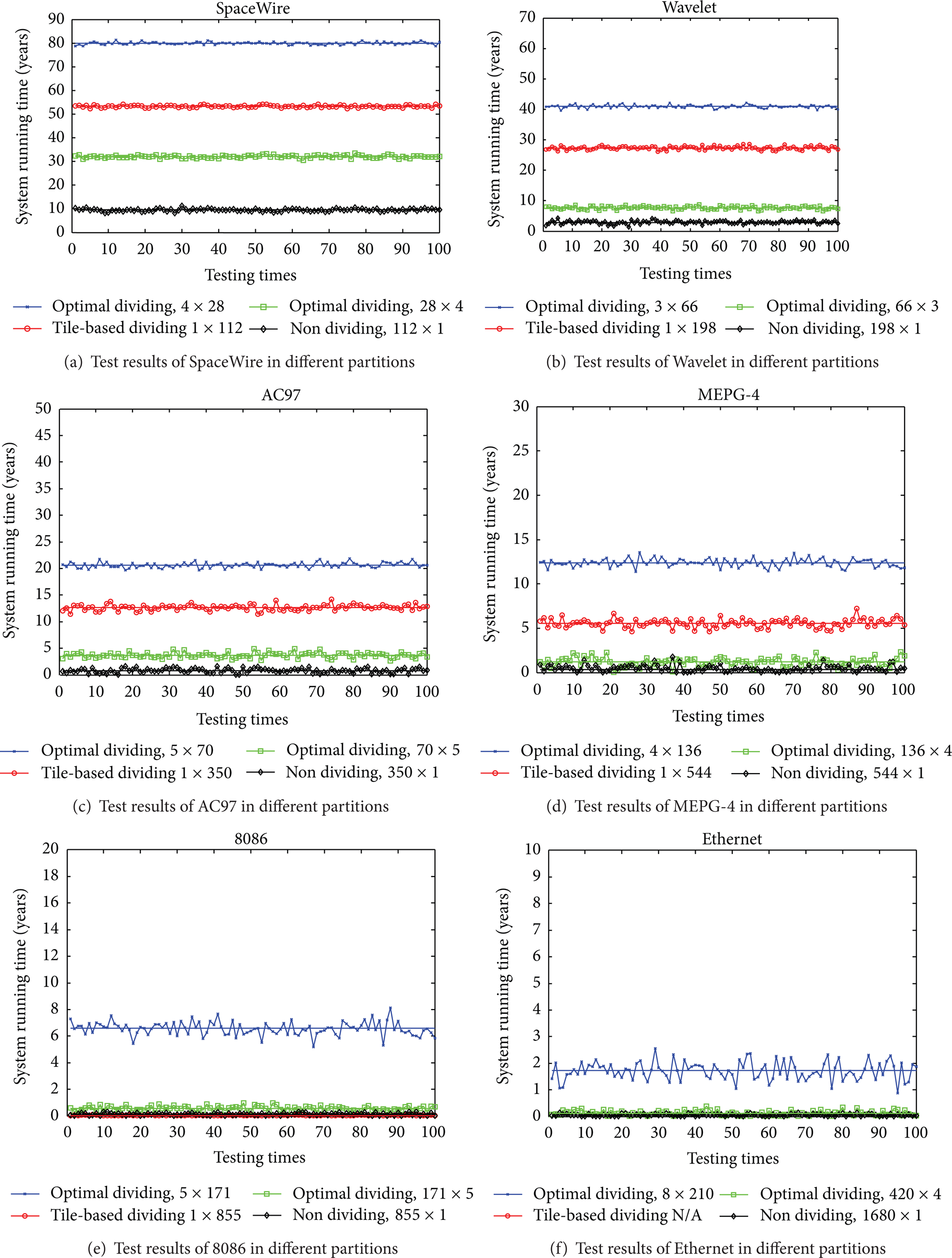
Test results of optimal partition compared to other three partitions for each application.
In every subfigure of Figure 8, every line is the expected lifetime of each different partition from (10); the marked points around each expected result are the test results from the 100 times experiment with different partitions. For each application in Table 4, we present a comparison between the expected lifetime and the average lifetime for each partition.
System lifetime improvements by using optimal partition.

In Figures 8 (d), 8 (e), and 8 (f), because the system lifetimes from the nonoptimal partitions are too close to each other, they overlap each other. For the application Ethernet, with tile-based partition, its space requirement exceeds the whole size of FPGA ((1 + 3) × 1680 = 6720 > 3424), so we did not test this case. Table 3 shows a good consistency between the expected lifetime and the average results even for the nonoptimal partition, which proves the correctness of our system lifetime model.
Compared with other three partitions, our optimal partition always has the better performance in terms of the system lifetime for each application. By using our optimal partition, for each application, the average improvements (with six applications) of the system lifetime over the three partitions are shown in Table 4.
The experimental results show that the optimal partition from our model can have better system lifetime than other partitions in every application. We did not find any routing failure problems during the experiments, and the system performance degradation after each reconfiguration is acceptable.
6. Conclusion
In this paper, we proposed a system lifetime estimation model for SRAM-based FPGAs, which can find the optimal partition to maximize the system lifetime for space mission. We developed a permanent fault recovery mechanism to recover permanent faults by partial reconfiguration. We built a lifetime model to obtain the maximal system lifetime with its corresponding optimal partition. The experiment results show that our technique can effectively improve the system lifetime.